
|
|
Forum Index : Solar : Battery problems and LiFePO4
| Author | Message | ||||
Revlac Guru Joined: 31/12/2016 Location: AustraliaPosts: 961 |
Thank's Mike, I haven't set the pack voltage on the BMS, its default setting is 60v,(not used) will probably change that later and see how it behaves, as its running now its been fine for the 2 systems on the house. They have been set to bulk charge to 56v and float at 54.4v, however the float voltage can introduce some micro cycling between large loads been switched on and off, not really concerned about micro-cycling there has been arguments before and EV's with regen switched on do that anyway. The charge controller's (3 of them) are pcm60X, bought the first one back in late 2015 and the other 2 later, a few months ago one of them decided to run an Experiment for me,   it started reading the battery voltage, 1 volt higher than it really is (It happened before a long time ago and I thought I had repaired it), so bulk charge and float are 1 volt lower on the battery, bulk charge to 55v and float at 53.3v also I'm not using the voltage sense wire on this one as it chose to ignore that last time. it started reading the battery voltage, 1 volt higher than it really is (It happened before a long time ago and I thought I had repaired it), so bulk charge and float are 1 volt lower on the battery, bulk charge to 55v and float at 53.3v also I'm not using the voltage sense wire on this one as it chose to ignore that last time.Anyway as this experiment progressed looking at it on occasions there is very little to bugger all micro-cycling going on, so will leave it this way and see how it compares to the other one after years, its also further from the main battery than the other CC and has a longer battery cable as a result. I don't ground ⏚ the main battery on either of these setups. Battery SOC here is mostly consistent at 70% in the morning the notable change is when we do some shopping and put a few weeks worth of food in the big fridge and freezer and they each work harder all night. Actually that is the SOC reported by the DALY BMS so the measurement will be out a bit. I just stripped the wires back on the Daly Active balance leads so they will fit into the terminal blocks that the BMS wires are connected into, the wires between the terminal black and battery terminals are much heavier, pretty sure the the 17pin connectors are different on these.  Edited 2024-01-13 23:31 by Revlac Cheers Aaron Off The Grid |
||||
| KeepIS Guru Joined: 13/10/2014 Location: AustraliaPosts: 1387 |
I find the variation in voltages between all various equipment really annoying, it's like ever manufacture is using a different reference, and when it comes to LFP batteries you need accuracy, and especially with cell voltages. Interestingly, the DALY BMS current display is very accurate, at least on mine. I proved the HF noise on the DC bus from the Inverter is causing it to jump around though. However the DALY appears to consistently calculate the SOC within 1% or 2% of the JUNCTEK, providing the following does not happen. The DALY SOC gets way off mark if the BMS starts tripping the Charge MOSFET on Cell over voltage, can happen when Active top balancing is in progress, the correct adjustment to Cell-OV settings fixes that, and obviously when the BMS switches the MOS at Pack OV, it sets the BMS SOC to 100%. The connectors for the BMS Cell port and the Active balancer Cell port are a slightly different size, so much inconsistency, and as you noted, even the lead length is completely different and way to short, although I did not have to extend mine, I was able to change the Pack cell layout to accommodate. Oh well, at least it all works in the end so that's a plus  . Edited 2024-01-14 08:15 by KeepIS It's all too hard. Mike. |
||||
| Revlac Guru Joined: 31/12/2016 Location: AustraliaPosts: 961 |
Well I changed my idea just a little,  to do that I would have to shut down the system, disconnect the BMS and go through the procedure again checking wiring etc. to do that I would have to shut down the system, disconnect the BMS and go through the procedure again checking wiring etc.Just reminded myself that if something is working well, leave it alone, so I left it all running and connected the Active balance leads to the battery link bars, could have drilled and screwed onto them but just opted to solder the wires into the exposed copper bars. All the these white plastic batteries in the shed are in a large steel lockable Toolbox, Mounted the active equaliser into the inside of the toolbox plugged it in and it started working, checked the setting on the (old) phone app and it looked the same as the usual BMS, settings all over the place and only the balance light on, sounds about right. Most notable was the cell voltages were very stable and not bouncing allover the place, will connect it to the PC later and see how it works out, its just an experiment. DALY BMS cycle count (if its real) since installed February 2021 , shed battery 121, 1st house battery 271, 2nd house battery 119 all of these 200Ah each. Cheers Aaron Off The Grid |
||||
| KeepIS Guru Joined: 13/10/2014 Location: AustraliaPosts: 1387 |
Yes understandable, that's a much better idea. I soldered mine to the middle edge of the copper link bars in the last 48V LFP I made. I think I mentioned that before, but as it was a new build I also soldered the BMS leads at the same time, put shrink-tube over the middle, done. Really nice way to go with no stupid eyelets or screws needed. In my case, the only thing I look at now when checking the cells in Active balance time is the difference voltage. That is stable as it's a snapshot of the HI/LO cells voltages, it's read when the Active balance logic pauses the balancer to read the cell status prior to selecting the next balance pair. Look forward to seeing if you notice any difference. Not sure on the cycle count, I wonder at what upper and lower SOC point does the BMS logic decide it's a valid cycle and increment the cycle count  It's all too hard. Mike. |
||||
| KeepIS Guru Joined: 13/10/2014 Location: AustraliaPosts: 1387 |
I know I mentioned this before, but just a quick FYI: Using the Phone APP, the SOC and current are not displayed (obviously) but the Equilibrium tab (or whatever it's called) is accessing the settings for the A-Balancer, so EQ current, trip voltage and on/off switch all work when connected to the Balancer port. The latest PC SW V2.1.9 that I mentioned previously has the Active Equilibrium tab. I'm not sure if the earlier version had that setup correctly? . Edited 2024-01-16 13:21 by KeepIS It's all too hard. Mike. |
||||
| KeepIS Guru Joined: 13/10/2014 Location: AustraliaPosts: 1387 |
DALY 200A BMS trap: Found during testing: Mentioned previously: DALY have various BMS Microprocessor platforms, which one you get depends on the options available when ordering, OR make sure it has the ST103 chip set. There is a full Alarm list screen on the PC software, which IMHO is really important when setting up a BMS and finding out what unexpected event triggered the Charge MOS or Discharge MOS to switch off, this list is only available on a BMS with CAN/RS485 option, which is the ST103 Chip Set. New Problem I found: My three 200A BMS units give no indication or alarm if Charge "Over Current" trips the charge MOS. Now the Current sensor in the DALY occasionally dances around because of HF Inverter noise and/or Solar charger noise, even thought the current may be showing somewhat correctly, its ADC output can spike because of noise and cause a false over current trip. There is no intelligence in the Firmware, the Charge MOS is instantly disabled - no Alarm info and no indication of the cause of the MOS switch off. Just one to watch out for, I've had to do a restart of the BMS to get the MOS to switch back on sometimes after this event. If this type of thing happened once in a blue moon you would be pulling your hair out wondering why. Don't know if it's the newer firmware or it other models do this. It's all too hard. Mike. |
||||
| Revlac Guru Joined: 31/12/2016 Location: AustraliaPosts: 961 |
Hi Mike, Given it some time, and the little Equaliser in the shed has made some difference, there is less voltage rise on some of the cells, thing is I have one cell that has been consistently lower than all others at the top end of the bulk charge, its been this way for years and have at times given it a charge up with a 40A charger, the Equaliser should help out with that cell, just don't know how much, time will tell. This one cell would be a real problem for someone expecting to use 80% of the battery capacity every night, but if using 30% or something it's not a problem yet, I could later swap it out for another cell that I have spare, but like to see how far this will go. I think the Cycles are calculated on accumulation of of each percentage of capacity used each day until its 100% then that's 1 cycle? I could be wrong too.  Installed the PC SW V2.1.9 the other night Had to wake it up using the button on the dongle and tried a few settings in the Active Equilibrium tab, some settings were a little different to the APP, also it was set For Li-ion, set it to Lifepo4, it was asleep this morning and it woke up after waiting a few minuets while the battery voltage rises, it had set itself back to Li-ion again, the voltage settings were still as I set them. Found a PC Master Software_V1.0_manual, it sort of explains some things. Oh the old phone app has no way to switch the Equaliser on/off, I think the later version has.  The 150A Daly BMS in the shed has been a rock solid performer even though I have given it a thrashing, the SOC is pretty close too. On the phone app I set the voltage trip a little lower than the BMS and it will give an alarm cell over voltage level 1 and later it will spit out level 2. The BMS will give an alarm "cell over voltage" when the charge mos trips off on the phone APP, I have never had over current so far but have it set for 200A, I think the surge current and time can be set in the pc software, not sure if that really works, they did call it sparkle current on a spec sheet, The first thought when I read sparkle current was the end of the welder, not something that should be attributed to a BMS. So far I haven't used a pre-charge on the inverter charger after the BMS, just slammed the breaker on and give it hell, it must be close to tripping the over current, only done that a couple of times, will add a pre-charge switch one day There is "Current wave" settings will have a look at that soon, might help with more accurate readings. Might have seen this already, or someone else might want it, https://www.microcharge.de/anleitungen/PC_Master_Software_V1.0_manual.pdf Edited 2024-01-18 17:46 by Revlac Cheers Aaron Off The Grid |
||||
| KeepIS Guru Joined: 13/10/2014 Location: AustraliaPosts: 1387 |
Hi Aaron, great to hear: Apology for another long post. As you likely know, lot of talk about when to start Active balance, IMHO there is no one rule for that, it depends on the Cell mix condition, typical charge current and the selected charge voltage for the system. I found that cells in all three 48V packs are fine with a 3.3v start, not the 3.4V or more as some "experts" recommend, in my case due to the lower full SOC and charge voltage. I also need to protect the batteries from over current charge, apart from adding an extra protection layer when running them in parallel, I've had occasions under sudden drop in the night time and early mornings inverter load usage, and with batteries at a lower SOC, the charge current was close to 100A into the 130AH pack, and there is still 20A into the load, and not all of the solar was connected. I now have three banks in parallel, 2 x 170Ah and 1 x 130Ah. I'm just building the fourth bank of 170Ah cells. Once the fourth bank goes in it should never trip my 60A charge setting on the 130A bank. Four banks allow me to use an 80A (or LESS) fuse in each bank, I can draw a 670A surge peak DC input for the big workshop machinery loads and the fuses are fine. At the moment, with only the three banks in parallel, my remaining SOC prior to Solar charges starting is 86% for each 170A pack, and 65% for the 130A pack. In the above result, I'm only charging to 3.346 per cell and then cutting the charge, no tail current at the moment so I might be lucky to be even at 85 to 90% SOC. The Cell voltages quickly drop to 3.34v per Cell unloaded. Hardly any Active balance, if at all. With this usage and the intermittent nature of most of the big daily loads and with four 48V battery banks, my maximum charge current should be limited to around 30A to 40A per battery. The three banks track each perfectly during the charge cycle and SOC calc right up to the charge cutoff voltage. They have recharged from last night and morning usage by 9.45am. All are indicating 93% SOC and sitting at exactly the same Cell voltages. This is confirmed by the JUNCTEK Current shunts and Charge monitors, however the initial SOC set values could have been incorrect. These JUNCTEK are wired between each Blue BMS Bat Neg lead and the Cell pack Negative terminal, the voltage Sense lead is connected to Cell Pack Positive. These are within a few mv accuracy of each other and the three BMS units. Now, I'm fully aware that this is not the correct way to cut charge, however with these settings I'm not going to get much above 85 to 90% SOC, and as my discharge SOC is modest to say the least, these Cells should be quite happy, especially in their AIR conditioned, dry and fully lined room. Just need a top balance every 6 months or so. BTW the Active balancer has completely stopped any cell getting more than 30mv in front as they approach the point of voltage cut off, and this allows the Voltage trip point method to work, for now! I was also looking at the waveforms on DC cables from Inverter to BMS with a 370 MHz BW DSO. A lot of the high frequency noise is from the Solar chargers at higher currents. I already have HF bypass caps and toriod suppression, so I decided to try a 60,000uF CAP bank across the DC cables between the AC Inverter and the Cells and BMS, this made a huge difference to charge cutoff voltage stability and obviously residual low frequency noise. I did not want this high value of capacitance close to the Inverter FETS, there is already 40,000uf directly across them, more than enough to dump a few thousand Amperes and launch the inverter FETS into orbit with an over current fault condition. These new caps are at the end of 1.2 meters of 0G cables coming from the AC Inverter, and mounted very close to the BMS, battery packs and Solar chargers. The only thing is, they also needs an Auto precharge circuit. These are so simple and easy to implement and I would never trust myself with a manual switch, with this value of cap and the low internal R of these units, it's just a matter of when something is destroyed, not if. BTW That is not in response to your setup and precharge as they are different, it's just what 640AH of LFP and 0G cable feeding these caps can, and will do. The current wave setting is just a sensitivity setting for small current (noise) display, so it doesn't hunt around at zero, I think that is also in the Manual somewhere, the fact that they needed this confirms my suspicion of limited HF noise filtering to the ADC current input of the ARM Micro. FYI: The old 12V drop-in LFP battery sets used 100A DALY BMS and I also flogged those, seriously so, and not a single failure, and there were four 12V BMS units connected in "series" between 56V in each of the three parallel 48V banks. You may be right on the cycle calculations, I'm just so busy getting all this redone that I haven't had a chance to even look at it. BTW I'm sick of this humid weather and rain, spent the last few weeks in the Air Con workshop. There is a narrow path that I manage hack out each morning, through what seems like 2m high grass to reach the workshop, it's almost overgrown again by late afternoon, and back to a jungle by morning, rinse and repeat  . Edited 2024-01-19 13:44 by KeepIS It's all too hard. Mike. |
||||
| Revlac Guru Joined: 31/12/2016 Location: AustraliaPosts: 961 |
Will be back later, have to clean up the mess after last nights storm, the local area had no power, generators running everywhere, but hey, I still had power and aircon etc. Cheers Aaron Off The Grid |
||||
| KeepIS Guru Joined: 13/10/2014 Location: AustraliaPosts: 1387 |
Bugger, hope you don't have much damage. Bet it was nice having the backup and aircon with these humid nights  It's all too hard. Mike. |
||||
| Revlac Guru Joined: 31/12/2016 Location: AustraliaPosts: 961 |
Cleaned up some of the trees that smashed the front fence there would be a truckload or more of other trees that I won't bother shifting, I haven't even looked down the back, Doesn't matter. The rain come in horizontal and got everything wet under the verandah and 6 feet up the wall, in the end of the shed everything got wet, but the solar gear was ok, the batteries BMS and The equaliser were all bolted into the Big steel tool box, its all dry inside and working well, the toolbox turned out to be a good idea. Yep totally agree Do you have any current limit settings on the charge controllers? It might not matter after your setup is finished. I have mine limited to 50A per battery bank, there is more solar power available and that works when its not so sunny, the CC will do 60A but I should change the 32A input fuse, pulled the Anderson plugs last night incase lightening hit the solar array. The equaliser Didn't wake up till late today, but it didn't run for long that I'm aware of busy with everything else. This might be different, the voltronic inverter is making the BMS read current incorrectly, the charge controller is ok with the inverter switched off and the BMS reads quite stable, been a while since I tried that. Between the 2 of these there is not much capacitance compared to the home built inverter that will soon be installed, will need the pre charge resistor in place then. Just realised the large capacitor in the Telecom battery charger is 9000UF 75v with a ceramic resistor across it, I have just switched on the DC breaker and never thought about the BMS handling that, one day I might not be so lucky. I wonder if there is another way to do this, filter the noise etc. We are in for a few more humid days yet, 2 aircons going today, I was cutting tall grass the other day, working in that stuff is nasty in these conditions. Cheers Aaron Off The Grid |
||||
| KeepIS Guru Joined: 13/10/2014 Location: AustraliaPosts: 1387 |
That's a real pain, must have been some serious wind there, thankfully you took the right steps to protect the Solar. I've gone as far as I can removing HF noise, there is only so much you can do. That 60,000uf bank I'm testing is obviously not going to have any effect on HF (RF) noise. I just needed to dampen some very small low frequency ripple/noise pulses on the DC line. The line disturbance is caused, in part, by the way I'm disconnecting Solar charge to each battery bank, along with Inverter-Fridge Freezers, Inverter-AirCon and pulse ramping loads. These can run for extended periods of time, as in hours. This mix of small ripple harmonics and pulses are exasperated by the way I'm testing the LFP charging cycle control. If I were doing it correctly based on low charging current cutoff point of a % of C for X charge voltage, there would not be the sudden voltage steps caused by Solar charge disconnect to the batteries under a higher charge current cutoff. The sudden pulses upset the crude setup I'm testing with. The Cap bank has almost eliminated that entirely. It doesn't really cause any issues, but I know it's there and it annoys me. Unfortunately the only way to reduce power (current) output in these solar regulators is to reduce solar input. As you know, typically you match the MAX solar array input Power to a margin below the solar regulator peak rating, allowing for worst case OC voltage /power limits. These units are simply 60A max rated output, obviously allowing them to produce more will likely cause a sparkle. BTW I don't connect the solar charges directly to the batteries any more, the solar is connected straight to the Junction of the Inverter DC cables and the switched battery bank output cables, this junction is where the 60,000uF bank sits. One solar charger can be switched across to any isolated battery bank for isolated charging if needed. You are correct, the 4th bank will mostly eliminate the problem for now, so will setting it up correctly once the testing and rewire is finished. Hope you don't get another storm, last thing you need, see Monday might be even hotter then today. It's all too hard. Mike. |
||||
| Revlac Guru Joined: 31/12/2016 Location: AustraliaPosts: 961 |
I also have the charge controller's connected close to the inverter, about 1m away (cable length) the one in the shed is about .5m and connect to the bus bar. Last night mucking around I found a clamp on ferite ring on the output of the charge controller, don't know when I put it there, anyway clamped it onto the negative cable between the inverter and the copper bus bar and noticed the ferite ring vibrate in my hand, let it slump on the cable and could hear it ringing, sounds like 50Hz, so removed it, all this is going through the BMS (I refer to it as a Battery Management Switch) the ferite ring made no noticeable change in the current reading on the phone app, sort of expected that. Anyway everything is working well and will see how or if it changes when I put the Homebrew inverter in place, I have run the previous 2 builds on FLA batteries but not on the lifepo4 battery yet. Looking forward to a bit better weather. Cheers Aaron Off The Grid |
||||
| KeepIS Guru Joined: 13/10/2014 Location: AustraliaPosts: 1387 |
The fourth 48V battery is up and running, I now have a total of 655ah. The last three of the old 12v batteries also had genuine EVE cells, I scanned them and it came back with date of manufacture 2020, almost four years old now. So the bank has twelve 4 year old EVE cells, and four new fake EVE cells from the 12v battery that I was gives as a warranty replacement. I charged the four new cells up to the same resting state as the twelve EVE cells. I used an adjustable 0-5v @ 30A top balancer supply to do that, but I did not top balance the pack at this stage. Connected to solar, I was able to limit charge current to 50A and the bank charged up without tripping the balancer. Either the old cells are still good or new cells are a bit aged, but dam they tracked well considering age difference and cell quality, I have not top balanced them, but obviously my lower charge level makes a big difference as it's set just below the steep knee in the charge profile, which will obviously really amplifies any cell variation. BTW: My new 5 1/2 digit 0.0015% accuracy bench DVM arrived. I am sick and tired of trying to figure out which meter is correct. I do have a fairly accurate 0.1% 3.3v reference, but I soon realized that the typical meter is not linear enough across the range from 3v to 60V for it to be of much use. Every meter I had is inaccurate, some by 40mv and another at 120mv, and obviously ebay/ali low cost panel meters (random number generators) were all over the shop. This is very frustrating when measuring 3.2v LFP cells, where 100mv can be over 30% resting SOC difference in LFP. Now I can adjusting them and also monitor the drift. The JUNTECK were only 10mv out at 53v, so 53.24v read as 53.25v on three units, the fourth unit read low at 53.23V, I was able to bring the three high reading units down 10mv, good enough for monitoring the four 53V battery packs. It's all too hard. Mike. |
||||
| Revlac Guru Joined: 31/12/2016 Location: AustraliaPosts: 961 |
Hi Mike, That all sounds good, enough power to keep every happy for a while, I agree about the multi meters, all the ones here are different, just remember to use the same one when comparing certain things so at least the readings mean something. The local shop has 100ah cells at half price at the moment, Hopefully they do that with the bigger cells at some stage. Cheers Aaron Off The Grid |
||||
| KeepIS Guru Joined: 13/10/2014 Location: AustraliaPosts: 1387 |
I noticed that, seem to be selling a lot of 230ah to 280ah lately, it could be a reason for the reduction of the 100ah cells, The 130ah EVE cells I purchased a while back were reduced considerably. Actually I'm in the process of calibrating the other meters to match the new unit, although they will drift, especially being hand held units, but at least they will be close enough for most work, and I now have something to calibrate against when needed. Measuring cell voltages will be left to the accurate bench unit. I took a few pictures of the final work in progress tidy up. The cabling to the four battery isolation switches and Fuse blocks is 0G and the Copper Bar is 38mm X 4mm, the switches bolt directly to the copper bar, this allowed a simple compact high current setup with the shortest cable length possible. The 50mm AC Inverter input cable and 50mm 150A Solar charger cable bolt directly to the copper bar. There is a big cap bank also across that point that still has to be mounted correctly. 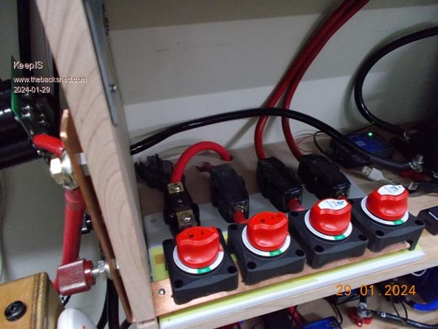 Below: Four independent battery bank monitors and the DALY touch LCD display. The LCD will have a 4 position switch next to it, it will switch data/control between the four BMS UART ports. 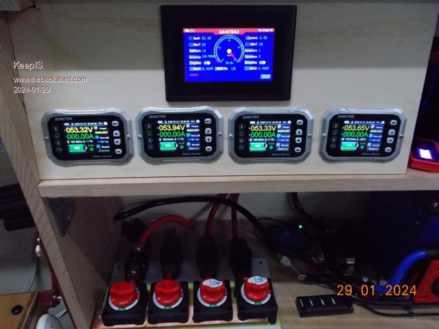 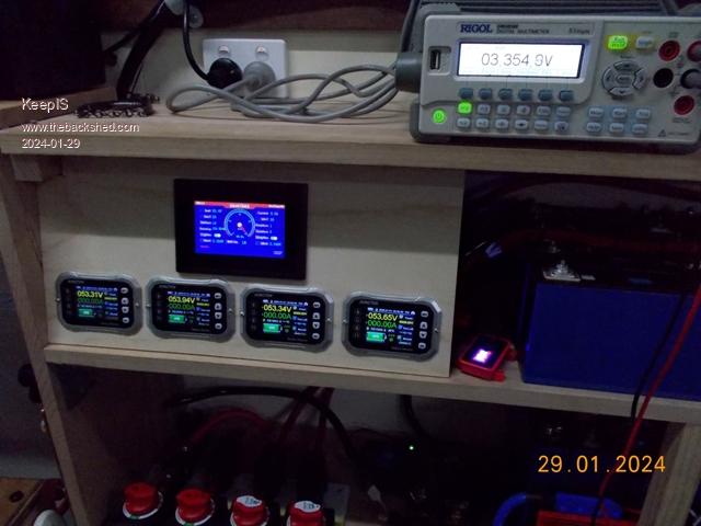 . It's all too hard. Mike. |
||||
| Revlac Guru Joined: 31/12/2016 Location: AustraliaPosts: 961 |
That's looking very neat and tidy, those big isolation switches should work well, I had other sorts that give a lot of trouble with internal contacts degrading over time without use ( sometimes I learn from my mistakes), so will change over to decent switches.I'm thinking about running the 2 200Ah battery bank's in parallel so it will be a 400ah house battery, likely join them on the outside of the battery box, still have much to do before then, gather parts etc. Cheers Aaron Off The Grid |
||||
| KeepIS Guru Joined: 13/10/2014 Location: AustraliaPosts: 1387 |
I've been using them for 4 years now, used on a 24v system before this, even accidentally switched the DC line to the 24V inverters when the caps were discharged and almost jammed them a few times, but still running fine. It's all too hard. Mike. |
||||
| KeepIS Guru Joined: 13/10/2014 Location: AustraliaPosts: 1387 |
Thoughts on the larger DALY-BMS LCD Touch screen display: The LCD is shown sitting above four JUNCTEK battery monitor screens in the last picture posted. The screen comes in two flavors of COM port, UART or RS485. Not all DALY BMS will have a CAN/RS485 port, I have the UART unit as one of my four BMS does not have RS485. The Screen comes with a short cable with a 6 pin plug on each end. The BMS UART port and LCD screen port use the same 6 pin connectors. I purchased eight 6-pin plug and socket sets, these come with fly-leads attached and they 100% match the DALY UART ports, found some on line for low cost. So glad I also got the sockets. The LCD monitor itself only needs 4 connections to work, +12v, RX data, TX data and Ground. You could use an external +12v supply, but 12v would need to be interrupted as you switch between each BMS, the DC supply interruption is needed to force a re-read of data from the BMS and to start coms with each selected BMS. There is a pin on the BMS UART port that supplies +12v, there is an optional 5th wire if you wanted to utilize the BMS Activate / Deactivate function using a momentary push button switch, IMHO you really want this. The 6th wire in the UART socket is +3.3v and not needed for the LCD screen. I have four BMS units that I wanted to monitor these without using a phone, Bluetooth or PC. I initially thought this LCD was a bit of a gimmick device, but I really like the unit now. It does most of functions of the PC software, but does not handle the active balancer settings, and you cannot set the cell high or sum high voltages, you still need the PC SW to do that. I used a separate 12v plug pack to power the LCD, this is powered by a UPS which also powers the Network routers, VIOP, StarLink and the main Solar logging micro controller and main PC. My solution worked out really well as it allows just one UART connection to have access to any BMS device and its active balancer or display them on the DALY LCD. Note: The LCD will also display the cell voltages read by the Active balancer, but it cannot change the current or voltage trip values in the balancer. I happen to have a 5 pole 8 position switch, hard to get these days, but there are small IC to do this now. The 5 poles are for 1: RX-D, 2: TX-D, 3: Activate button, 4: Ground and 5: 12V from the plug pack. The +12v is interrupted as the switch rotates, the switch wafers are break before make, this causes the LCD to request a data update from the selected BMS. The 8 positions allows me to select any BMS or Active balancer to display on the DALY LCD monitor, or switch to the PC software via the USB connection. The COMS switch is a 3 pole 2 position switch (Jaycar) it changes the selected COMS RX-D, TX-D and GND lines between the UART PC cable and the DALY LCD screen. A DALY PC to USB adapter that comes with the each BMS, plugs into the switch via one of the socket sets I purchased, the LCD display and the COMS to each BMS and Active Balancer also use these plug sets. The BMS UART output is TTL (3.3v) level, so switching between each BMS does not affect the PC serial connection or Software when it's running, switching back and forth between the LCD screen and PC connection / software is also seamless. It means I can start the PC Software and leave it running on a small tablet or laptop, then switch between any BMS without the need to touch the Laptop / tablet or LCD to show the results. To overcome any ground issues, it's important to switch the ground connections with multiple BMS, that's why one bank of the switch is for ground switching between devices. The charge and discharge FETS in the negative battery connection conduct through the FET body diodes in the OFF state. Joining thin ground wires together could cause problems if that bypasses the body diodes of a BMS that has a disable MOS switch. The DALY LCD is easy to read, allows quite a few settings to be simply changed and has 3 screens of data, including the typical page of individual voltage for - in my case - 16 LFP cells. Touch response is good. The only negative is that it needs to be angled correctly to get good contrast, I was able to do this easily, in use this has not been a problem at all. Since acquiring an accurate DVM, I have found the DALY BMS voltages to be very accurate and within a few mv of the displayed voltage, the current display is also accurate, except for it's poor immunity to Inverter noise, but the JUNCTEK battery bank monitors handle that perfectly. . It's all too hard. Mike. |
||||
| KeepIS Guru Joined: 13/10/2014 Location: AustraliaPosts: 1387 |
For anyone interested in the correct 6 pin connectors for the DALY BMS UART port. adafruit.com Core Electronics AU . It's all too hard. Mike. |
||||
