
|
|
Forum Index : Electronics : Builiding of a complete 6kW PV inverter with MPPT chargers
| Author | Message | ||||
| KeepIS Guru Joined: 13/10/2014 Location: AustraliaPosts: 1872 |
Very nice, from what I have observed on my panels and chargers, 0.5 sec should cover it. NANO Inverter: Full download - Only Hex Ver 8.1Ks |
||||
| -dex- Senior Member Joined: 11/01/2024 Location: PolandPosts: 101 |
Small update about OVP mppt circuit. As I said earlier, I have a relay on the board that turns on/off the BAT-12V converter that powers all MPPTs. The converter has low ESR capacitors at the input, which stuck the relay together during one of the subsequent tests. So I'm making a small soft start circuit: a serial NTC thermistor, or a resistor + relay powered from the output. Moreover, in this casing I placed a caps mppt pre-charging system - behind the kilovac relay, activated manually with a switch.  |
||||
| -dex- Senior Member Joined: 11/01/2024 Location: PolandPosts: 101 |
Next update to the above circuit. I made a soft start of the DC converter, it is a 100R resistor in series, shorted by a relay powered from the output of the converter. The problem with surge current and welded relay contacts, has been solved. Hopefully? This is way you should not do this way with this converter. Since using this system, another problem appeared: after several successful starts, the next one caused one of the tlp250 and its isolation dc-dc converter (mppt pwr pcb) to burn out. They have been fixed. And again, a dozen or so correct starts, and the next time the capacitor (10uF 16V tant) at the oneof brainboards stabilizer was damaged. The explosions occurred exactly when the 12V converter was turned on. Why? So I went back to this large common 12V converter and analyzed again what was wrong. It looks like it's feedback system doesn't work fast. First, my start-up circuit charges the caps through a resistor to a certain voltage that allows it to start, and then suddenly increases the voltage at the input by closing the charging resistor. There must be a short voltage spike at the output - some elements take over, others burn out. Therefore, starting the converter must be done differently. I changed the values of some caps, and added a surge diode at the output. The converter had an original on/off switch which has now been replaced with relay contacts (SPDT). From now on, the MPPT ovp protection can safely turn on and off 12V PS for all MPPT chargers and the kilovac relay. Yes, I confirm, tantalum caps do not like momentary voltage rises. 7805 IC survived. 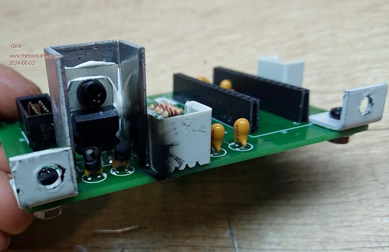 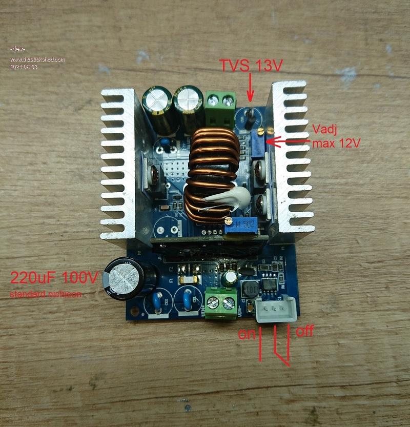 |
||||
| -dex- Senior Member Joined: 11/01/2024 Location: PolandPosts: 101 |
Amnesia issue I have the impression that I'm having problems that nobody haven't seen before here, so I'll describe another one  I do this in the hope that if someone encounters it, they will have a solution ready. I do this in the hope that if someone encounters it, they will have a solution ready.This applies to the inverter and the lcd display, or more precisely, both nano controllers. It happened several times that the nano supporting lcd display losed their own code. It looks like this: the inverter and display everything works perfectly, I turn it off. Reboot: the inverter's starting is correct (I can see it on the diodes), but the display now has random characters or there is nothing here, and from now on you can't do anything with it. Well, maybe. I re-upload the serial lcd nano code and it still works properly. It will run several or a dozen times and again when I try to turn inverter on I don't see anything. So I program it again, and the LCD continues to work as if nothing happened. Everything happens randomly, but we are still talking about a situation where I turn off the inverter and wait until the caps are fully discharged. The above problem also affects the nano on inverter controller board, although the frequency of the problem is lower. The diagram is identical: the inverter works, then I turn it off. Reboot and I see that the inverter does not start, no reaction, and I have a welcome message on the LCD: Serial -> LCD, pin D4 for RX etc. which means that the LCD does not receive data. So I take this nano, re-upload the code and everything goes back to normal. Back to normal? No, because after some time the problem repeats itself again. I called this problem memory loss, or simply amnesia. I noticed one more thing that has always been there: while the inverter remains turned off, the caps are discharged, and at the end of this stage, the 5V voltage starts to pulsate, probably something like in the attached picture. I then see the diodes on the nano board flickering and flickering less and until the voltage drops completely. When nano's diodes flicering, lcd flicering too, due they have same 5V voltage supply line. 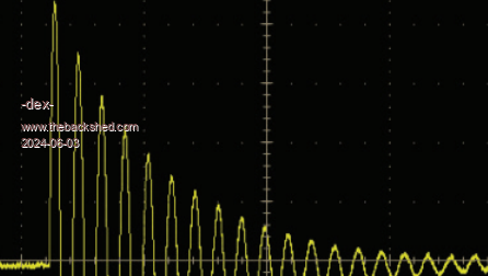 Reasuming, if I was able to reload the code, it means the bootloader was not corrupted, atmegas has some special place in flash memory for bootloader. Also the settings and calibration data were saved in the eeprom memory, not changed or deleted durring amnesia occurs. I talked to KeepIs and here is what he suggested me The only thing I can thing off is the that the Boot Loader in the Nano is seeing a control character on power up, and it thinks it's the command to load new firmware, and it's loading the LCD data stream over the LCD code and making the Nano appear to loose the program. So if the above is true, you should change the bootloader, or delete it. I decided to remove the bootloader - I deleted it. I uploaded the inverter code to the nano using the USBASP programmer and the ISP interface. KeepIs wrote more about this in his thread. The nano inverter and nano LCD have been working without a bootloader for over two weeks, during which time I have performed many start-ups and the problem has not occurred. The problem of amnesia has been forgotten  Edited 2024-06-03 20:51 by -dex- |
||||
Revlac Guru Joined: 31/12/2016 Location: AustraliaPosts: 1153 |
Yes had it happen a few times, power to the nano must be either on or off, a power supply running the nano switched on and of repeatedly when the caps were almost drained. This happened on the old MAD inverter a few times, I had to program the nano again and it was difficult to get the program uploaded, had to wait a Little the press the reset button and after several attempts the upload worked. I have since put a switch on the PSU so the power can be turned off and let the caps drain slowly without any effect to the nano. Willing to try this at a later stage.  My copy and paste is a bit much. Edited 2024-06-03 21:20 by Revlac Cheers Aaron Off The Grid |
||||
| wiseguy Guru Joined: 21/06/2018 Location: AustraliaPosts: 1206 |
Thanks for that info Dex. I did not get back to you about the problem as I was snowed under getting this project over the line finally. I also was not sure of exactly what was transpiring except you said the code needed reloading. The information you have posted above does help a lot in explaining the issue. After the inverter is turned off and the solenoid opens, charge can re-accumulate on the main capacitors, when the main capacitor voltage gets to ~ 7VDC the 5V line starts and the Inverter and LCD micros start poorly as they come to life and the LCD & LEDs light the power drain makes it shut down again and the cycle continues a few times. I do believe that this is what causes the software to go off the rails. the fix I think is going to be relatively simple. We need to ensure that when the inverter is turned off and the solenoid turns off at the end of SPWM ramp down we need to drain any energy accumulating in the main capacitors. For instance if an 8K2 - 10K resistor is placed across the inverter off wire to ground when the inverter is turned to off then I suspect enough energy will be drained to stop the false restarts. I will look further into this - I have not evidenced it here but you are probably using a lot more capacitance on your inverter than I am (what is your capacitor value in total?) Whilst you (KeepIS...) has found a valid way to stop software corruption I assume the flickering lights still continue after shutdown? If the answer is no that worries me a little because something else is going on as well. If the flickering lights continue just scaling the two resistors on the main PCB from (R27 & R28) 27K & 4K7 and using instead 6K8 and 1K2 at least 0.5W resistors (they only consume power for a few seconds until shutdown occurs) the problem should be gone. Given that you have a working system maybe - if you are prepared to help a little - you could temporarily connect a 8K2 from shutdown to ground and see if the flickering lights stop (this is an easier way to test if the 2 onboard resistor changes will stop the issue). If the flickering lights stop I am confident the code corruption will be sorted too. I am not asking you to change Nano code just confirm the blinking LCD is not flickering any more, if not more drastic action is needed - this is just a rather simple solution if it works. Edited 2024-06-03 22:31 by wiseguy If at first you dont succeed, I suggest you avoid sky diving.... Cheers Mike |
||||
| -dex- Senior Member Joined: 11/01/2024 Location: PolandPosts: 101 |
Removing the bootloader did not cause the LEDs to stop flickering when turned off. In the KeepIS inverter, this flickering also occurs when the inverter is turned off, but it does not cause amnesia. Perhaps the same BOM has minimal bit deviations. I used PS1 and PS2 according to the BOM, purchased from digieky. C24 C25 C26 - here I wanted to do better than require and I used top quality caps, low esr. Perhaps our nano clones and their quality are different. Earlier, I added an additional tantalum capacitor at the end of the power line, right next to the nano LCD, and this made the amnesia problem much less frequent. Caps on the power board are 8 x 4700uF. I will check later what values of the R27/R28 divider could discharge it smothly. |
||||
| KeepIS Guru Joined: 13/10/2014 Location: AustraliaPosts: 1872 |
I applaud Dex for the things he has been trying to solve his problem, It's interesting to hear that Aaron has seen this on his Mad inverter. I went into great depth to try and duplicate the condition: So here a few things to add into the mix. I have been spending 5 to 6 hours a day for the past month or so testing for every possible failure mode for the Nano controller - there is no failure mode for the WG Power board or Controller Hardware, baring poor quality component failure! So the focus has been on the small Nano PCB and firmware - with respect to the very RF noisy environment that it is operating under. I have not had a single instance of noise induced failure or a single glitch. My testing has been on two different inverters: 1: My recent backup Inverter build on the Test bench - with wires everywhere. 2: My totally abused Big 3 stack toriod Main Inverter - both are running Nano controllers. I have tried ever possible supply variation and have not been able to cause a corruption of the Controller Nano. However early on I did see a corruption of the LCD screen, but a simple reset or power cycle fixed it. I have been using the same "LCD with Nano" for both inverters. I have removed the LCD from the running inverter and reconnected countless times, even plugging it in back to front twice on the backup Test inverter  I have never had to reprogram the LCD. The LEDs on the Nano PCB in the controller have always flickered on and off as the power supplies fade down to zero - The Brown out setting in the Nano kicks in at a very low voltage, however that is way below the Power board cutoff - so the inverter has powered off before that event. This is expected behavior with switching supplies. Dex mentioned the power supplies, that was a thought, as I have a different 5v regulator. I spent a good hour trying to corrupt the Nano board on a test power supply with DSO monitoring - I could not - so partly ruled that out. These inverters have been powering off with a good 3 to 4 seconds of flickering LEDS over 20 times a day for over a month - No LCD or Nano problem. I have a 1m long lead running from the controller board to the LCD, some times sitting the LCD next to the 3 stack toroid and chokes during testing - not a problem. FYI: I have tested cap bank values from nothing to 40,000uf. I think wiseguy partly welded his Kilovac contacts together when closing the Kilovac with out pre-charging the Cap Bank. I did that with 40,000uf capacitance - virtually NO cable loss, and 4 banks of LFE in parallel at nearly 40Kw, - I can confirm doing that will partly weld the contacts on the latest Kilovac. I had to take it out and beat it to death to release the contact - it still works - but swapped it over as it's in the big inverter - the abused Kilovac is now my test unit. So, Dex definitely has an issue, something strange is going on, and it's across different plug in Nano PCBs and also on the Solar regulators. One difference I can see is this: The build of the "LCD PCB with Nano", mine is home made, no caps, just the LCD and Nano on vero board and 1m of 3 separate wires twisted together - no screen. I really doubt the power supply and flickering LEDS are the problem, the Nano on the controller never fails, and they both run from the same 5v supply. One way to quickly check: Power the LCD from a small 5V plug pack, that eliminates the supply to the LCD - see if it fails. . Edited 2024-06-04 09:22 by KeepIS NANO Inverter: Full download - Only Hex Ver 8.1Ks |
||||
| nickskethisniks Guru Joined: 17/10/2017 Location: BelgiumPosts: 462 |
A few years ago I had this similar problem caused by 2 dcdc converters after each other, 48-->12V and 12-->5V. When going from 12-->5V with a lm7805 the problem was solved. (Could have used the onboard regulator, but I didn't) I had the impression a small negative pulse was the cause, but I never tried to invoke the problem again. |
||||
| wiseguy Guru Joined: 21/06/2018 Location: AustraliaPosts: 1206 |
Mike I have found in my lifetime that you should never say never. Before you relegate my theory to the waste bin I have a few comments to make. Are you using exactly the same Nanos as Dex is using from the same supplier ? What is the relativity between the two Nanos timings of coming briefly to life with maybe multiple flickers of data lines (when brownout detectors are at their thresholds? This in my opinion is a bit of a can of worms and supply voltage reset ICs were designed to solve these types of issues. But brownout detectors on 2 devices (think LCD nano and inverter nano) may not be perfectly matched so they might not "die" at precisely the same time, leaving one to maybe see crap data from the other. I am more than happy to be wrong about what is causing this but I find faults by eliminating the low hanging fruit first. I have ripped up and remade what was a perfectly good PCB design by not understanding exactly what was causing the issue only to have it still present on the new design. One of the first mantras in microcontroller design is ensure the power supplies are valid. The very fact that it is a random occurrence and not able to be reproduced easily has all the hall marks of being caused by the random flickering being seen on the LEDs I believe Dex also said that he lost the code in The inverter Nano at least once. Remember that brownout detectors are not 100% infallible they can give a solid (perfect) output when the supply is falling, it is at the other end when they are coming to life from a low voltage and their detect circuitry may be a bit unpredictable could that maybe be allowing the data corruption ? I am using cheap Nanos and I have never had a case of amnesia (corrupt code) with LCD, Variac or Inverter codes. I would hate to guess how many hundreds of times I have powered up/down and glitched power as well. But 95% of my bench testing is with power supplies that turn off and stay off and I also dont use massive cap banks, but this will change in the near future. Edited 2024-06-04 10:45 by wiseguy If at first you dont succeed, I suggest you avoid sky diving.... Cheers Mike |
||||
| KeepIS Guru Joined: 13/10/2014 Location: AustraliaPosts: 1872 |
I think I said "partly ruled that out and Doubt"  but I agree, it's still in the back of my aging mind. but I agree, it's still in the back of my aging mind.  The BOR tries to reset the Micro below a reliable voltage point, but the catch is the Nano on the controller has more then one potential source of power via the ESD protection circuitry. It has all the powered I/O pins to keep it ,briefly false powered, and possibly bypass BOR detection. The LCD has one buffered Data line and a common 5V rail. So yes, there is a difference. I have a mixture of Arduino Nano boards, from the cheep clones, mid range clones, and expensive real Nano. I swap them in and out all the time - and all work perfectly. When you consider that the LCD only has one possible ESD path via the Data line, it is strange that it's the problem child. The only Nano corruption issues I can find in a search are during bootloader code upload interruption, which is a given! I might have miss-read the post from Dex, but since Dex has removed the bootloader from the LCD nano, it appears that his problem was solved, however the bootloader cmd sequence is not controlled by the Nano-LCD data pin, and noting is being loaded. If the Nano-LCD without bootloader continues to work correctly, then it's possible that the failing +5V line and BOR resets (search for bootloader cmd) are intermittently causing the LCD-Nano to think it's in bootloader mode for a fraction of a second, and corrupting the code? If so, that an easy fix. If I'm wrong, I'm sure Dex will let me know, and if the LED without bootloader is working, and continues to work, hopefully Dex will let us know. . NANO Inverter: Full download - Only Hex Ver 8.1Ks |
||||
| wiseguy Guru Joined: 21/06/2018 Location: AustraliaPosts: 1206 |
I forgot to emphasise what I consider an elephant in the room, I believe Dex said everything is working fine and he shuts it down but next time he turns it on code might be damaged. But I think it more likely than not that its not the power up but the flickering LEDs symptom that occurs after turn off is when the damage is being done. Coincidence?.... maybe not. Yes you did say doubt, but I only rule out something doubtful after it has been proved to be blameless (and even then, is there a 1% chance??) until then everything is under suspicion. If at first you dont succeed, I suggest you avoid sky diving.... Cheers Mike |
||||
| KeepIS Guru Joined: 13/10/2014 Location: AustraliaPosts: 1872 |
The flickering LEDs we see are the TX and RX LEDS. The LED on D13 does not flicker. These are driven by the USB FT232RL or equivalent, we may be seeing the USB chip going nuts because of low voltage - maybe it's not the Nano? - I have not looked at the Tech info for the USB chip. The PWR LED gives a single flick, "on mine", right as the Nano stops. This agrees with some test Code I wrote to see if the Nano tries to restart on power down. I always got 1 restart. Now here is the interesting thing - The RX TX flashing means that the USB controller is sending crap - it's possible that the scenario I mentioned may be valid, and indeed, the USB controller (or Nano?) is randomly corrupting the LCD boot loader, but why only on the LCD Nano?. The Controller Nano itself appears to be powering down correctly. I will need to get a DSO onto the Controller to 100% confirm this, but I can't do that today. NANO Inverter: Full download - Only Hex Ver 8.1Ks |
||||
| morgs67 Regular Member Joined: 10/07/2019 Location: AustraliaPosts: 78 |
A voltage supervisor reset IC may help. These hold the micro in reset before falling supply voltage allows the micro to operate at a voltage that causes unstable/unsafe operation. Tony |
||||
| KeepIS Guru Joined: 13/10/2014 Location: AustraliaPosts: 1872 |
Yes, but there is no unsafe operation voltage for this WG Inverter design under any voltage conditions. Just as an FYI: Wiseguy can correct me if my memory is hazy In Test Mode: AC output is continuously variable, by virtue of Input voltage being continuously variable from 0V to 60V. At around 13V to 16V, the INV Power board isolated supplies will turn off. That voltage is above the 12v input regulator and following Nano 5v regulator, the 12V regulator will run down to below 10V in mine. Nano is still 100% stable with 5V at that point. In my Nano code, I halt the Nano executing below a set voltage. This is WAY above the BOR point and above +5V. Finally, there is no need to worry about Nano low voltage running as the inverter powers down, SPWM drive is ramped down and halted at 51V in my inverter (in Normal INV mode), add that to the above and it's not an issue. . Edited 2024-06-04 15:42 by KeepIS NANO Inverter: Full download - Only Hex Ver 8.1Ks |
||||
| wiseguy Guru Joined: 21/06/2018 Location: AustraliaPosts: 1206 |
In test mode the inverter ignores the Vcap or Vin low threshold levels and as long as there is 5V on the Nano it will output SPWM. If the input voltage is below the start voltage of the 12V switching regulator it obviously will not function. You want to have a good 12V stable supply if you want to vary the input voltage in this mode or the Gate drive power supplies may not drive the FETs on fully. So if you want to run in test mode AND create AC power, then run the input voltage from at least 16V upwards to whatever you call max ie 55V and the output will rise until the mains output is at the level where the feedback operates and then no further increase of the input voltage will show at the output - it remains at the regulation point. If you supply the Controller card with say 16V so the 12 & 5 are established properly and then supply a separate DC supply to the power FET board then you can vary the AC output from 0V input upwards for the power stage supply, but when you get to the regulation voltage point the output voltage again should stop rising despite further increase to the power stage voltage. Note the SPWM will be at 99% from zero until it starts regulating and then the % will then come down proportionately. Edited 2024-06-04 16:31 by wiseguy If at first you dont succeed, I suggest you avoid sky diving.... Cheers Mike |
||||
| -dex- Senior Member Joined: 11/01/2024 Location: PolandPosts: 101 |
The amnesia problem affected both nanos: the nano-inverter and the nano-LCD. After these events, I replaced the nano with new ones, they were also affected by amnesia. All nanos used in this project (also mppt) have a 328PB onboard chip and standard ch340. Nano-LCD was definitely more common, perhaps because the connecting cable is about 1.5 m long. I found a video that shows nano-lcd amnesia. You can also see there that the inverter is started correctly. The second video is a nano-lcd "repair": re-uploading the code. Video 1 Video 2 Both of them still had a bootloader at that time. I failed to record the nano-inverter amnesia. But I assure you it also occurred. It has never happened that both nanos experienced amnesia at the same time. I will try to record the controller to show what the diodes on the controller board and the nano do when powering off. Edited 2024-06-04 19:16 by -dex- |
||||
| KeepIS Guru Joined: 13/10/2014 Location: AustraliaPosts: 1872 |
Mike and Dex, my inverter is not flashing any LED's, I tried everything. The Green LED on the controller board mimics the PWR LED on the Nano, as it should. What is your Green +5v LED doing on power down? The only thing that has changed: - it's late and the solar chargers are not running, they put a lot of noise into the Power rails. Are we chasing a noise issue on the supply right at the point of the +5V rail drop out. I have programmed four different Nano boards, and nothing I do will get any flashing - there is none on the LCD either. The Nano is behaving exactly as it does on the Bench on a very slow decaying SMPS. Just the slightest flicker of the Nano PWR LED as it's almost out - nothing else!   I'm calling it a night I'm calling it a night . NANO Inverter: Full download - Only Hex Ver 8.1Ks |
||||
| KeepIS Guru Joined: 13/10/2014 Location: AustraliaPosts: 1872 |
Just saw the Videos, the first one with blocks looks just like the LCD did not initialize, but you said that you had to reprogram it before it would work again? I assume that since you removed the bootloader it's now running fine? Note my post above - No solar and No flashing - I will have to wait until tomorrow when the system charges to confirm that observation. DEX can you make sure to load the latest code I sent before testing! . Edited 2024-06-04 19:42 by KeepIS NANO Inverter: Full download - Only Hex Ver 8.1Ks |
||||
| -dex- Senior Member Joined: 11/01/2024 Location: PolandPosts: 101 |
To make lcd work again, it must be reprogrammed, as shown in the second video. If it is not reprogrammed, restarting inverter and lcd doesn't not help. It was previously programmed using the bootloader. The whole situation repeated itself several times. After that the nano-inverter and nano-lcd have been programmed without a bootloader and amnesia does not occur. |
||||
| The Back Shed's forum code is written, and hosted, in Australia. | © JAQ Software 2025 |
