
|
|
Forum Index : Microcontroller and PC projects : A new Pico PCB for V5.09.00 - comments
| Author | Message | ||||
| matherp Guru Joined: 11/12/2012 Location: United KingdomPosts: 8603 |
I was expecting 2 diodes, some resistors, 1 PNP and 2 NPN ? See where I'm going? Probably rubbish |
||||
| Mixtel90 Guru Joined: 05/10/2019 Location: United KingdomPosts: 5768 |
 Mick Zilog Inside! nascom.info for Nascom & Gemini Preliminary MMBasic docs & my PCB designs |
||||
TassyJim Guru Joined: 07/08/2011 Location: AustraliaPosts: 5923 |
 I expect that it will need resistors between base and emitter. Not sure about switching speed. Not sure about anything! Jim VK7JH MMedit MMBasic Help |
||||
bigmik Guru Joined: 20/06/2011 Location: AustraliaPosts: 2870 |
Hi Peter, All, I might be wrong here but do you even need to worry about having the high impedance mode? The SPI will only be active when reading touch or SD card, I assume no other SPI is used? So set the appropriate CS before accessing them. Unless you want to be able to parallel up more SPI devices. Regards, Mick Mick's uMite Stuff can be found >>> HERE (Kindly hosted by Dontronics) <<< |
||||
| matherp Guru Joined: 11/12/2012 Location: United KingdomPosts: 8603 |
Yes. SD cards need SPI clocks with CS high as part of the switch from SDIO to SPI. If I do this when the touch controller CS is asserted the XPT2046 may get unhappy so I need the both high mode. My thinking was diodes in opposite directions connected to the output, one feeding a PNP and the other a NPN. Then another NPN after the PNP to invert the signal. Then I need to work out the biasing so that in highZ neither transistor is on |
||||
| Mixtel90 Guru Joined: 05/10/2019 Location: United KingdomPosts: 5768 |
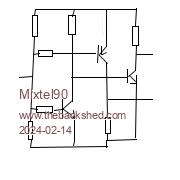
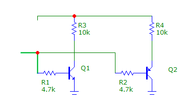
My second sketch works by turning both the first NPN and the PNP on when the pico output is floating. When it goes high it turns the PNP off, when low it turns the first NPN off. The signal at the collector of the first NPN is inverted by the second NPN. The PD on the output of the pico is needed so that the bases of the transistors don't float to a supply rail. - you have to define the midpoint. I think it's more or less as you describe, but I've used base resistors rather than diodes because the base current needs to be limited when the input is either low or high. It's easier to sense when the input is within Vbe of a supply rail than when it's at some point either side of mid supply, that's why I've got both transistors biased on normally. Mick Zilog Inside! nascom.info for Nascom & Gemini Preliminary MMBasic docs & my PCB designs |
||||
| bigmik Guru Joined: 20/06/2011 Location: AustraliaPosts: 2870 |
GDay Peter, All, IF you can get a level that both outputs would be HIGH could you not have a pullup/pull down resistor pair to set the appropriate voltage level and set the CS pin as an INPUT until needed? Regards, Mick Mick's uMite Stuff can be found >>> HERE (Kindly hosted by Dontronics) <<< |
||||
| Turbo46 Guru Joined: 24/12/2017 Location: AustraliaPosts: 1595 |
I can't think of a simple way to do it with diodes. Jim's circuit will sort of work but because Q2 is used as an emitter follower it won't give a good logic zero. My approach is much the same as Mixtel's but I prefer the transistor base drive circuit for Q2 and Q4 in my version. The transistors can be whatever small signal type you have to hand. If you need more drive then reduce R6 and R7 to as low as 1k and below. R1 and R4 may be dispensed with if the input signal has good logic high and low levels which is most likely the case. 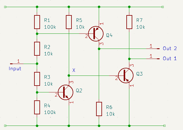 Truth Table IN X 1 2 Hiz 0 1 1 0 1 0 1 1 0 1 0 Bill Keep safe. Live long and prosper. |
||||
| matherp Guru Joined: 11/12/2012 Location: United KingdomPosts: 8603 |
Thanks all, I'll breadboard something up and see if I can get it working. Then I would need to modify the firmware to allow a shared CS pin. |
||||
| Mixtel90 Guru Joined: 05/10/2019 Location: United KingdomPosts: 5768 |
That's neat, Bill. I hadn't considered that approach. :) I'm not sure about removing R1 and R4 as, with a tri-stated input the input voltage isn't defined and will probably drift with temperature. Whether it could drift far enough to give problems I don't know, but with digital noise as well... Mick Zilog Inside! nascom.info for Nascom & Gemini Preliminary MMBasic docs & my PCB designs |
||||
| Volhout Guru Joined: 05/03/2018 Location: NetherlandsPosts: 3585 |
Peter, Bill, The circuit works when you change Q3 into an NPN transistor. But the circuit has a delay of roughly 1.5us (using 10pF loads at both input and output, which is close to layout and pin capacitance). So after you enable the appropriate CS, you need to wait 2us, before actually doing something with that device. You may be able to improve that 10 fold by changing all resistors from 100k-> 10k and 10k->1k. But it will never be as fast as a logic gate, like the proposed 74LVC1G18. That is seemless. Regards, Volhout 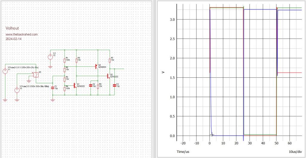 Edited 2024-02-14 18:40 by Volhout PicomiteVGA PETSCII ROBOTS |
||||
| Turbo46 Guru Joined: 24/12/2017 Location: AustraliaPosts: 1595 |
@Mick, thanks Mick, I think the 10k resistors should swamp any leakage from the tri-state output. @harm. Oops, I used the wrong symbol for Q3  . There will be propagation delays with any circuit. The proof of the pudding will be in the eating. . There will be propagation delays with any circuit. The proof of the pudding will be in the eating.Bill Keep safe. Live long and prosper. |
||||
| matherp Guru Joined: 11/12/2012 Location: United KingdomPosts: 8603 |
Works perfectly. I've substituted 1k for all 10K and 10K for all 100K Three output states from one pin  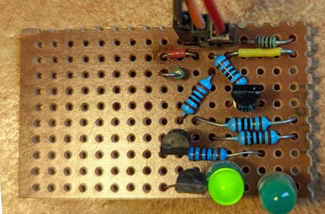  Many thanks for the input Edited 2024-02-14 22:04 by matherp |
||||
| stanleyella Guru Joined: 25/06/2022 Location: United KingdomPosts: 1655 |
Nice one. I didn't realise hi,lo,float half supply for tri site. |
||||
| matherp Guru Joined: 11/12/2012 Location: United KingdomPosts: 8603 |
Here is what a board might look like. Supports 4.3" SSD1963 (and any other SSD1963 with overhang) 3.97" 800x480 IPS displays 34-pin ILI9341 displays 40 pin ILI9341 display Schematic bde38fd7-b56e-4340-ba71-1b6a072ef435.pdf The I/O header has 16 digital I/O from the port expanders + 2*System I2C + 2 GND and 4 power 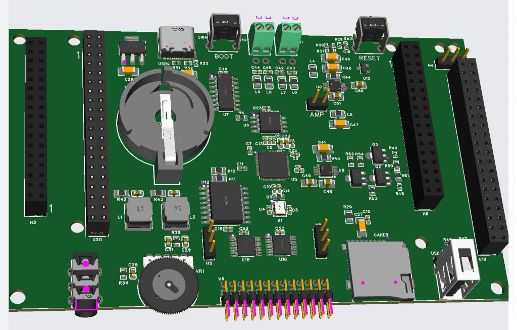 Edited 2024-02-15 05:59 by matherp |
||||
| Volhout Guru Joined: 05/03/2018 Location: NetherlandsPosts: 3585 |
Hi Peter, 1/ I noticed you used SOT89 packages for the transistors. SOT23 or SC70 packages are typically cheaper. 2/ The I2C I/O Is it your intention to create a CSUB to seemless integrate the 16 IO pins into MMBasic ? Alternatively we could write functions SPIN() and SPORT() and commands SPIN and SPORT that are the counterparts of PIN() and PORT() in MMBasic, and store thos in a library. Maybe we could even write a SSETPIN function to set data direction in MMBasic. I think we should not suggest to implement bitbang'ed serial protocols on the I2C IO pins. Volhout P.S. What is the application that you see for this board ? You have high speed and high resolution graphics but for I/O you rely on relatively slow parallel interface. But on board audio amplifiers. This could be a game platform (gameboy++) or a terminal ? As an industrial controller it would be less suited, you would need significantly more communication ports. Edited 2024-02-15 17:58 by Volhout PicomiteVGA PETSCII ROBOTS |
||||
| Mixtel90 Guru Joined: 05/10/2019 Location: United KingdomPosts: 5768 |
If there is PCB space how about using 5.08mm pitch pluggable terminals for the speakers? I realise that they are a little more expensive, but it's probably worth it if the board is to be cased (or even moved off the bench now and again). JLC would only need to supply the fixed part of the connector, obviously. @Volhout All you need to do as an industrial controller is to stick RS485 on the GPIO pins and run MBUS. It's been handling a few thousand IO spread over a km or so for several years now. :) . Edited 2024-02-16 04:08 by Mixtel90 Mick Zilog Inside! nascom.info for Nascom & Gemini Preliminary MMBasic docs & my PCB designs |
||||
| matherp Guru Joined: 11/12/2012 Location: United KingdomPosts: 8603 |
Here is the final version that I'm sending for production. SCH_Schematic1_2024-02-17.pdf I've left off most of the through hole components to keep cost down - as well as the expensive DS3231. As before, I'll order 5. If they work OK and anyone wants one then the cost as pictured will be about £23 + my shipping cost (£1.95 to the UK and £3.25 to Europe). The objective of this board is to provide the maximum possible performance from The RP2040 with a TFT display. Currently CLS @ 480x272 RGB565 pixels takes just over 5mSec @ 378MHz = 52Mbytes/second. The board is intended to be used with USB peripherals but also includes 16-bits of digital I/O using I2C port expander chips. Support for these will be included in the MMBasic firmware using the DEVICE command and functions. The final picture shows the displays which have been fully tested in 16-bit mode. In addition all other SSD1963 displays should work perfectly. The PCB itself is 4-layer and exactly the same size as a 4.3" SSD1963 display. These have reduced in price now chips are available again and are a superb fast display.If this board gets some interest then there are some tricks with the 4.3" display that can be included in firmware - how does 3 full RGB565 framebuffers with instant switching between them sound? See here 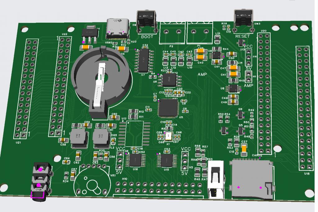 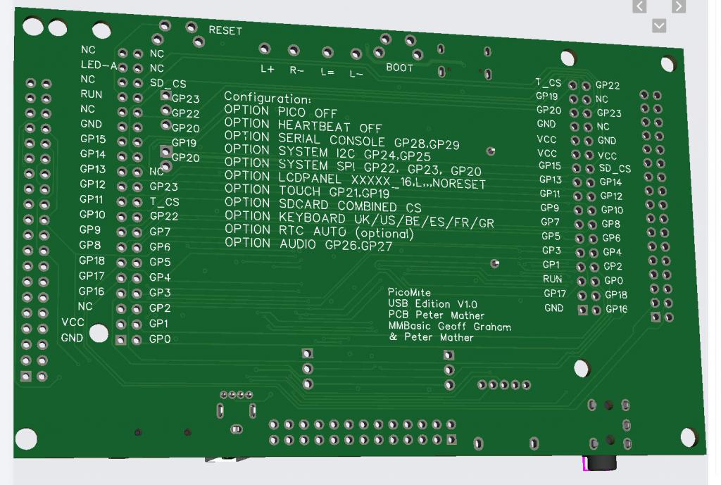 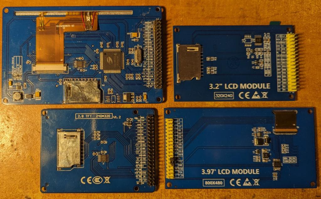 Edited 2024-02-18 03:56 by matherp |
||||
| crazycloud Newbie Joined: 20/08/2023 Location: United StatesPosts: 37 |
Great design. I could really put it to use. can you sell to the USA? |
||||
| matherp Guru Joined: 11/12/2012 Location: United KingdomPosts: 8603 |
No problem. Worst case postage would be about £6.75 untracked |
||||
