
|
|
Forum Index : Electronics : Wiseguy New Inverter Build Nano R6
| Author | Message | ||||
| wiseguy Guru Joined: 21/06/2018 Location: AustraliaPosts: 1206 |
I will not promise anything but I am curious to see what might be required to make it work with a Nano controller. Re postage to UK I will check into it and the customs forms etc required & cost. There are other solutions available which I will discuss with you via email or PMs. I am curious, what do you expect postage cost to UK would/might be - a rough guess is fine, it just helps clarify what method we might use. Not sure if there are any MPPT controllers kicking around - lets see if anyone offers up a couple. Maybe Poida has some spare..... If at first you dont succeed, I suggest you avoid sky diving.... Cheers Mike |
||||
| Murphy's friend Guru Joined: 04/10/2019 Location: AustraliaPosts: 671 |
Thank you for the variac explanation Mike, I do have a variac here (the transformer variety) but was not sure what you meant with that word in regard to the control card. Now, I do like to copy your ideas (I hope you don't mind) and when I saw your interesting use of a 'current type voltage transformer' for sensing the AC mains voltage I thought I'll have to try this. So I laid out a control PCB with this instead of the original LT1638 that Poida used. But I'm curious if this will work with the original Nano program? I'm using your early version of the MC74AC86 gate drive BTW. I'm not interested in many of the features your latest control card offers (have external fan temperature controllers and no need for automatic start up or a status display monitor. I finished the PCB layout but have not sent it for manufacturing yet until I know if my original Nano works with your AC sensing or if I require a different program. Thanks |
||||
| wiseguy Guru Joined: 21/06/2018 Location: AustraliaPosts: 1206 |
Klaus you are welcome to email me a copy of your schematic so I can comment - in short I believe it should work with normal Nano code. If at first you dont succeed, I suggest you avoid sky diving.... Cheers Mike |
||||
| Murphy's friend Guru Joined: 04/10/2019 Location: AustraliaPosts: 671 |
Thanks Mike, email sent to m...s@a...m.com.au I hope this is still correct |
||||
| wiseguy Guru Joined: 21/06/2018 Location: AustraliaPosts: 1206 |
Ok the Variac boards are back, I built one up and it seems to work superbly first time. I have a pretty good energy meter which gives RMS volts Amps and true Watts. Once calibrated, the Variac V & A tracked the energy meter within 10mA (only up to 4A tested) and 1V. The 1 V is because it only has whole digits no decimal places but even 1V in 240 is about 0.4% or better, from a setting of a few volts to 240V very accurate. I plugged in an inductive type Fan that showed 230mA of current but the energy meter has it as 200mA so as predicted the accuracy for reactive loads will be poorer, resistive loads should be spot on. The offset at the bottom end for V & A can be tweaked when calibrating for best accuracy. ie set the volts to a few volts and tweak the offset so it reads the same as the reference meter and then check the top end again and as needed enter the max value in the on screen menu. So time to call for interest in sets of PCBs - I have the following shows of interest to date. If there are any changes to the list its fine just let me know. I expect that I will give it at least a week or so before placing any orders. In the interim I will prepare the BOMs etc with all the final component values - the original BOMs are still 95% accurate - a few added parts and a few resistor value tweaks though. I will also post final schematics and BOMs etc in a couple of days - have some other tasks to get done first so maybe Tuesday. The board sets and part numbers are as described near the bottom of page 4 of this thread. Member name Given Name Inverter Variac Controller only KeepIS Michael 1 3 Disco4now Gerry 2 1 Cobbler Michael 5 Bryan1 Bryan 2 1 RogerDW Roger 2 1 mab1 Marcus 1 1 PM's are probably the best way to indicate what you are after and the quantity. Edited 2024-05-18 23:17 by wiseguy If at first you dont succeed, I suggest you avoid sky diving.... Cheers Mike |
||||
| KeepIS Guru Joined: 13/10/2014 Location: AustraliaPosts: 1866 |
Hi Mike, can you modify my order as follows: 3 Variac 1 Inverter 3 Controllers I can see me having a lot of fun with the Variac design  Thanks  NANO Inverter: Full download - Only Hex Ver 8.1Ks |
||||
| wiseguy Guru Joined: 21/06/2018 Location: AustraliaPosts: 1206 |
Sure Michael, order modified. Ok time to bite the bullet and ask for quantities of MPPT + Brain-board orders. I suspect that a few of the inverter guys (yes you too MAB) are probably after some MPPT boards so I think it makes sense for me to order some if required and consolidate the freight for Inverter/Variac requirements to include MPPT boards at the same time if you want them. If others just want MPPT boards preferably within Australia just PM me with quantity. Cost should be similar to last order and I am guessing ~$15 ea ?? (Poida ordered the last lot). Still working on BOMs schematics PCBs etc. I'm wishing I hadn't retired so I could go back to work for a rest..... If at first you dont succeed, I suggest you avoid sky diving.... Cheers Mike |
||||
| nickskethisniks Guru Joined: 17/10/2017 Location: BelgiumPosts: 462 |
I've sent a pm. |
||||
| wiseguy Guru Joined: 21/06/2018 Location: AustraliaPosts: 1206 |
Sorry for the delays this is turning out bigger than Ben Hur at my end. Main issues were the switching Power supply regulator I designed in from Mornsun (18-75V to 12V 0.5A) at a great price from Digikey, disappeared overnight about a week ago, also from Mouser and a few other suppliers. Turns out they were being used in Russian Aero applications so USA sanctioned Mornsun and everyone stopped supply. Even to clear existing stocks that they had local orders for they just stopped shipping until further notice (dont hold your breath for them...) I thought it was single sourced but it turns out Gaptec do a similar device as a compatible unit also from Digikey so problem solved. The Mornsun part was still available from Element14 last time I looked. I used Phoenix style pluggable connectors on my circuit boards as I have lots in stock, however when preparing the BOM and trying to find cost effective suppliers and part numbers the screw connector plugs for them are expensive at ~$7.50 ea. I figure that when plugging and unplugging the PCB it simplifies service and there is no chance of mis-wiring as the wires stay in the screwed part. However for those that are happy to just use a PCB fixed screw terminal connector it would be a cheaper solution. Here are the 2 BOMs & schematics for the inverter and Variac controller PCBs including the LCD interface PCB. I do not expect any changes to these BOMs going forward the prototypes are working just fine. BOM Inverter Controller Nano Rev7.pdf Schematic Inverter Nano R7.pdf BOM Variac Nano Controller Rev2.pdf Schematic VariacNano R2.pdf I will add the other BOMs over the next few days as time presents and I expect the PCB order quantities will be finalised by ~ Friday 31st A few quick comments about the schematics. The inverse opto drive scheme has always relied on availability of the higher current outputs of the 74ACS and 74ACT and other higher current output quad exclusive or devices that can supply around 20mA of drive. These higher current parts are becoming harder to source but the 74HC86 parts should be around for a longer time even if a SMD part to Dip mini interface pcb is required. Previously I added 8 transistors of buffered outputs that were used with the 74HC86 device but they had a disadvantage that the p-p drive was reduced by ~ 1.3V due to the 2 x VBE losses of the transistors. So I have designed in 2 x 3A LED drivers which are a simple bulletproof drive solution. The TC4424 type buffers I used as buffers have at least 3A drive current with rail to rail 5V outputs. If desired they can also buffer the high current Quad exclusive or gate devices for superior drive outputs & reducing any strain on the logic gates. The capability of the buffers is way overkill, but the TC4424 & HX4424 type devices can be sourced from LCSC for ~ 30 odd cents each. This also removes an error source when substituting buffer transistors with their sometimes reversed pin outs. Lastly I have received some requests for a controller board with a view to experimenting with them as a replacement for EGS002 style controllers so the increased robust drive outputs may help with this application. I decided to up the Revisions to Rev7 for the inverter controller and Rev2 for the Variac controller to differentiate them from the earlier BOM & Schematic posts Edited 2024-05-26 10:36 by wiseguy If at first you dont succeed, I suggest you avoid sky diving.... Cheers Mike |
||||
| wiseguy Guru Joined: 21/06/2018 Location: AustraliaPosts: 1206 |
KeepIS recently advised me to say that the HY5608's are currently on the endangered list and LCSC has run dry. Apparently, there are other suppliers, but they are charging a lot more and my best advice is to steer well clear of other Vendors. My track record of buying semiconductors from Ali Express is that they are nearly all fakes and if you do find some genuine product, someone over there made a serious mistake. They must roll around laughing each time some poor sucker orders their semiconductors, rather fitting "semi" meaning almost, but not quite the real thing. There are other devices from LCSC that could be considered. First for the Variac power PCB the old HY4008 is quite suitable for typical Variac applications up to 1kW and should handle peaks of 2 - 2.5kW without issue. The list of substitutes where there is currently stock available from LCSC at the time of posting is below. Please note that I have only tested HY5608's and HY4008's the ranking I used below were based on specifications from highest to lowest preference. For the 48 volt types 1) to 5) and even 6 are probably good choices for a 5KW inverter. There are also devices very suitable for 24V systems such as: 1)---SE40300GTS--------40V---288A---2.0 mOhm---$1.00 @ 30 off 2)---HY4504W-------------40V---250A---2.4 mOhm---$0.99 @ 30 off For 48 volt systems 1)---HY5608W-------------80V---360A---1.5 mOhm---$1.42 @ 30 off (currently nil stock) I have emailed them re lead time 2)---HY5208W--------------80V---320A---2.0 mOhm---$1.34 @ 30 off 3)---HY5110W-------------100V--295A---2.4 mOhm---$1.41 @ 30 off 4)---Hy5012W--------------125V--300A---2.9 mOhm---$1.34 @ 30 off 5)---GT016N10Q----------100V--288A---1.65mOhm---$1.25 @ 30 off 6)---SP010N02BGHTF---150V--235A---2.0 mohm---$1.20 @ 30 off 7)---SP010N03BGHTF---100V--210A---3.2 mohm---$0.67 @ 30 off 8)---HY4008W---------------80V---200A---3.5 mohm---$0.84 @ 30 off Edited 2024-05-27 21:21 by wiseguy If at first you dont succeed, I suggest you avoid sky diving.... Cheers Mike |
||||
| wiseguy Guru Joined: 21/06/2018 Location: AustraliaPosts: 1206 |
At around midnight last night I finally had uploaded 8 different circuit boards at JLPCB. So almost ready to pull the trigger and pay for them. Luckily I remembered this morning to add some MPPT Power & MPPT Brain boards to the order which I had forgotten to do whilst half asleep, and to up the quantity for the extra controllers some had asked for. I can honestly say that this whole process has caused an immense amount of self induced stress, its one thing to order something for my self and if I make a mistake its just a few dollars and a small annoyance. But when making an order to the tune of $700 odd dollars and knowing that everyone expects (rightfully so) that it is cookie cutter electronics and they should just work first time the attention to detail over the correctness of the boards etc really got to me. Some of the changes I have made include provision for the inverter power PCB to accept 3 different types of DC/DC modules the 4 Pin sip 1W all use a common pin out but the 12/15 and 12/12 units either use pins 1,2 & 4,6 or 1,2 & 5,7 so now the PCB accepts all 3 types. Revlac pointed out that the FOD3182s (opto gate drivers) are available in SMD for less than 50c so I created a small PCB (11mm x 11.2mm) for the 8pin SMD to 8 pin DIP. I will include 4 little PCBs with each Inverter and each Variac power PCB. Then I had to make room on the inverter power PCB to ensure the little SMD to DIP PCBs had enough room. I also removed the other unused components that needed links to be put in etc so building them will be simpler now and possibly able to use some parts in your collections. I have made similar changes to the Variac board to accept a different DC/DC converter and the SMD/Dip interface boards. Disco4now asked me to include 2 extra capacitor boards with his inverter orders so he can solder some smaller value Caps in them just for testing purposes that wont vaporise stuff due to immense surge currents. I liked the idea so much I decided to increase the Bulk Capacitor PCB orders so everyone who orders at least 1 inverter will get 2 extra capacitor PCBs - I hope you are all ok with that. I will also supply an LCD interface PCB with every inverter/variac/extra Nano controller and MPPT board sets. I expect to pay for the order by late tomorrow or Monday at the latest so it wont be long now ~ 7-10 days and then the next phase begins. Everyone who has placed an order for PCBs but no address (most of you lol) can you now please pm me with your postal addresses. For payment I believe I can send a simple paypal money request via email so please include a private email address with your street address so I can send the bills out. This method as I found out with Dex is foolproof and cheaper and faster and more reliable than using banks - we found out the hard way how not to do it. If at first you dont succeed, I suggest you avoid sky diving.... Cheers Mike |
||||
| KeepIS Guru Joined: 13/10/2014 Location: AustraliaPosts: 1866 |
Thanks for all that work, I think you push yourself to much, this is after all, a hobby group, I'm sure most of us are understanding of some hiccups. FYI I have my early version solder in cap boards loaded with around 2000uf each, very nice way to test the inverter after the first few power cycles with no Caps. The layout changes for various component availability is a great idea, and it looks like it was worth the wait to finalize the layout as some of the parts are only now showing up as short supply. NANO Inverter: Full download - Only Hex Ver 8.1Ks |
||||
| poida Guru Joined: 02/02/2017 Location: AustraliaPosts: 1432 |
It's one thing to see amateur people do a few things (think: me) and deliver a result that sort of works, if you hold your tongue right and have a coupl'a beers and accept fireworks and stuff. It's an entirely other thing to to have an E.E. of many decades offering a solution. This is Wiseguy. His inverter design is going to kick ass and it will not blow up. It has most excellent FET Gate drive and there is NO shoot through at all. Not even a tiny bit. This is the best I have ever seen. I am lucky to be involved in a professional project. If you want a good inverter, I would go for this project. It's just going to run and run and ran for years. wronger than a phone book full of wrong phone numbers |
||||
| wiseguy Guru Joined: 21/06/2018 Location: AustraliaPosts: 1206 |
Well, that is a very nice vote of confidence thanks Poida, maybe a little premature though but time will tell. If others can get something running even half as well as KeepIS's inverter it could be regarded as a reasonable success I reckon. One of the mantras hanging in our R&D lab many (~40) years ago was "It is easy to improve on what already exists". FET and power switching & switch-mode technology has formed a very large part of my later career. The Oztules/Mad inverter had a mixed success outcome, some you couldnt kill others you killed it randomly seemingly for no reason. I had almost no first-hand experience with SPWM inverters but have never shied from a good challenge, this has become yet another late career change I guess, but the money sure sucks! After you created code for my version of a sinewave converter and we tied it to the inverse opto drive system that Warpspeed promoted, I proved that an EG8010 or a Nano controller could both work very successfully with my inverse Opto buffered implementation. So like Edison who when asked about failing to make a light globe after 100 failed prototypes replied, I have not failed, I have just learned 100 ways not to make a lamp. I also looked at what did not work and just tried to improve on it, time and feedback will be the real arbiter of success or otherwise. I paid ~$725 for all the boards today about $166 was freight, so I hope everyone can afford them lol, there are essentially 12 takers some want 4 so it wont be too scary. Edited 2024-06-02 20:23 by wiseguy If at first you dont succeed, I suggest you avoid sky diving.... Cheers Mike |
||||
| wiseguy Guru Joined: 21/06/2018 Location: AustraliaPosts: 1206 |
Working out a fair charge to everyone was a bit of an exercise. For anyone interested the JLPCB freight was actually $176 and goods $550 both rounded up to the nearest $. The weight of an inverter board or MPPT board was 3 times the weight of the controller or capacitor boards. So I applied a weighting factor of 3 for the Inverter and MPPT boards and 1 for the other boards. Next was individual boards total cost and number required to arrive at a per board cost. Then add the sets together with the weighting cost so you are charged by proportion of weight for freight + the portion of goods costs ordered. Inverter Set came to $13 (my original budget estimate was $16) but + $5 for portion of JL freight so it will be $18 per Inverter set. Variac Set came to $7.50 and with JL post $2.50 ie $9 per variac set The sets also include the LCD meter and 4 SMD to 8 pin DIP pcbs per power board Post worked out at 83C per weight factor of 1 (ie a controller PCB) Local post will have to be added along with another $5.00 for the 2 extra capacitor boards with each order of at least 1 inverter. As initially promised, I will include a current sense transformer for each Inverter/Variac order ie 4 Inverters and 2 variacs = 6 current sense transformers. The MPPT boards are $15.50 including the LCD & Nano PCB & JL freight The next part is to work out the Aus postage mostly local to your destinations. So, the cost of a small satchel allows for 5kg @ 10.90 and 2-5 day delivery Express post 1-2 days for 5Kg @ $14.40 (extra $3.50) I will choose express post for all then I can calculate total cost including shipping locally and request payment in the next day or so. If anyone is not happy with express post just take $3.50 off the total and let me know by PM within the next week and I will use standard post. Edited 2024-06-03 15:54 by wiseguy If at first you dont succeed, I suggest you avoid sky diving.... Cheers Mike |
||||
| KeepIS Guru Joined: 13/10/2014 Location: AustraliaPosts: 1866 |
 NANO Inverter: Full download - Only Hex Ver 8.1Ks |
||||
| wiseguy Guru Joined: 21/06/2018 Location: AustraliaPosts: 1206 |
I decided to post the information so everyone can see where the costs went, I am out 13c which I am more than happy to pay! Here is the spreadsheet of who/orders and costs - it makes sense to me which is important, but if anyone wants more explanation though happy to oblige. Project info.pdf Please note the cost less shipping refers to less the local shipping, JL shipping portion is already included Here is my paypal payment slip for the order ( Image removed at request of poster. Gizmo ) The grey matter let me down, in my head I rounded it to $725 so Im not down by ~13c I am actually up by 33c whohoo who said this job doesn't pay.....Also the column of SMD/Dip a quantity of 1 = 8 small PCBs so 1.5 = 12 small pcbs Tomorrow I will send the Paypal requests, which are more important for overseas payments, however if anyone prefers to do a bank transfer locally to save I think it is a 1% levy please pm me and I will send you my bank details. Edited 2024-06-08 18:09 by Gizmo If at first you dont succeed, I suggest you avoid sky diving.... Cheers Mike |
||||
| wiseguy Guru Joined: 21/06/2018 Location: AustraliaPosts: 1206 |
Paperwork sheesh I'm sick of it already....I will post the current schematics assemblies BOMs etc, these will all have an issue date please ignore previous documents. Hopefully I can have a rest for a few days until the onslaught of the PCBs rains on me. There may be errors (hope not) I was going cross eyed by the time this lot was finished 5KW Inverter & controller Documents. WG39Rev7 Schematic.pdf WG39R7 Assy.pdf WG39R7 & WG44R2 BOM.pdf WG30Rev2 Schematic.pdf WG30R2 Assy.pdf 5KW WG30R2 & WG06R1 BOM.pdf FET to Heatsink Mount.pdf Variac documents WG40R1 Schematic.pdf WG41R1 Schematic.pdf WG40R1 & WG41R1 BOM.pdf WG40R1 & WG41R1 Assy.pdf FET to Heatsink Mount.pdf Nano LCD WG44Rev2 Schematic.pdf WG44Rev2 Assembly Issue 040624.pdf Edited 2024-06-04 18:37 by wiseguy If at first you dont succeed, I suggest you avoid sky diving.... Cheers Mike |
||||
| wiseguy Guru Joined: 21/06/2018 Location: AustraliaPosts: 1206 |
This was also posted on KeepIS's thread but really belongs here. Have had a total rethink of the startup stragedy oops strategy. The main problem was caused by the slow shutdown introduced by the main capacitor bank and the regulators behaviour as the capacitors slowly drain & even recover briefly with the bad effects to both Nanos. So the proposed on/off 48V startup circuit is a 2 pronged approach that I believe will solve the problems with minimal work (card mods) involved. The new scheme stops the main capacitor bank from continuing to feed power to the control card when the on/off switch is set to off. Further the switch being set to "off" crowbars the 12V & 5V supplies to ground (be nice through a 1R-4R7 resistor) so the 5 & 12V supplies get a whoa camel moment (instantly stopped) so the control card and LCD 5V are instantly stopped. The card mods required is to leave off Q10 R27 R28 and C28 and on the card put a link where R27 & R28 were to short the previous "Stop" card connection to ground. Of course the off position of the switch could also be connected to a convenient ground nearby, it does not have to connect to the card ground but on the card is my recommendation. 1) Change the precharge resistor/diode & Contactor-feed wiring as per start up schematic. 2) Remove (or dont install) Q10, R27, R28 & C28. 3) fit 3 diodes and 1 resistor to card - easy using breadboard area (1 cut track). Edit: Maybe rethink the DB shorting the 12V to ground is not really needed & probably overkill. 4) instead of a link fit a connector and wires to J11 for a new run stop switch. To start the inverter it wont matter which position the run/stop switch is in. To stop the inverter though the run/stop switch should be set to stop first and then when the green led is not flashing now turn the on/off switch to off. If the inverter is on with the run/stop switch set to run, the auto shutdown on low battery and auto restart when battery voltage rises again is all unaffected. if the batteries get to ~7V with the on/off switch still set to on I think you have greater problems than Nano code corruption. Control Card Mods - only 1 track to cut (Note: the 48V is now switched to ground when on/off is set to off) 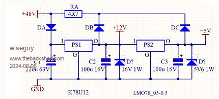 Start up wiring Mods. Auto Start Mod.pdf I look forward to feedback about issues I missed or and .whether this scheme is liked or not. Dex, in retrospect your suggestion about an SCR crowbarring the 5V is not too dissimilar to this scheme that I eventually arrived at. But this way leaves the "crowbar" decision to a human not a micro which had no spare pins anyway (Note pin A7 is grounded but not spare it is used to solve an issue with the A/D in the Nano causing low end offset issues) and I felt it had an element of risk associated with it that I did not like. It also removed the stored energy in the bulk capacitors from the control card. Lastly if the LCD ever plays up there is an option to ground pin2 of J8 via a diode to the 48V point that is switched to ground with the inverter off, which will also kill any output via the serial line to the LCD. From my perspective, in the absence of any negative issues or glitches I have overlooked, or feedback with a better solution, I will consider the amnesia problem as hardware solved and will update the startup drawings Boms and Mods in the next day or so. This does not preclude a belts and braces approach to also include the hex code upload KeepIS has created with no boot loader but it should work with standard code too. PS Mike I see you treading on egg shells now lol Edited 2024-06-06 12:53 by wiseguy If at first you dont succeed, I suggest you avoid sky diving.... Cheers Mike |
||||
| KeepIS Guru Joined: 13/10/2014 Location: AustraliaPosts: 1866 |
Hi Mike, just got back to the PC. A clarification if I may: The boot-loader is a separate piece of code, it is usually programmed into the Arduino and other boards, but not always. So yes, there is no change to the standard code or my code version, both are independent of the boot-loader, or lack thereof. The Boot-loader is also supplied with the Arduino IDE, it can be program back in at any time, or removed. You need a small programmer board, these are available everywhere and cost from $7 to $18, with this you can upload HEX files into the Nano, program the boot-loader back in and much more. The Arduino IDE cater for this small board. Now I just need to look at the Auto wiring and hardware changes to see what ripple effects it may have. NANO Inverter: Full download - Only Hex Ver 8.1Ks |
||||
| The Back Shed's forum code is written, and hosted, in Australia. | © JAQ Software 2025 |
