
|
|
Forum Index : Electronics : My generator/inverter project ....
| Author | Message | ||||
| ramblin Newbie Joined: 26/03/2024 Location: United StatesPosts: 39 |
Just about everything I posted before WAS wrong and I have not found a way to delete it. I have everything now exactly as the example "wiseguy" posted for me. The only changes I made are noted in my last post. I`m sure I have it all wired correctly now. I get good results up to 150vdc input. |
||||
| wiseguy Guru Joined: 21/06/2018 Location: AustraliaPosts: 1206 |
Now is the time to implement the EGS002 changes for their less thanperfect overcurrent behaviour. I will post some links later if you need them - as I have ties for the next day or so but their is plenty of information on the BS and the net on what changes need to be made if you do some searches. There are products out there that use the EGS002 and they apparently work well without the mods being made, there must be a secret about how they do it. But as you have found like many others here that the mods are required to stop FETs blowing. If at first you dont succeed, I suggest you avoid sky diving.... Cheers Mike |
||||
| ramblin Newbie Joined: 26/03/2024 Location: United StatesPosts: 39 |
I believe this is accurate now. |
||||
| nickskethisniks Guru Joined: 17/10/2017 Location: BelgiumPosts: 462 |
Ok, sorry, my bad, I forgot that part apparently... Did the irf740 mosfets blow without load? Maybe your layout is not optimal (you can't expect good things when combining power and high frequencies on a protoboard) that there are high voltage spikes over drain/source or on the gates. Chance is that higher voltage rated mosfets could survive that, but this would not take away the cause. You want to probe the gate/source and drain/source of the mosfets, also look for cross conduction but this will be hard without the right tools. |
||||
| ramblin Newbie Joined: 26/03/2024 Location: United StatesPosts: 39 |
I blew all my 46NF30 and IRF740s with a load and without. The IRFP460n were just a cheap ebay find and I have not tried them yet but would expect to blow them too if I don`t solve my problem 1st. I have learned so much just on this thread and my component placement is far from ideal. No doubt I have a lot of cross conduction. I might just start all over and build it right this time. I was looking for something simple to just play around with my gen project but if I can`t make it work I would try a wiseguy build or a ozinverter or something else. Maybe use a transformer. I`m open to all suggestions from all here. |
||||
| wiseguy Guru Joined: 21/06/2018 Location: AustraliaPosts: 1206 |
Poida showed what he did to the EGS002 card to stop it blowing mosfets here I would not give up yet without first trying the EGS002 Mods. There is another entry by "Tinker" now Murphy Friend on how to Mod the card - I can't advise if they are the same or if one is better than the other - I have never modded a card. Tinker mods are here So hopefully someone else can advise you of the best method to make your EGS002 FET friendly. Whilst your breadboard may not be the neatest, I do not believe it is what is stopping you from generating AC instead of just dead FETs. If at first you dont succeed, I suggest you avoid sky diving.... Cheers Mike |
||||
| ramblin Newbie Joined: 26/03/2024 Location: United StatesPosts: 39 |
I took your advise and did find much info on other sites dealing with issues like mine. I have a notepad full of things to try and ways to test I was unaware of. I will study the links you provided and the next time I post I will know more based on newly acquired info. Keep the advise coming. I pay attention. Thanks everyone ! |
||||
| analog8484 Senior Member Joined: 11/11/2021 Location: United StatesPosts: 146 |
If FET's are blowing without a load consistently then it's possible the dead-time is too short for the FET's. Perhaps you should set the dead-time on the egs002 to max for now. It's difficult to know for sure unless you can scope the uppper and lower FET's simultaneously. Also, be aware that, unlike the common usage of egs002 on this forum, you are using it for direct high voltage switching which is risky given that there is not adequate creepage and clearance between the high and low voltage pins. Edited 2024-05-12 04:52 by analog8484 |
||||
| ramblin Newbie Joined: 26/03/2024 Location: United StatesPosts: 39 |
Much good news to report for today. After unsoldering a few things and testing all my runs with an ohm meter I proceeded with the "poida fix" provided in the link. Bingo.. solved most of my issues. "rusty" told me about this 2 weeks ago but I didn`t have a spare board at the time. Wish I would have done it then, I could have saved myself a few bucks. I am now able to reach my target input voltage of 175-180vdc. Trim pot is to the gnd. side and I have 28vac with a 40watt bulb as a load. Pin15 is at 4.5vdc. Bulb is glowing orange. Slowly, I turn the pot and increase my AC to about 60-65 vac. Bulb is bright, waveform is stable. Nothing getting warm. Pin15 is now at 2.8vdc. Turn the pot more to about 70vac and pin15 is down to just under 2vdc. Go just a little more and pin15 drops to 1.5-1.8vdc and the board shuts down. Haven`t blown a single fet (IRF740) all day. I am certain the remaining issue is in the control circuit now. R19 is at 100K. For R21 I began with a 56K with some control. I tried 68K and it was worse with very little control. I have a 50k in there now. Should I try a 47 or 43K next ? I did quite a bit of testing, although nothing to drastic. Ramp the voltage up and down, applied the load on and off at various voltages. No issues. Max amps never exceeded 1 amp. I would expect thing to heat up a bit as I add more power and load when I get the IRFP460 mosfets. Very encouraging day. Almost there ! |
||||
| Murphy's friend Guru Joined: 04/10/2019 Location: AustraliaPosts: 671 |
Well, that link goes back many years  . I do remember that the EGS002 mod worked well but I would not consider the schematic shown - we, the forum here, have moved on by a long way since back then. . I do remember that the EGS002 mod worked well but I would not consider the schematic shown - we, the forum here, have moved on by a long way since back then.There are still some EGS002 boards in the bottom of my old projects box but I would not dream about using them now. The new inverter designs here are much more reliable (they only blow up if one does something stupid like shorting something)  . . |
||||
| nickskethisniks Guru Joined: 17/10/2017 Location: BelgiumPosts: 462 |
Can you post a picture of the inductor you used? I can't believe changing the resistor will do much at this point. |
||||
| ramblin Newbie Joined: 26/03/2024 Location: United StatesPosts: 39 |
I admit I don`t know a thing about chokes. Bought this one because it will handle 10 amps and was rated 3.3mH. Didn`t know how to hook it up either. Got only 1 side wired in series now. Tried wiring the other side in with jumpers and also bifilar (that totally changed the waveform). This choke is probably wrong. I could make about what ever I need as I got a lot of small ferrite torrids. I just know as I turn the AC voltage higher,pin 15 decreases in voltage till the board drops out. 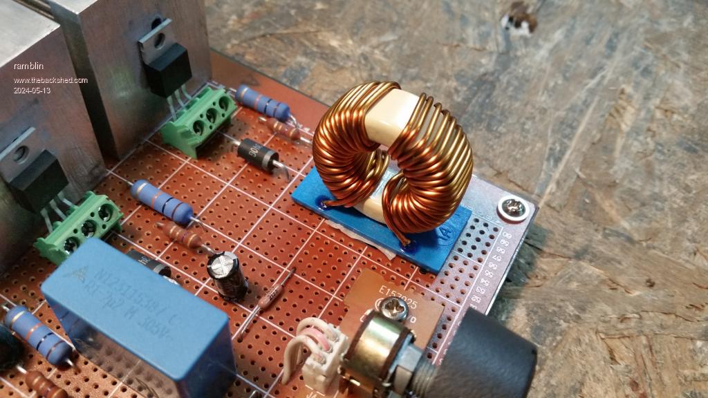 Edited 2024-05-13 01:41 by ramblin |
||||
| nickskethisniks Guru Joined: 17/10/2017 Location: BelgiumPosts: 462 |
It looks like you have a common mode choke, this one will have a very low saturation point/current, they can't store a lot of energy and this function is what you want. So this would probably mean why you are blowing up mosfets. Saturation means no inductance and so just a piece of wire, and high current peaks thru your mosfets as result, because of the 2,2uf on the output, this forms a very low impedance/resistance for the 10khz H-bridge output. Find something with iron powder or better sendust material, or gapped ferrite cores. It has a lot more windings, 100windings are very common most of the time and they can store energy, crude said to fill the gaps of the pwm. Most info on this site about inductors are in the inverter or mppt controller threads, but the used inductance is much lower. This manufacturer has lots of goodies: https://www.micrometals.com/ For example MS-184075-2 is a common used core material used for this kind of application, although 10khz is low and you might better of with a gaped silicon steel core, most often used in grid tied inverters. We would need some numbers to help you make a decision, I think voltage/current output and switching frequency are the mean parameters we need to calculate something for you. Or you said earlier you have some things laying around, look for some cores in a scrap bin and post some pictures, maybe there is something usable. Edited 2024-05-13 06:23 by nickskethisniks |
||||
| ramblin Newbie Joined: 26/03/2024 Location: United StatesPosts: 39 |
I knew I messed up on the choke. With that explanation I see how bad. Most of my surplus are going to be ferrites (lots of ferrites) about the same size as pictured now. But I do have these big ones. (2) 18 ga. steel, 150 strips each, insulated on 1 side, at 1.5 lbs apiece. And this Micrometals, T650-52 powdered iron toroid. On a chance it could be used as is, Its wrapped 1st with 130 turns of 16 ga. solid copper, silver plated, teflon coated wire. 2nd wrap is (3) evenly spaced (120deg.) of 20 ga. solid copper, silver plated, teflon coated, 41 turns each (could be tied together) for total 123 turns. 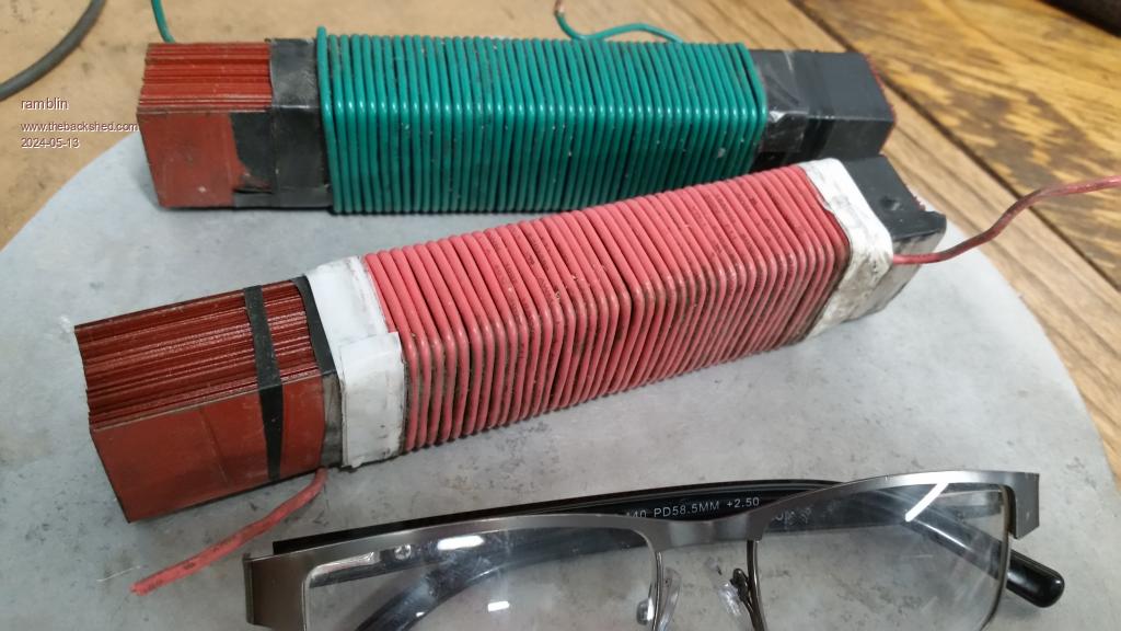 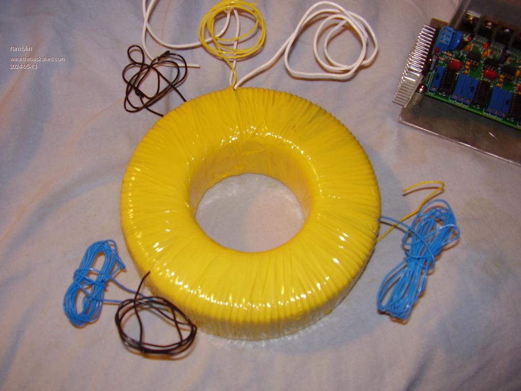 |
||||
| Solar Mike Guru Joined: 08/02/2015 Location: New ZealandPosts: 1162 |
That T650-52 core should work ok, try 10 turns of suitably thick copper wire for the primary current you are expecting, 10T gives approx 40uH. Leave the other wires there disconnected if you want to use them for some other purpose. Cheers Mike |
||||
| nickskethisniks Guru Joined: 17/10/2017 Location: BelgiumPosts: 462 |
That 650 core gives 405nH/n^2, formula is L=405 X n^2 130 windings will give you almost 7mH, 82 windings wil give you 2.7mH Inductance will drop a bit when loaded but the core you have is a monster so this will be peanuts. If your not rewinding it, you could do like mike suggested, wind over the existing windings or use 82 (41+41 in series) windings this will be good for testing. Later on you can try something different this will have probably higher no load losses Vs a smaller (optimised one)because it's 5kg. |
||||
| ramblin Newbie Joined: 26/03/2024 Location: United StatesPosts: 39 |
This is the post I been wanting to write. I now have my inverter up and running with no issues with just a few minor changes. I have a many continuous hours on it running PCs, floodlights, motors, drills and just about anything else I can find to try. I seems, my limitations are due to my own experimental generator which hasn't performed as expected. The best coil configuration to get me to the 175-185 window I need is coming up a little short. On average about 170vdc. That conversion only yields about 108-110vac which is about as high as I can turn up the voltage control before the EGS shuts down and blinks undervoltage. As long as I leave it there, I can do about anything I want as long as I add in coils as I add load. Back when I was testing the gen with "dirty" AC I could get much higher voltage out of the same configuration, but I was using AC run caps on the combined output. Now, with a 1000uf cap on my DC output I will see well over 200 but in the end 550hz @170vdc will get you aboue 108vac. I just don`t see any way around that and may have to just live with it. It is very stable though. I`ve tried everything to trip it up but it just keeps on running. If I carelessly add load without increasing power my voltage will drop and at a point the EGS will shut down. No more burning up fets. Nothing even get warm considering its all wired up with light, cheap jumpers. Several here warned me of this board's limitations. A few had doubts it would even work. I like what Murphy`s friend said, "we, the forum here, have moved on by a long way since back then." The undersized choke I`m using, a T-157-52 with as many turns I could stuff on there is only about 1.8mH. The big 650 toroid allowed me to test many configurations from .880mH thru 7.50mH but voltage suffered. Between 2 and 3mh on a T-157 powdered iron core yielded the highest voltage with good stability. I have a great sendust toroid on order and I think about 2.75 to 3mH will be perfect and should give me some improvement. Also I had a 1000uf electrolytic cap on my DC output for a while, even a 2200uf, as well as 450, 330 and a few others. The little 450uf pictured runs best. I could use some advice here on what would be ideal. Most of my high voltage caps are old from TVs, est. I am very pleased with the way it turned out. Many improvements can still be made. Many here, to many to name spent a lot of time walking me thru this project and I greatly appreciate it. The "hack" provided by "poida" who I don`t think ever commented directly is exceptional and should be sticked if its not already. That alone ended my mosfet wildfires. I tried to cram it all in one pic. Hope you like it ! 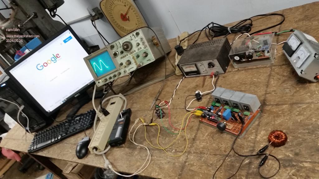 |
||||
| KeepIS Guru Joined: 13/10/2014 Location: AustraliaPosts: 1866 |
Nice work getting it to this stage, I though this might be of some interest to you. I reverse engineered this circuit for a 5KW continuous 10KW peak inverter: The important thing: The input is over 390V DC and output is 240V AC. Obviously, inputs P4 and P8, diodes and all the capacitors after that are to rectify and smooth the output from a Low voltage battery DC input to High voltage AC to power the Sine wave AC output stage. It might be of no interest, but it's using an 8010 board to drive it. It is a powerful inverter. I might still have a picture of the Chokes used if you are interested. Could not post pix as reducing size makes it very hard to read. Link to png file NANO Inverter: Full download - Only Hex Ver 8.1Ks |
||||
| nickskethisniks Guru Joined: 17/10/2017 Location: BelgiumPosts: 462 |
Congrats!  You might want to consider to put more coils parallel (lower voltage) and put a step up transformer on the output to achieve your goals. But the way you did now is the most efficient. Or try out the nanoverter platform to create the pwm signals. You have something working now and I don't want to discourage you but improvements will only be beneficial like for instance reliability, robustness or life span. The more you read up or learn about the subject the more you realise the little you know.  Their is a reason "Chinese" inverters fail after a while and others are build to last. Their is a reason "Chinese" inverters fail after a while and others are build to last. |
||||
| wiseguy Guru Joined: 21/06/2018 Location: AustraliaPosts: 1206 |
I had faith you could & would make it work. The method you used to create the circuit is very similar to dozens of my early prototype creations. Even relatively high power can be achieved this way. Printed circuit boards were so expensive when I used to do this in ~ 1985, to get back 6 prototype PCB samples cost around $400 a large part of the cost was photo tooling. So it paid to get the circuit working on perforated board first and only then make the PCB. These days you can send out a PCB design and have a 100mm x 100mm prototype returned for less than $8 delivered to your door in ~ 10 days, things have certainly changed. Congratulations on getting it working, the satisfaction of achieving that lasts for a long time. Now you too have the bug, may it never leave you...  If at first you dont succeed, I suggest you avoid sky diving.... Cheers Mike |
||||
| The Back Shed's forum code is written, and hosted, in Australia. | © JAQ Software 2025 |
