
|
|
Forum Index : Other Stuff : Axial-flux Generator
| Author | Message | ||||
MacGyver Guru Joined: 12/05/2009 Location: United StatesPosts: 1329 |
Headsup Here's my 2-cent's worth: I'm actually a non-expert when it comes to generators, but I've learned a few things. First off, I think the slightly triangle shape of some coils more closely matches the shape of the magnets used, at least that's what I've garnered from pictures. As far as concentrating flux, the idea is to pass as concentrated an amount of flux through the wires as you can. This is usually accomplished by lessening the distance between the coil surface and the passing magnets. The closer the pass, the greater the flux density. When iron cores are used to maximize flux and provide a flux-return path, "cogging" happens. This is a case of the magnets wanting to stay "stuck" to the iron running through the coils. Each time a magnet passes over an iron core, it kind of "thumps" and that's called cogging. In general, if it cogs heavily, it means the lines of flux are very concentrated. This is good for making electricity, but makes noise and vibration. An "axial-flux" generator (alternator) merely passes the magnets over a series of coils, each of which do not have an iron core. For this reason, there is no start-up torque requirement for the most part, because there is no resistance. As electricity is generated in an axial-flux (ax-fx) generator, the coils generate some induced magnetism and this causes some cogging. Again, this is mechanical resistance and some vibration can occur. In an "axial-flux" design, the lines of flux run from north to south and are parallel with the axis of rotation. In a "radial-flux" situation, those lines of flux run perpendicular to the axis of rotation. Hope this helps a little. I'm sure others will add to this as well. Nothing difficult is ever easy! Perhaps better stated in the words of Morgan Freeman, "Where there is no struggle, there is no progress!" Copeville, Texas |
||||
| Tinker Guru Joined: 07/11/2007 Location: AustraliaPosts: 1904 |
Your question was something I wanted to know a few years ago and I did find a good explanation on a wind generator site somewhere but, alas, can't remember where it was. From memory then, for optimal spacing, when one magnet approaches the outside edge of a coil the previous magnet should just be leaving the far inside edge of the same coil. Magnets alternate N,S,N,S..... The center of the coil should be as large (not smaller) as the magnet face facing it to allow all the magnetic flux lines cut all the windings at right angles. The actual shape of the coil is dictated by what space is available and how the coils fit next to each other. Wire size (area of cross section) only affects its current carrying capacity. The output voltage depends on the number of turns, the speed (RPM) and the strength of the magnetic field. When dealing with magnetic flux do not forget the return path which is often via the iron back plate the magnets fit onto. Re your last statement, for 3 phase AC the number relationship is 4:3 magnets to coils. If you use other ratios you may have to use independent rectification, It may be wise to start experimenting with 3 phase as that is easiest and lots of info is here on this forum. Trying to re invent the wheel may bring disappointment, I learned that the hard way  Klaus |
||||
| GWatPE Senior Member Joined: 01/09/2006 Location: AustraliaPosts: 2127 |
Re: the coil to magnet ratio. the first AxFx alternator I built, has 44magnets and 44 coils arranged in 4phases with essentially 11 individual parts arranged in series. giving 4coils and 4magnets per section. Overlapping coils makes the 4phase possible. requires independent rectification of each phase. Gordon. become more energy aware |
||||
Greenbelt Guru Joined: 11/01/2009 Location: United StatesPosts: 566 |
Posted: 17 January 2010 at 10:32pm | IP Logged Quote HeadsUp small question can someone describe the difference in output between using round coils vs triangular shaped ones ? and why is it so ? Edit;Could not upload 2 images on this post tried 4 times. Editing --No problem 
Time has proven that I am blind to the Obvious, some of the above may be True? |
||||
| Dinges Senior Member Joined: 04/01/2008 Location: AlbaniaPosts: 510 |
Gordon, I think we've talked about this before, but you've got 4 *electrical* phases, at 90 degree shift (0-90-180-270). However, for mechanical loading ('torque ripple') considerations, you have effectively 2 phases, as the peaks of 2 phases (in this case, 0-180 and 90-270) coincide. For least torque ripple, going with simply 3 phases (or 5, or 7, or...) would be a better way to go. When having to choose between a 1, 2, 3, 4 or 5 phase alternator, I would definitely *not* build a 1 phase one. 2 phase (and thus, 4 phase, or any other multiple of 2) would be out of the question too. 3 or 5 would be fine. I think I'd settle for 3. I certainly would prefer 3 over 4 or 2. With 3 phases, you not only benefit from least torque ripple but can also choose between star, delta and independent rectification. [quote=Tinker]Re your last statement, for 3 phase AC the number relationship is 4:3 magnets to coils. If you use other ratios you may have to use independent rectification, It may be wise to start experimenting with 3 phase as that is easiest and lots of info is here on this forum. [/quote] Not necessarily, Tinker; the 4:3 ratio is just a convenient one, that makes building an alternator with non-overlapping coils easy. Other ratios are possible, e.g. 12:18, 14:12, 10:12, etc.etc., still yielding a 3 phase alternator, i.e. without having to resort to independent rectification. http://www.powercroco.de/Kombinationstabelle.html If you look at that table (intended for radial-flux motors, but basically the same idea), you'll see all possible combinations of statornuts and rotor poles that would yield a 3-phase motor. Notice how the 12:9 combination (12 nuten, 9 pole) yields a very simple winding schema: ABCABC. Other combinations yield other schemes, e.g. AbaC... (where a small letter stands for a coil-winding direction opposite to the coils with a capital letter; i.e. some coils are wound (or easier: wired) clockwise, others anti-clockwise. The above may confuse more than enlighten, but is just to show that there's more to it than just the commonly built 4:3 combination. Other combinations can be made to work too. Whether they have advantages? Guess that depends.... not sure for axial fluxes, but I can think of cases for motorconversions or perhaps F&Ps. For example, I still would like to some day build a motorconversion with, say, 36 stator slots and 30 magnetic poles. With motorconversions, it'd be relatively easy to try out these other combinations to get an alternator with many poles (i.e. a slow runner - VAWTs anyone?) but still being 3-phase, with all the advantages that brings with it. Peter. (<-- thinks 'some day' may be a very long way off, considering the backlog of other projects with higher priority) |
||||
| VK4AYQ Guru Joined: 02/12/2009 Location: AustraliaPosts: 2539 |
Hi Macgyver Many years ago I made a number of VSWM for various projects I found the best way to get over the starting problem was a centrifical clutch, I made them from drum brakes with the shoes set in leading configuration with light springs to disengag when the mill stopped and bolted on lead weights to set the cut in speed at 25 rpm the inertia of the rotor overcame the cogging of my alternater with ease it was a 12 magmet 15 coil affair i made myself that had a rectifier on each coil and these where switched in sequentially to maintain rpm of the rotor. Sounds complicated but it was a piviting horizontal wind vane that lifted with wind speed and micro switches switched in the coils sequentially, I am sure it could be done electronically but I had to make it farmer proof, on some I fitted a disk brake for emergency stop hold position. Keep up the good work All the best Bob Foolin Around |
||||
oztules Guru Joined: 26/07/2007 Location: AustraliaPosts: 1686 |
Round coils for round magnets. Square coils for square magnets, triangular(ish) coils when you don't have enough inner circumference room for your square magnet spacing 
Triangular(ish) for wedge shaped coils..... etc. Wrong shapes as you display lead to leakage.... but just how much is difficult to guess. As I have found many times with this stuff, what is ideal, maynot be what was technically called for. ie, Winding inside the magnet size (coils inner) should not be less than magnet diameter, or cancellation occurs.... so what! In real life you get more emf for less resistance by using up up to 20% more of the inner than is correct. So what works best in the real world, may not be what you thought from calculations... not because the calcs were wrong, but different things compete for efficiency at the same time. We must balance winding resistance against coil geometry against winding space, against flux distribution against wire size and winding window space...... against prop diameter and the turns per volt that that may restrict you to..... not to mention the power transfer you need to keep efficiency in the range you design for.... So the geometry may be guided by several factors, none of which directly relate to the ideal. Rule of thumb: 1. Keep geometry the same as the magnet shape ... or as close as practically possible (given other competing interests. 2. Use up the 15-20% of inner space, as the EMF/R is worth it up to this point (shorter less useful turns is better than longer more useful turns it seems) 3. Use up all your winding window with copper. If this is followed, you will do as well as you practically can. No part will be correct, but as a whole, will perform better than a perfect design for the same materials. When all else fails..... wind some coils of different geometry and see what works best for the least mass of the same size copper for the best emf/turn. Thats what I did.... Or use the same piece of wire of X length, and wind it every which way for the best EMF/turn .... 1 in hand. .....oztules Village idiot...or... just another hack out of his depth |
||||
| Greenbelt Guru Joined: 11/01/2009 Location: United StatesPosts: 566 |
The magnetic flux in electromagnets can be very strong that is a motor or generator that is a prime mover or continuous duty is expected to perform night and day in extreme environments ambient temps of 130 deg. plus and generally selected to match the load with little excess capability, so it has been determined that a good motor should have the maximum iron that can be put in the coil, Hysteresis in a cut down core with maximum flux will overheat the winding. I would not expect the PM's to have this level of flux and the intermittent loading plus a lot of cool air it should not hurt to undercut the core within reason so you can fit that larger wire size and X more turns. As you say, Things are specified but are not always practical. Time has proven that I am blind to the Obvious, some of the above may be True? |
||||
| GWatPE Senior Member Joined: 01/09/2006 Location: AustraliaPosts: 2127 |
Hi Dinges, This may have been discussed some time ago, but will go again. My design was originally for a motor running from batteries, requiring a simple commutator, and highest efficiency. A std buck type DC-DC speed controller. The max volume of magnetic material had to be used in the rotor. At the time, only square or round Neo magnets were available. Magnets chosen were 1"x1"x1/2", as this gave 30% more magnet volume for the same real estate as the rounds would. Coil testing yielded a slightly trapezoid square shape gave a close to ideal square wave output. The more turns gave more rounding of the waveform. Just enough turns were wound to maintain the square wave output. As it turns out, overlapping of the coils was possible for a slight increase in coil resistance, but full utilization of the gap between the magnets. At a particular voltage, lowest losses in the coils occurs when the average current flows for 100% of the time. This occurs with a square wave, or DC, but not with a sine wave. As a result, with a square wave output, there is only slight torque pulsing with rotation. The overlapping of the coils gives more distribution of low torque ripple, even into a battery. Maximum power can be transferred, as close to constant current is delivered by the coil, for 100% of the cycle. A 3phase design operating into batteries will give torque ripple, where a resistive load should not. I would not go back and build another overlapping coil design. I have found that the lower cost of magnets, and the simplicity of building a STD 3phase setup, even with less optimum use of materials, and some winding noise in operation is a better way for a windmill. The sinisoidal waveform has benefits with windmill cutin and load matching. Round magnets and round coils in a 4:3 layout give good sinisoidal waveforms. Trying to optimize an alternator for a windmill may make other aspects with loading or blades more difficult. Gordon. become more energy aware |
||||
| MacGyver Guru Joined: 12/05/2009 Location: United StatesPosts: 1329 |
Hmmm where's this thread going? A little update on the VAWT; In short, it doesn't work well. I stripped it down to a simple Darius and after I spin it up by hand, it runs pretty good, but eventually slows down and I have to run out and spin it up by hand again. Anyone else see something wrong with this picture? Okay, the VAWT is out; the HAWT is in. I'm still planning on using a generator similar to the original drawing. It'll still be an axial-flux alternator, but with a little twist here and there. I'll update as it happens. Nothing difficult is ever easy! Perhaps better stated in the words of Morgan Freeman, "Where there is no struggle, there is no progress!" Copeville, Texas |
||||
| MacGyver Guru Joined: 12/05/2009 Location: United StatesPosts: 1329 |
Alternator Update I machined the main body, the blade-end flange and hub (with set screw), the alternator-end flange and hub (with set screw), loaded the stator with sixteen 1/4" neo-magnets spaced evenly around the perimeter and "temporarily" affixed it to the windmill's shaft for testing before permanently locking it down. In short, it's starting to look like something. Pictures will be taken and posted this week sometime, I suppose. With the pick-up coil(s) set with a 1/32" air gap, there's slight cogging, but I don't think it'll be enough to pose a start-up problem. . If it does (pose a start-up problem), I'll build up three of those spring-loaded pitch-changer things I discussed away back in the day and put one on each outboard blade tip, one per blade. Each of these (if necessary) will default to a 45-degree pitch (when stopped) and feather to the blade's "running" pitch at speed. They will provide a 2-inch section of blade set at maximum pitch on the outboard side of each blade to take advantage of leverage for start-up. Peter thinks it'll shake apart, because the individual spring tensions will not pull at the same speed or timing. I don't think it'll matter, since they deploy as speed decreases. Then again, Peter might be right, I dunno! All we can do is hide and watch, eh? Nothing difficult is ever easy! Perhaps better stated in the words of Morgan Freeman, "Where there is no struggle, there is no progress!" Copeville, Texas |
||||
| Bernhard Newbie Joined: 01/02/2010 Location: CanadaPosts: 12 |
You grabbed my attention with your pitch control. Could You post a drawing or photo of that... or point me to the posting where You discussed that. I don't think it'll shake apart. If the timing is a little out of sync, the blade with the coarsest pitch will be a momentary aerodynamic break and put no more stress on the prop than the ever present turbulence and directional shifts you have in winds close to ground level (= "ground roll" & extends to ~ 500 feet a.g.l.) If you allow me to play "devil's advocate" with your idea...I don't think it will shake apart, but might constantly modulate up and down. ...unless you have springs with the exactly right "D" constant.(force/travel) Of course I have to guess here how your pitch control works..and I can only assume it is rpm sensitive sensing centrifugal force? As the wind speeds up, you generate more power and if you use it, it will therefore lower your prop speed. A spring which acts against the centrifugal actuator if not exactly right will now begin to set your pitch a little coarser....lowering your prop speed even more.... This means of course you crank out less power and in turn lowers the torque load on your prop... With a lesser load the prop will speed up again and the way your pitch control works this "up cycling" will be aggravated by now adjusting the pitch to "fine" So unless the spring tension or compression is exactly right your rpm might cycle up and down even though the wind speed remained constant. And the only way your pitch control does not cycle up and down at a given constant wind speed is when you draw no power from your mill. Its a problem with any servo control system unless you have tuned just the right output response amplitude to a given input signal...otherwise the damn thing oscillates up and down ...or goes on-off-on-off..."telegraphing" ...instead of on----staying till set limit---then off. But like I said, I am only playing the devil's advocate. If start-up cogging is a problem,....I`m sure you have seen the type of centrifugal clutch used in most washing machines. Shaft & clutch can be pulled easily from a junk washer and if you remove the springs it might just work for you. I mention that because I think Your pitch control would be of better use, were it to "feather" the prop in a high wind thus "lowering" rpm, which would still be in a useful range at high wind speeds. The pitch change need not be all the way down to 45. You would then increase the useful operating "envelope" of your rig...extending it down to lower wind speeds with a "full fine" prop pitch...providing your prop design & diameter still gives you a decent enough torque at lower wind speeds. .... in conjunction with the use of a centrifugal clutch to overcome start-up cogging this pitch control you mention could work really well. The pitch controls I am familiar with work with + or - the oil pressure in a propeller hub and are beyond backyard engineering. But what you mention there sounds like it is! Like I said, you grabbed my attention! |
||||
| MacGyver Guru Joined: 12/05/2009 Location: United StatesPosts: 1329 |
Bernhard First off: Your 4m posting is "truncating" and looks like a poem. I use a Mac and mine used to do that too. Glen (Gizmo) fixed it somehow. You might want to PM him and ask him what's up. My pitch control is a bit "off the wall" in that it uses three different springs and therein lies the rub. A 4m member, Dinges (Peter) pointed out early in the game and noted it would cause each blade to feather independently. Blade-feathering systems that actually work use some kind of gear to link each blade so they all work together. Mine doesn't work that way and therefore, I decided to use it on the wing tips to affect start-up problems from cogging. As the blade slows, the tip pitch deepens, increasing the torque. Basically what I concocted is a drill bit trapped in a housing with a barrel riding loosely around its outside. The barrel has a pin, which resides inside the slot on the twist drill and is backed up by a spring. As centrifugal force increases with blade spin, the weight of the moveable portion of the blade pulls (against the spring's force) it outward and the pin in the groove follows the pathway (twisted) and turns the blade. Easy; maybe too easy! I drew a picture way back when and if I can find it, I'll post it here. Nothing difficult is ever easy! Perhaps better stated in the words of Morgan Freeman, "Where there is no struggle, there is no progress!" Copeville, Texas |
||||
| oztules Guru Joined: 26/07/2007 Location: AustraliaPosts: 1686 |
Macgyver..... I can't reply to your question.... your bin is full. Village idiot...or... just another hack out of his depth |
||||
| MacGyver Guru Joined: 12/05/2009 Location: United StatesPosts: 1329 |
Bernhard Okay, I couldn't find the picture I drew a while back, so I scribbled up another one: 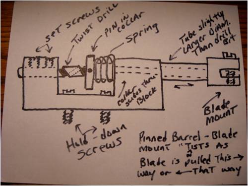
Once again: a twist drill is locked in place in one end using two set screws, held in a hole it drilled, by the way! A collar drilled one size larger than the twist drill slides over the twist drill and through the other end of the block. Whatever diameter you make the collar, just jump up to the next-size drill bit (use a chart and don't guess!) and drill a hole for the collar to rotate within. A set screw or pin is threaded through the thickest portion of the collar and that pin rides inside one flute of the twist drill. The blade is locked into the outboard portion of the collar. As the windmill turns, centrifugal force pulls the collar against the spring, which attempts to keep it inboard. As it pulls either direction, the pin follows the twisted groove (flute) of the drill and the collar-and-blade combination twist that amount. To make it work in a true "feathering" manner, all three blades would have to be synchronized using gears, so each one turned the same amount as any other, otherwise, one blade will have more pitch than the other two, throwing things out of balance. I don't have any need for it to feather, but if I ever do, I'll design a synchronous system and post it here. I need this to default to 45-degrees as I am interested only in torque at this time. Edit: If you are interested in a full-feathering arrangement using this method to actuate it, let me know and I'll work it out. I had the privelege of meeting and talking to "Mr. Jacobs" of Jacobs Wind Electric back in the early 1970's and he allowed me to fiddle with one of his rigs. I paid close attention to his feathering device and I think I can approximate it from memory using the twist-drill as a motion inducer. Just let me know. . . . . Mac Nothing difficult is ever easy! Perhaps better stated in the words of Morgan Freeman, "Where there is no struggle, there is no progress!" Copeville, Texas |
||||
| MacGyver Guru Joined: 12/05/2009 Location: United StatesPosts: 1329 |
[Quote=Oztules]Macgyver..... I can't reply to your question.... your bin is full. Oopsie! I wasn't aware it could fill up. I'll try to be more diligent about deleting messages I've read from now on. Edit: Almost forgot the most important thing: I emptied it! :O) . . . . . Mac Nothing difficult is ever easy! Perhaps better stated in the words of Morgan Freeman, "Where there is no struggle, there is no progress!" Copeville, Texas |
||||
KarlJ Guru Joined: 19/05/2008 Location: AustraliaPosts: 1178 |
Will 5mm plate do it for the backing of the mags? its 1mm short of the 1/4" tules recommends but I have come across some 300mm lasercut rounds in 5mm... what do you reckon tules? Luck favours the well prepared |
||||
| GWatPE Senior Member Joined: 01/09/2006 Location: AustraliaPosts: 2127 |
Hi Karl, the backing plate thickness is related to the strength and thickness and size of the magnets. Ideally, there should be no flux lines coming out through the iron, behind the magnets. Test with only 1 plate, as I have found that when the second plate is in place, that the field is more contained within the iron plates. I use 3/8" plate for 1/2" thick mags. Gordon. become more energy aware |
||||
Downwind Guru Joined: 09/09/2009 Location: AustraliaPosts: 2333 |
I see no reason why you can not stack 2 of the 5mm plates together and get 10mm thickness.(3/8) Might want to put a film of silicon between them to stop water getting in between and clamp them down to dry. Pete. Sometimes it just works |
||||
| oztules Guru Joined: 26/07/2007 Location: AustraliaPosts: 1686 |
Yes Pete that will work, but is probably overkill for MacGyvers magnets.... 5mm would still be fine for his mag size (diameter dependent then). As Gordon remarked, it is just a function of magnet size. If you can stick a paper clip to the back of the plate when the magnets are on, you need a little more steel. If the clip falls off, the fields do not escape the plate.... so enough.... it is not super critical if close. When you start using bigger magnets, you may find you need thicker than actually required ... just for the physical strength to keep the magnets apart on a large radius plate. I bolt the blades directly to the front plate (mounted directly to the front flange of the hub... not hanging on the studs as seems prevalent at fieldlines). I find 8mm is enough for strength at 14" and flux for 50x12mm rounds. Use what you have available, and it will work. Perfection in this area is not as critical as strength. For 12" and more, I think 6mm is thin, 8mm fine 10mm plenty of insurance, and bigger won't blow away in a hurry.... and the blades will not bother it. ......oztules Village idiot...or... just another hack out of his depth |
||||
