| |
  Page 3 of 4 Page 3 of 4   |
| Author |
Message |
Downwind

Guru

Joined: 09/09/2009
Location: AustraliaPosts: 2333 |
| Posted: 03:23am 18 Jun 2010 |
 Copy link to clipboard Copy link to clipboard |
 Print this post |
|
Whats the opamp you are using as the TC271 was not one i could find a data sheet on.
Pete.
Sometimes it just works |
| |
niall1

Senior Member

Joined: 20/11/2008
Location: IrelandPosts: 331 |
| Posted: 09:30am 18 Jun 2010 |
Copy link to clipboard |
Print this post |
|
sorry its a tlc271...(sorry about the typo  ).. the full parts list is in the pdf ).. the full parts list is in the pdf
this it the thread i found the circuit at...
http://www.picbasic.co.uk/forum/showthread.php?t=7179
Edited by niall1 2010-06-19
niall |
| |
Downwind
Guru
Joined: 09/09/2009
Location: AustraliaPosts: 2333 |
| Posted: 12:20pm 18 Jun 2010 |
Copy link to clipboard |
Print this post |
|
Hi Niall,
A little TLC makes a big difference. 
It looks like a very trick op-amp and well suited to your application.
Im not a guru on op-amps as OZ would know more than me here.
Being a single opamp it might be harder to filter noise from the mill or diodes for your application.
From what i see on your board it looks a little light in capacitor value for windmill noise.
As a plan "B" (and only as plan B) should we not be able to get your circuit give you what results you want.
I will send you a test board (size of a postage stamp) with a dedicated chip, i have been testing with good results thus far.
Do you have a cro?
I am interested in your results.
It would be good to have a op-amp alternative design, rather then a dedicated chip, as the chip cost is around $10.00 and tiny to work with.
Pete.
Sometimes it just works |
| |
niall1
Senior Member
Joined: 20/11/2008
Location: IrelandPosts: 331 |
| Posted: 02:28pm 18 Jun 2010 |
Copy link to clipboard |
Print this post |
|
hi Pete
thanks for looking at the chip....i really dont know much about opamps but for me they are easy to deal with or replace , although this one may be sensitive to static...i,ll check before i put one in ..i might be able to do some very basic tests to see any amplification .... they arrived today
i dont have any sensitive measuring equipment...nor know to use the like , things may fall flat on their feet fairly soon.....
if it goes too much beyond plug and play it gets a bit daunting
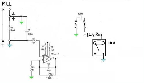
it is interesting about the use off capacitors..that i can do and advise about it is very much appreciated , maybe i can pre-empt a few things here...in the cct the small shunt has a 330n cap across it ...
i have plenty off biggish uF polyester/polyproplyne ones from old pc psu,s ..
should i add one off them instead ? or anywhere else ?
i rembember reading posts on fiedlines about high esr capacitors being good at putting a lid on things when it came to noise
plan B......thats a neat offer on your dedicated chip...it sounds the real deal
erm...so i suppose i,ll stick with plan A ..it,d be fun to see what it does or dosent come up with
(just to recap , its not so much the logging part i,m thinking about yet , although i really like that aspect of it ,but more to do with Gordons earlier comment of power loss in larger shunts at lower voltage ...)
later edit...fun part
some testing on the chip with 2 different 7 euro meters ..( ) ..simple guessed adjustable divider , basic psu....chip is tlc271cp
opamp gain pot r at 36.8k
05mv in .209v out....gain by 41.8
10mv in .398v out.........by 39.8
20mv in .770v out.........by 38.5
30mv in 1.145v out.........by 38.1
40mv in 1.515v out.........by 37.8
50mv in 1.887v out.........by 37.7
gain pot r at 100k
05mv in .56v out..........by 113
10mv in 1.06v out..........by 106
20mv in 2.05v out..........by 102
30mv in 3.06v out..........by 102
40mv in 4.06v out..........by 101.5
50mv in ....gone too close to 5vcc supply to chip...
(i think this is also the v referance the chip does its math on..not good as the psu 5v is probably all over the place)
variables ....everything
fatalities....0
beer.... Edited by niall1 2010-06-20
niall |
| |
Downwind
Guru
Joined: 09/09/2009
Location: AustraliaPosts: 2333 |
| Posted: 04:41am 19 Jun 2010 |
Copy link to clipboard |
Print this post |
|
Hi Niall,
Your results dont look to bad and with the higher gain close to linear results.
From what i see you will need to trim the pot back till you get a reading at 50mv and settle at that (running the highest gain you can for the 5v window you have)
I take it the testing was not done with a windmill and think this is where you might come unstuck as the noise will cause the readings to fluctuate all over the place.
It is going to be hard to see what is going on without a cro.
You could try some filtering on the output of your circuit but this will also slow the response time to load changes, but i dont think that is an over big issue.
Try a 10K resistor in series with the output, with a 10uF capacitor between the output(after the 10K resistor) and ground.
The cap only needs to be small in voltage rating as the max voltage it will see is 5 volts...so a 10-25volt cap will do fine.
Then take your picaxe input off the resistor and capacitor junction.
If the picaxe readings are unstable you might try increasing the cap to 100uF but this will dampen the response time even more.
As for the loss in the shunt only you can decide what you choose to do there to reduce this.
As your results show, you need a rather high gain with the shunt you have to get somewhere near linear output, but then fall outside the 5v window you have to work with. (this was my whole point of debate above)
A better shunt will equal less gain and not as senseitive to noise.
As i said earlier is a matter of matching the shunt to best fit the application needed, but this has caused enough debate thus far, and i will shut up on this and let you decide on what you choose to do here.
Pete.
Sometimes it just works |
| |
AMACK

Senior Member
Joined: 31/05/2009
Location: AustraliaPosts: 184 |
| Posted: 10:28am 19 Jun 2010 |
Copy link to clipboard |
Print this post |
|
Niall1,
I too am working on the piclog. I am doing a test run on a bread board first. I was going to put it onto a PCB but do not have the gear to do it so I might run it on Vero like the charge controller. I would like to know if you have go a lay out that you would be willing to post, it would save me alot of time and picaxe chip..
As I have said in the past the Location I am at is good for wind and I would Like to Know if anyone has started a Topic in regards to exchanging data from the loggers to see out puts and best configurations to use for there and others sites.
Just a thought....
Many Thanks Andrew
*Note to self
1. Make it thick
2.Make it heavy.
3.Make it stronger than it should be.
4. Don't rush the first job as the second job will cost more and take mor |
| |
niall1
Senior Member
Joined: 20/11/2008
Location: IrelandPosts: 331 |
| Posted: 11:41am 19 Jun 2010 |
Copy link to clipboard |
Print this post |
|
hi Andrew
i,m certainly willing to post up the layout of the board ,and anything else ,but i didnt write down the track cut layout......(about 22 and 8 off these were the ic sockets) i,m sure it could be tidied up...(its beginning to lose its looks a bit now )...its a nice cct for vero i think
this was about the mimium size board for me ...a slightly bigger board wouldnt be any harm ....
i did get a little tight with the opto couplers and some off the components do run over each other thats why some off the wires look a little close
its just a kind of squashed version of the breadboard ...lately i,ve forced myself to get in the habit of doing one section at a time and testing the connections..kind off power section first ,then terminals/ finally pop in the chips into the sockets as a last resort ...if that makes sense...
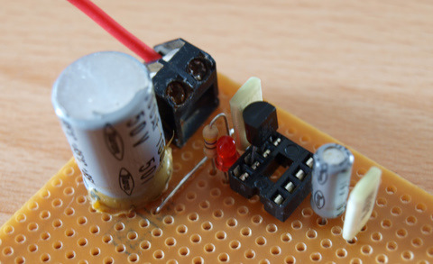
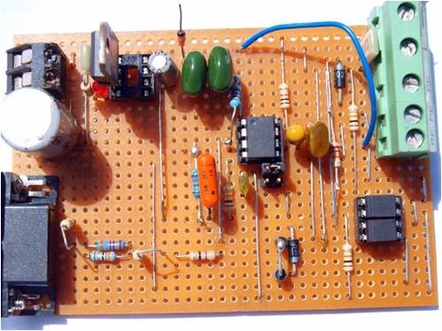
ps...there are one or two extra bits in there ,mainly extra decouplers ...but this was the still the layout off the origional pic circuit..looks like we,re in a similar position ....
i,m still playing with running the voltage and anemometer readings...loggings a long way off yet ..i,m in a good wind area also but its very turbulant which i,d imagine would play havoc with the readings ..Edited by niall1 2010-06-20
niall |
| |
Downwind
Guru
Joined: 09/09/2009
Location: AustraliaPosts: 2333 |
| Posted: 12:17pm 19 Jun 2010 |
Copy link to clipboard |
Print this post |
|
Hi Andrew,
I dont wish to take any thing away from home builds of the piclog circuit design and i am fully supportive of this.
I am about to post a redesign of the logger circuit and offer it as a kit form with pcb and all the parts supplied should this be of interest to your needs.
I have been a bit slack at compiling the information to post in full form, but will in the next few days.
I will give all information for those who wish to copy any sections of the design.
This has run into some negative press with offering this in kit form, but my intensions are to help people like yourself who find difficulties in putting the circuit onto a board.
Pete.
Sometimes it just works |
| |
AMACK
Senior Member
Joined: 31/05/2009
Location: AustraliaPosts: 184 |
| Posted: 12:54pm 19 Jun 2010 |
Copy link to clipboard |
Print this post |
|
Pete,
Thanks for the offer, I will keep looking for it in posts to come. I have seen it in a few post some months back but as you said it went quiet. I have all component for the home brew kit and I like to tinker a bit when I get time.
What price are you thinking of for the kit?? And when will it be about?
You said that you have had, as you say "negative press" on the subject. If you are not trying to get rich on someone's idear and are doing it to help people in the group that do not have the equipment to do so then that fine by me..
There is so much information on this site and alot of members that have so much information to offer to other's and it is hard to keep up. I have been back to the books on so many topics so I can under stand some of the information that is on offer. In breif this is a grate site and any infomation that I get from it is a big help to me.. I have told alot of people about this site and some of them I hope still look over the topics as I do almost every day.  Edited by AMACK 2010-06-20 Edited by AMACK 2010-06-20
*Note to self
1. Make it thick
2.Make it heavy.
3.Make it stronger than it should be.
4. Don't rush the first job as the second job will cost more and take mor |
| |
niall1
Senior Member
Joined: 20/11/2008
Location: IrelandPosts: 331 |
| Posted: 03:33pm 26 Jun 2010 |
Copy link to clipboard |
Print this post |
|
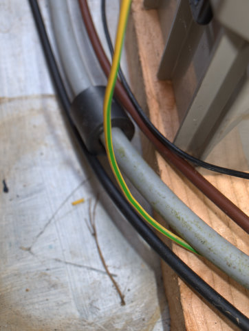
the amp circuit board is kind off finished so i did a basic test with a simple piece off stainless plate shunt to see how it wires up....this stainless is probabely a little long and thick....about half with some fine slots cut in it to bring up the r a little might be just as good...(i dont think its proper stainless either)
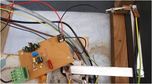
the stainless seems to drop about 60Mv..ish...maybe a little more at close to
full power
not fully sure if this is correct.. ..it seems very odd that the sense v lead ..it seems very odd that the sense v lead
is on the negative battery terminal ?.. but it seems to work ok...its very odd looking at a negative lead and trying to think in terms off positive voltage...
a nice test at this stage was to use a small analogue meter at low voltage to act as an ammeter ,its not calibrated but still works nice and smooth......
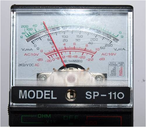
0v.......equals nothing
8v.......the kitchen sink
(it,d seem to be fairly easy to trim the amp o/p to scale the full 10v setting on the meter , just squeeze a little extra gain on the feedback pot)
so far the cct at least ..seems... to work well for something simple like this
a bit more serious calibration when i can borrow a clamp meter and or maybe use the tristars software readings
ps....please excuse the adhoc wiring , i had to change things about a fair bit to try the circuit
Edited by niall1 2010-06-28
niall |
| |
Downwind
Guru
Joined: 09/09/2009
Location: AustraliaPosts: 2333 |
| Posted: 03:35am 27 Jun 2010 |
Copy link to clipboard |
Print this post |
|
Hi Niall,
Have you had the circuit on your mill yet or just bench testing.
The reason i ask is to whether you get much filckering of the meter needle on the mill, as this would be electrical noise coming through.
You might not even notice it with analog meter.
Then there might not be any noise to start with. (Doubt this though)
Watching with interest
Nice work
Pete.
Sometimes it just works |
| |
oztules

Guru
Joined: 26/07/2007
Location: AustraliaPosts: 1686 |
| Posted: 06:25am 27 Jun 2010 |
Copy link to clipboard |
Print this post |
|
Niall
2 simple rules I follow when using whatever as a shunt.
1. Never use the same termination point as the current input or output as the point where you take off the voltage drop to read.
This means, if you use a strip of copper, or s/steel with calibration cuts, then thats fine, but connect current source and current drain to either end of it with their dedicated terminals. (copper is nice as you can solder the sense wires to it when you have your rough calibration in hand)
2. Never have a connection in series in the shunt. It may introduce noise or worse, open circuit and drive the voltage through your sense leads.
ie. use your shunt as a single piece of resistance material and terminate your source and load to it (either end)
THEN, using separate but not necessarily at the same place, but beside etc, terminate your sense leads using dedicated terminations.
One can be soldered etc beside your "earth" power termination, and the other can be shifted along the shunt to find the appropriate mv/amp setting, and affixed/soldered there. That way, both sense wires are effectively shorted by the shunt, independent of any "loose " terminals in the main current loop. (How I would roughly calibrate a shunt, and tidy up with your amp settings))
Just how I'd try it.
It is still not bullet proof, as you may loose the earth terminal somehow, but I haven't seen this fail before either.
Because your impedance is high, maybe some resistors and zeners could allay paranoia.
CT's stop all that too.
...............oztulesEdited by oztules 2010-06-28
Village idiot...or... just another hack out of his depth |
| |
niall1
Senior Member
Joined: 20/11/2008
Location: IrelandPosts: 331 |
| Posted: 11:16am 27 Jun 2010 |
Copy link to clipboard |
Print this post |
|
Pete the circuit was tried on the mill for this test....the battery bank isnt very big
and was close to a fully charged state....so the current indications on the analog
meter were mainly 90% of mill (batt) power being diverted into a heater by the charge controller....some peaks to about 700w
even when full the batts seems to absorb a little power just before the controller kicks in...i could just about see this slight current in the the needle as well
for what its worth i couldnt see any flicker or nervousness in the needle movements...
but i expect the fuzz is in there somewhere waiting to come out
one thing i forgot to mention before...i did put a big ferrite bead on the mill cables
it was just lying around and was a neat fit...have no idea if it helps
i think i can understand your pointers Oz and will try to follow them ...so i,ll make another neater shunt and lock down the wiring ..i have a rough idea now what size it might need to beEdited by niall1 2010-06-28
niall |
| |
niall1
Senior Member
Joined: 20/11/2008
Location: IrelandPosts: 331 |
| Posted: 02:48pm 30 Jun 2010 |
Copy link to clipboard |
Print this post |
|
i,ve tried to tidy up the shunt a bit and set the o/p to about 4v max with the pre amp..the sense wires are soldered on to the shunt on the other side off their mounting holes
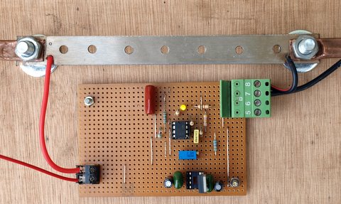
hope this is along the lines off your suggestions Oz...the pic was ready for a go now
but as it seems to have a time delay on the readings i aimnt sure whats the best way to try to calibrate the them
i decided to run the pic alongside the software for the C60 dump controller and try to do a ball park check on the readings...the pic below shows both amp readings pretty close ....they wernt all as good as this and impossible to sync as its hard to start two programs with one mouse...the tristar almost reads in realtime so a lot off readings pop up
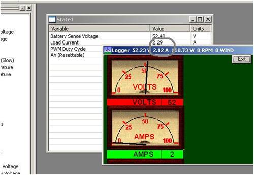
this is fun .....but tricky as you go a bit cross eyed doing it
after a bit of tweaking the pic settings i tried a few simple short logs ...
one on the pic...with an almost a simultaneous one on the C60
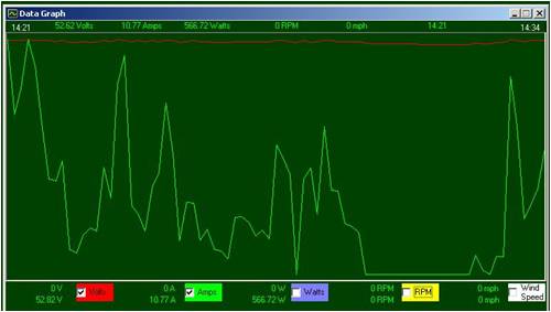
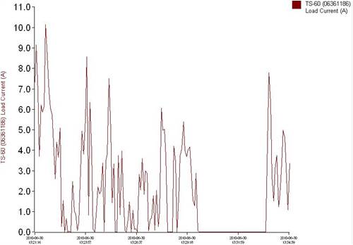
this isnt a level playing field though...the C60 logs only dumped power
the pic is trying to log dumped and trickle charge the the batts...but both graphs seem to show a kind off similarity......
its good fun but i need to tidy up everything before i set fire to the desk
Edited by niall1 2010-07-02
niall |
| |
Downwind
Guru
Joined: 09/09/2009
Location: AustraliaPosts: 2333 |
| Posted: 03:34pm 30 Jun 2010 |
Copy link to clipboard |
Print this post |
|
Hi Nial,
Good to see you have progress and are getting reasonable results.
The time delay could be because you have piclog set to 10 second reads or greater.
This is where it needs to be for logging but with setup it could be worth reducing the logging interval to every 1 second to reduce the time delay.
It could also be in your picaxe program causing a long delay between data strings, if you want to zip the program and post it i can have a look through it if you like.
The other thing with reading a shunt like this it wont give a real linear reading down low like where you are, as well as read up into the high amp range.
You will find it will work much better as the amps come up higher.
Pete.
Sometimes it just works |
| |
niall1
Senior Member
Joined: 20/11/2008
Location: IrelandPosts: 331 |
| Posted: 04:04pm 30 Jun 2010 |
Copy link to clipboard |
Print this post |
|
hi Pete
there is another reference unit which i can maybe use ...i think
the tristar can monitor total amp hours ...down to .1A
the pic watt hours....
in a 48v system ..is 1 amp hour equal to a 48watt hour reading the pic ?...
this seems to add up...i understand your point about the shunt , a compromise in readings would be ok with me
Edited by niall1 2010-07-02
niall |
| |
Downwind
Guru
Joined: 09/09/2009
Location: AustraliaPosts: 2333 |
| Posted: 04:48pm 30 Jun 2010 |
Copy link to clipboard |
Print this post |
|
Hi Niall,
Yes just drop the Hours off and its back to ohms law.
48v x 1A = 48W
I think you are trying to do this the hard way.
First you need to set the offset in piclog calibration, with no amps going through the shunt (maybe with shunt disconnected from mill and battery) press the amps zero button.
Do you have a amp meter of some sort..analog or on your multimeter.
If so then disconnect the load side of the shunt and put the meter in series with a fixed load like a light globe or large resistor.. anything to give a constant load that is within the range of your meter.
This way you should have a steady reading off the battery. (you might need to swap the sense wires aroung off the shunt as it will be working backwards off the battery)
Read the amps on the meter.
Now calibrate piclog to this reading.
To do this take the picaxe raw data reading showing in the calibration window and divide it by your meter reading, this will give you the value you need to enter into piclog for a calibration factor.
Ok job done its calibrated, and reconnect the shunt as it was and start logging.
Pete.
Sometimes it just works |
| |
oztules
Guru
Joined: 26/07/2007
Location: AustraliaPosts: 1686 |
| Posted: 10:27pm 30 Jun 2010 |
Copy link to clipboard |
Print this post |
|
Nice work Niall
Nice shunt there, should work well.
Pete has said it all I think.... stop trying to calibrate on the run,as you will lose whatever hair you have left. Static calibration is the only hope you have to remain sane.
...........oztules
I do like the analogue meters too.
Village idiot...or... just another hack out of his depth |
| |
niall1
Senior Member
Joined: 20/11/2008
Location: IrelandPosts: 331 |
| Posted: 03:34pm 17 Jul 2010 |
Copy link to clipboard |
Print this post |
|
i tried out a fairly simple static calibration using some 10r 300w power resistors ..this made the amp calculations fairly easy and ..seems.. ok for me
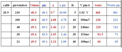
as far as i can see at low power readings there is a certain amount off error using the simple shunt but this error improves a lot as the power goes up so i think i,m happy enough with the shunt...the pre amp gain is set at 30 and at close to 500w the shunt drops about 30Mv ..
i think this works out at about .3w ? power loss in the shunt at close to 500w
niall |
| |
Downwind
Guru
Joined: 09/09/2009
Location: AustraliaPosts: 2333 |
| Posted: 04:27pm 17 Jul 2010 |
Copy link to clipboard |
Print this post |
|
Hi Niall,
Good to see you have some working results.
Your recordings reflect a non linear result and will be out each side of calibration point.
It is what i was commenting on previous with making a shunt, as its easy to construct one, but hard to get linear across a given scale (Oz will bite me about now  ). ).
In many cases if you log a constant power load for some time you will also see a further drift due to temperture in the shunt.
The difference in results could be in your circuit but i suspect it to be the shunt.
Pete.
Sometimes it just works |
| |
| |
Page 3 of 4 |
