| |
  Page 3 of 4 Page 3 of 4   |
| Author |
Message |
Shelly
Newbie

Joined: 22/12/2009
Location: SpainPosts: 25 |
| Posted: 04:32pm 07 Jul 2010 |
 Copy link to clipboard Copy link to clipboard |
 Print this post |
|
Hi Bob,
Wiped the photos off by mistake  Tomorrow. I've adjusted as you said, but the moment I reduce the voltage without touching anything else the relay switches out. When the photos are posted perhaps you'll be able to see something I've missed. Tomorrow. I've adjusted as you said, but the moment I reduce the voltage without touching anything else the relay switches out. When the photos are posted perhaps you'll be able to see something I've missed.
Thanks |
| |
Downwind

Guru

Joined: 09/09/2009
Location: AustraliaPosts: 2333 |
| Posted: 04:50pm 07 Jul 2010 |
Copy link to clipboard |
Print this post |
|
Shelly,
What resistor have you for R1 as there is a few changes that has been made and you will need 10K in there and not 12K as some diagrams show.
There is also a second 12K resistor off the 8 volt rail to both trimpots in some diagrams to, that should also be 10K as well.
I was unable to get one i built to adjust either till i changed these resistors.
Worth a try.
Pete.
Sometimes it just works |
| |
Shelly
Newbie
Joined: 22/12/2009
Location: SpainPosts: 25 |
| Posted: 08:27pm 07 Jul 2010 |
Copy link to clipboard |
Print this post |
|
Hi Pete,
I'll have a look tomorrow and if necessary change them. Just been watching Spain win  
Thanks |
| |
Shelly
Newbie
Joined: 22/12/2009
Location: SpainPosts: 25 |
| Posted: 07:55pm 10 Jul 2010 |
Copy link to clipboard |
Print this post |
|


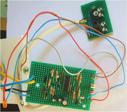
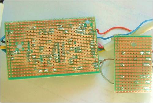
Here are the photos at last.
I have changed the resistors as suggested but no difference. The relay still trips out when the voltage is changed not when the low volt pot is altered. I have reached my limit of knowledge. Is there anyone prepared to make me one? I will obviously pay costs, postage etc. It is now becoming quite urgent. Help would be greatly appreciated.
Thanks for all the advice. |
| |
Shelly
Newbie
Joined: 22/12/2009
Location: SpainPosts: 25 |
| Posted: 07:59pm 10 Jul 2010 |
Copy link to clipboard |
Print this post |
|
Here they are, I think!!
|
| |
Downwind
Guru
Joined: 09/09/2009
Location: AustraliaPosts: 2333 |
| Posted: 08:02pm 10 Jul 2010 |
Copy link to clipboard |
Print this post |
|
I would make you one but the postage cost would kill it.
Lets see if someone else is closer to you.
I would rather help you fix the one you have, as we have been down this road before and everone has got it to work and you will to.
Dont give up.
Pete.
Sometimes it just works |
| |
Downwind
Guru
Joined: 09/09/2009
Location: AustraliaPosts: 2333 |
| Posted: 08:07pm 10 Jul 2010 |
Copy link to clipboard |
Print this post |
|
I cant see what the purple and pink wire is connected to from the trimpots on the main board.
Looks like you have cut the track but not connected any thing to them.
Pete.Edited by Downwind 2010-07-12
Sometimes it just works |
| |
Shelly
Newbie
Joined: 22/12/2009
Location: SpainPosts: 25 |
| Posted: 08:17pm 10 Jul 2010 |
Copy link to clipboard |
Print this post |
|
The 2 outside wires are from the outside terminals of the pots. They were soldered on before I realised they weren't needed. I presume the pots are OK. I miss ordered. In this part of the world I have to buy from Britain or America. There are places here but it is still cheaper to buy from abroad. The only other thing I can think of is that the op-amp was shorted and is soldered directly to the board. Could this have been damaged? The large yellow and blue wires go to the relay, the finer blue and black are the power.
As far as manufacture, all I need is the board. I have a box for it.
Thanks
Shelly aka Brian |
| |
Downwind
Guru
Joined: 09/09/2009
Location: AustraliaPosts: 2333 |
| Posted: 08:24pm 10 Jul 2010 |
Copy link to clipboard |
Print this post |
|
What value are the pots? are they 10K ??
It might pay to take another set of voltage readings at the pins again as this is all we have to track down the fault.
Pete
Sometimes it just works |
| |
Downwind
Guru
Joined: 09/09/2009
Location: AustraliaPosts: 2333 |
| Posted: 08:43pm 10 Jul 2010 |
Copy link to clipboard |
Print this post |
|
Working through the pin voltages you posted last i am troubled with pin1 as the voltage dont change so you might have a solder brige on pin 1 or a damaged chip.
Retest the voltage on pin 1 as you adjust the voltage it should switch from about 1.5 volt to about 7 volts........there is a problem there.
pete.
Sometimes it just works |
| |
Downwind
Guru
Joined: 09/09/2009
Location: AustraliaPosts: 2333 |
| Posted: 08:56pm 10 Jul 2010 |
Copy link to clipboard |
Print this post |
|
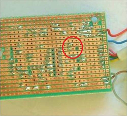
I think you might find a copper bur next to the jumper off pin1 where you cut the track.
Your problem lies around pin 1 look very carefully you will find a bridge or short there some where.
Look Here
Pete.Edited by Downwind 2010-07-12
Sometimes it just works |
| |
Downwind
Guru
Joined: 09/09/2009
Location: AustraliaPosts: 2333 |
| Posted: 09:05pm 10 Jul 2010 |
Copy link to clipboard |
Print this post |
|
I must be off i will check back later.
Good luck.
Pete.
Sometimes it just works |
| |
Shelly
Newbie
Joined: 22/12/2009
Location: SpainPosts: 25 |
| Posted: 09:23pm 10 Jul 2010 |
Copy link to clipboard |
Print this post |
|
OK one by one!!
The pots are 10k and will switch the power on and off so I presume they are Ok
There are no solder bridges anywhere. I have scored between the strips with both a steel dental pick and a broken hacksaw blade and finally brushed it down with an old toothbrush.
I think the op-amp is damaged and will replace it and use a "plug" this time so it's not soldered.
As can be gathered, electronics is not my hobby, model railways is. The circuit diagram for the desulfator is Ok? If it is I'd like to make one to see how effective it is and I can order all the bits in one go to save on postage. I'm also looking for a circuit or kit or ready made to switch a 230v ac on and off. It's for a small pump of 40 watts that circulates water around a couple of small ponds. I want to prevent the ponds being pumped dry in case there is a leak. Not renewable energy but I'm sure a use could be found for something like this, for example protecting a water heating system.
Again, thanks for your help and time
Brian
PS Wave a flag for Spain tomorrow!!  |
| |
Bub73

Senior Member

Joined: 10/12/2009
Location: United StatesPosts: 116 |
| Posted: 02:01am 11 Jul 2010 |
Copy link to clipboard |
Print this post |
|
I see what looks like the same copper bur next to the jumper off pin1 that Pete dose.
Also I like the idea of using a socket for the op amp; it helps to keep heat and static of the chip during assembly as well as easy replace should the magic smoke get out. Install the chip last.
Bob |
| |
Shelly
Newbie
Joined: 22/12/2009
Location: SpainPosts: 25 |
| Posted: 08:25pm 12 Jul 2010 |
Copy link to clipboard |
Print this post |
|
Thanks for all the help. Since the photos were taken I have cleaned the track several times. I am sure there are no bridges. When I have an order worth sending I'll get a new op amp plus socket. Whilst this is not a hobby I do find it interesting if not a little frustrating! |
| |
Downwind
Guru
Joined: 09/09/2009
Location: AustraliaPosts: 2333 |
| Posted: 05:39am 13 Jul 2010 |
Copy link to clipboard |
Print this post |
|
Its worth using Murphys law here and get two chips and you will never need the second one.
If you had a ic socket on your board, i would have said to remove the chip and test the voltage to pin one, as you would have seen real quick is there was a short or the chip was the problem.
Rule number 1.............ALWAYS use a ic socket as the cost is small for the benifits gained.
Good luck when you get a new chip and remember to come back and tell us the result as we do often wonder if you guys acheive working results.
Pete.
Sometimes it just works |
| |
readyakira

Senior Member
Joined: 17/07/2008
Location: United StatesPosts: 114 |
| Posted: 04:18pm 22 Jul 2010 |
Copy link to clipboard |
Print this post |
|
for your pump circuit I have a circuit somewhere that could be adapted if you have a low voltage power source. You would have to use a relay for the 230v part, lemme see if I can dig up a link to the guy that designed it.
Don't you think Free/Renewable energy should be mandatory in new buildings? |
| |
readyakira
Senior Member
Joined: 17/07/2008
Location: United StatesPosts: 114 |
| Posted: 04:22pm 22 Jul 2010 |
Copy link to clipboard |
Print this post |
|
this is the website of the guy that designed the circuit. I am having a hard time finding it though. maybe I can re-draw it from the circuit I made...
Don't you think Free/Renewable energy should be mandatory in new buildings? |
| |
Downwind
Guru
Joined: 09/09/2009
Location: AustraliaPosts: 2333 |
| Posted: 04:59pm 22 Jul 2010 |
Copy link to clipboard |
Print this post |
|
Have i missed something here?? What/who pump circuit are you reffering to.
Pete.
Sometimes it just works |
| |
readyakira
Senior Member
Joined: 17/07/2008
Location: United StatesPosts: 114 |
| Posted: 11:19am 23 Jul 2010 |
Copy link to clipboard |
Print this post |
|
shelly talked about a circuit to toggle a 230v pump. I had a 12v circuit that I used to monitor water level in my hydrogen cell when I was playing with those. I would turn on a windshield washer pump to add more electrolyte when the level fell below the two screws used to make a connection thru the water. I am sure it could drive a relay for that pump.
Don't you think Free/Renewable energy should be mandatory in new buildings? |
| |
| |
Page 3 of 4 |
