
|
|
Forum Index : Microcontroller and PC projects : Growing a Maximite
| Author | Message | ||||
Grogster Admin Group Joined: 31/12/2012 Location: New ZealandPosts: 9084 |
@ paceman - I think the cap HAS to use X5R does it not? Perhaps I have that wrong... @ robert.rozee - good points there. Especially about the thermal releif on GP connections - exactly as I do my own boards, and for the same reason. I have had a few RF boards(not my designs) where there was no thermal relief, and they were MUCH more of a pain to solder, as the large GP sucks all the heat away from the iron. Copper is a good conductor of heat, don't forget!  Smoke makes things work. When the smoke gets out, it stops! |
||||
bigmik Guru Joined: 20/06/2011 Location: AustraliaPosts: 2870 |
Hi Tz, An interesting PCB, Actually near beautiful.. One constructive criticism is that the Pad holes that are GND are fully connected to the GND plane (Polygon fill) and that might make it difficult to get enough heat into those pins to solder easilly. See the Right hand Pair of these pads , below, to see what I mean.. They are connected to the Polygon GND fill but only by small traces (usally 4 , top, bottom, left and right) to the large GND fill. This allows the pins to be soldered without a lot of heat being applied. 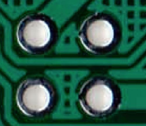
Regards, Mick EDIT*** Actually not a great photo but was a quick scan... If you like I will cut and paste from Protel to show what I mean. Regards, Mick Mick's uMite Stuff can be found >>> HERE (Kindly hosted by Dontronics) <<< |
||||
| MicroBlocks Guru Joined: 12/05/2012 Location: ThailandPosts: 2209 |
@robert Thanks for the feedback. I fixed the 0.1" grid. I had to move one connector to have more space for traces but i found another way to route it (all manual as autoroute does not give good results). The footprint for the caps close to the regulator are on 1206, for smd that is already rather big. :) For C1, i routed the board with a 0603 as that as the size for a X5R, making it bigger will require major rerouting and searching the web i found a few alternative brands with the same 0603 footprint. The copper pour is now with thermals. Have to clean up some manual routed traces that interfere with that. @robert and @mik. When you use reflow would large copper contact not be better, like when used on a hot plate? Or is the 4 spokes a good compromise for smd parts. For through hole i have experienced the advantage of thermals. :) Microblocks. Build with logic. |
||||
CircuitGizmos Guru Joined: 08/09/2011 Location: United StatesPosts: 1421 |
That is only slightly more board area than the CGMMSTICK, and you placed a 100 pin chip instead of the smaller 64-pin. Good job! 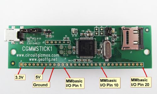
Micromites and Maximites! - Beginning Maximite |
||||
| MicroBlocks Guru Joined: 12/05/2012 Location: ThailandPosts: 2209 |
I moved the supervisory chip to another place and that will allow an even smaller versions of the board. Everything is on 0.1" grid. The cut of line will be right next to the connectors, cutting of the micro usb and icsp. It will then be 50x40. :) Good if space is a premium. Still allows usb and icsp connection through the existing connectors. I have dropped the diode that protects if you have usb and external power at the same time and replaced it with a header so that a choice can be made to use diodes or a switch. Microblocks. Build with logic. |
||||
| MicroBlocks Guru Joined: 12/05/2012 Location: ThailandPosts: 2209 |
Few hours later, eyes half closed. :) Moved some parts around, made a cutoff area if you don't want USB and ICSP on the board and added a mini 'sea of holes' or maybe better named a 'lake of holes'. Added headers to breakout the USB pins. Color coded the pins in use by maximite. ( Light green/dark green center = 3.3v light green/greyblue center = 5v blue/blue center = vss White = PIN1-20 Darkred = Arduino pins Grey = SD card Yellow/Red/Green/Blue = VGA, Black/Red center = reset 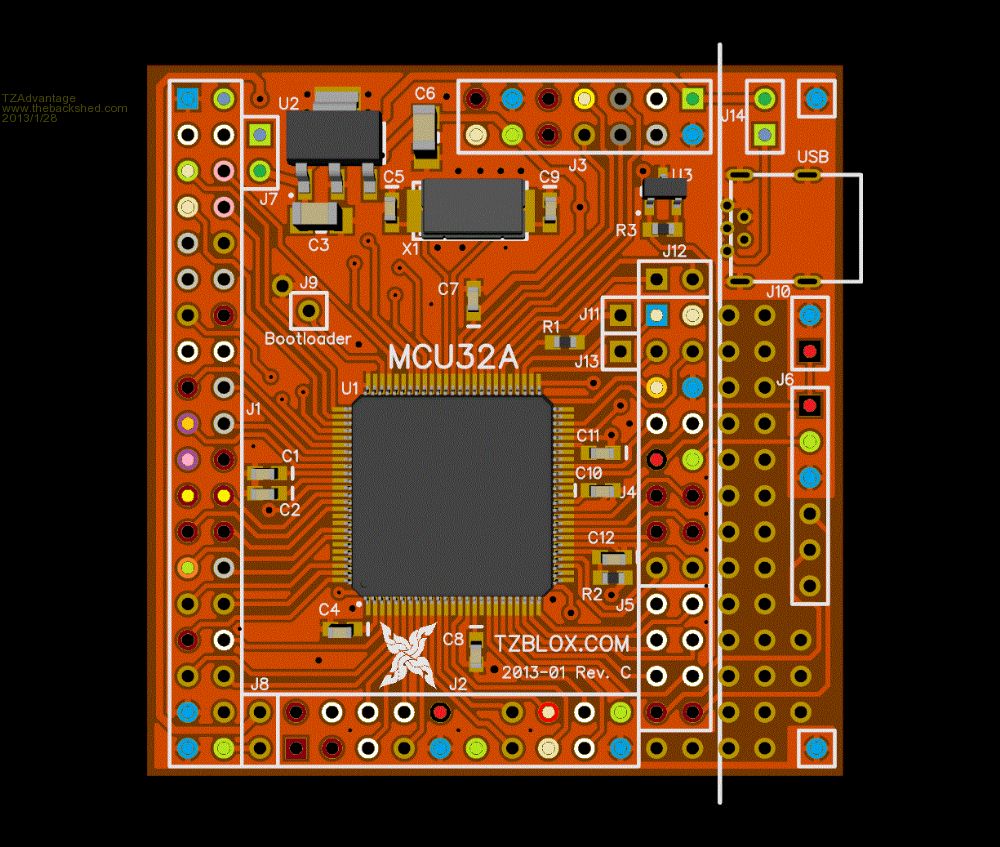
Microblocks. Build with logic. |
||||
| Grogster Admin Group Joined: 31/12/2012 Location: New ZealandPosts: 9084 |
Very impressive. 
[quote]Few hours later, eyes half closed. :)[/quote] Yeah, I know what you mean. Sometimes when designing boards, I find myself at all crazy hours of the morning, slumped over the computer when I should be in bed asleep!!!  Smoke makes things work. When the smoke gets out, it stops! |
||||
| bigmik Guru Joined: 20/06/2011 Location: AustraliaPosts: 2870 |
Hi TZ, I am no expert on Reflow solder.. (In fact I am not an expert on much these days) but you did say that it was for Proto and Production.. I was commenting on it from a hand soldered perspective.. I like it!! It is like a breath of fresh air.. I have mentioned several times before that I love the idea of a MMStamp.. This would fit the bill perfectly.. Regards, Mick. Mick's uMite Stuff can be found >>> HERE (Kindly hosted by Dontronics) <<< |
||||
| Grogster Admin Group Joined: 31/12/2012 Location: New ZealandPosts: 9084 |
YES - I totally agree. I was going to design something along the same lines as TZA has come up with myself, but as he has now done it... 
I know that CircuitGizmos have the same kind of thing for the 64-pin B/W MM, but I wanted a colour-compatible one. Now, the question is - how long till TZA gets the prototypes made and tested, then we can buy them if the prototype works OK... Smoke makes things work. When the smoke gets out, it stops! |
||||
| MOBI Guru Joined: 02/12/2012 Location: AustraliaPosts: 819 |
When I started this thread, I imagined a simple breakout board done on single sided PCB that "anyone" could put together in their own back shed i.e PCB etching and soldering using (except for the PIC32) "normal" through hole components. The idea being that the experimenter could make up his/her own I/O modules also on SS PCB. I note that the original maximite used many through hole components. I think I will still persue that project. Are there crazy people out there like me who get a kick out of building? I like to say, when it is all done and working "well, I beat you, you ....." Mind you, I do like the TZA version. David M. |
||||
| Grogster Admin Group Joined: 31/12/2012 Location: New ZealandPosts: 9084 |
Yes, my original idea was to mount the PIC32 on a single-sided board, and all through-hole parts with the exception of the 10uF ceramic. The board would be much bigger being single-sided, but it would be do-able. I'm still toying with that idea, but with others designing things I was thinking of doing myself, there does not seem like a lot of point in my reinventing the wheel.
I might still look at this. Gemerally speaking, double-sided boards cost twice as much as the same size single-sided, so although building a SS MM clone would mean a proportionally bigger PCB, board size has never really been any concern of mine for the most part - it kinda depends on exactly where you are planning on putting something. Normally, I can happily work with larger SS boards, but to be honest, I am starting to play with DS boards now. Still, 99% of my boards are SS all the same. Smoke makes things work. When the smoke gets out, it stops! |
||||
| bigmik Guru Joined: 20/06/2011 Location: AustraliaPosts: 2870 |
They `should' be, as they dont need the plating process but I have found that the price is the same to get them made, certainly from the cheap Chinese manufacturers. (I suspect they do the same processes and just etch the other side away. The real problem I have with SS is that the tracks can peel away a lot easier if too much heat is applied, DS dont have the same problem as the VIAs and PADs give more stability and strength to the track. Regards, Mick Mick's uMite Stuff can be found >>> HERE (Kindly hosted by Dontronics) <<< |
||||
| MOBI Guru Joined: 02/12/2012 Location: AustraliaPosts: 819 |
[QUOTEmick]The real problem I have with SS is that the tracks can peel away a lot easier if too much heat is applied I have really only had that problem using the phenolic boards but also I use a good temp controlled iron with a fine tip. It also helps to HALS tin the board first using tin paste and a heat gun (or gas flame if you are quick). My aim was to have the PIC32 and power supply on a single header board with the caps particularly the 1.8v core regulator one. It was intended more as a BASIC programmable MCU than a computer with I/O interfaces separately as the application needed. Software changeable via the SD card and autorun file. David M. |
||||
| MicroBlocks Guru Joined: 12/05/2012 Location: ThailandPosts: 2209 |
Believe it or not , but the board i designed started out as single side. I found out however that putting in the decoupling caps and the crystal made it impossible. The crystal has its own caps, ground planes and similar length traces to minimize the influence to and from other traces/parts. The traces would be too long and the size of the board would at least be double when using single side. I then made the decision to make it a double sider and put on all the parts that are absolutely necessary for a working PIC32. Then put on the headers to get everything on a 0.1" grid for through hole use. Having space available i put in the 3.3v regulator, supervisory, USB and iscp. Designing some i/o now is very easy and can be done on a vero board or single side home made boards. The arrangement of the headers is not with an Maximite in mind. They are grouped according tothe peripherals in the PIC32. Especially I2C,SPI,Serial Port A,B and E, CAN and a 16 bit PMP port suitable to control a LCD or large amounts of IO like LED arrays. MM uses very few of these as VGA uses most of the SPI/Serial/I2C peripherals and uses bitbanging to compensate for it. Others who would like to program in Assembler or C would rather use the peripherals directly and this board allows that as every pin can be used as you wish. As such it is for me a direct replacement of the UBW32 which is a nice board but the shape is too long for all of my final products that i have in mind to make. That shape is perfect to put it in a breadboard, but my board using female headers would be sitting next to a breadboard and offer the same ease of use. In short my feeling is that single side can be done, but in the end it is not as reliable as a double sided and i doubt it will be cheaper. Microblocks. Build with logic. |
||||
| paceman Guru Joined: 07/10/2011 Location: AustraliaPosts: 1329 |
Not sure about that Grogster but it seems to be more that X75 is more temperature stable wrt capacitance. Whether that affects ESR I don't know. Here's some Wikipedia info: X5R performs better than other dielectrics, such as Y5V, and permits the construction of physically smaller capacitors than other dielectrics, such as NP0 and X7R. Typically its temperature variation of capacitance is +/-15% over a range of -55 to +85 degrees Celsius. The temperature variation is, however, non-linear.[3] X7R is designed for capacitors with capacity ranging typically between 3.3 nF to 330 nF (SMT: 100 pF to 10 �F). Good for non-critical coupling, filtering, transient voltage suppression, and timing applications. Has high dielectric constant. It is an EIA Class 2 dielectric. Its variation over a temperature range of −55 to +125 �C is �15%. I downloaded the Murata Tech stuff on those caps but it's 273 pages! From what I can gather on the first few pages the GRM series caps are general purpose, whereas they do have another series that are recommended for low ESR. I think I'll just have to give them a go and see - unless someone else can enlighten us. Greg |
||||
| Grogster Admin Group Joined: 31/12/2012 Location: New ZealandPosts: 9084 |
@ paceman - okey dokey - sounds like good info. Let us all know what happens. Smoke makes things work. When the smoke gets out, it stops! |
||||
| JohnS Guru Joined: 18/11/2011 Location: United KingdomPosts: 3678 |
A couple of LEDs plus a Reset and User button are rather useful if there's room or is the plan they'd go on the board this would mount on? John |
||||
| MicroBlocks Guru Joined: 12/05/2012 Location: ThailandPosts: 2209 |
John, LED's use relatively a lot of power, i would like to leave them out. Also using some ports and dedicate them to a LED would mean that without an extra set of jumpers those pins would not be available or hamper other uses. I am also not a fan of buttons and other switches directly on a pcb. I am not sure if i am the only one that thinks like that. After using the UBW32 i found that LEDS and buttons are more of a nuisance. Normally i mount everything on a front panel so that there is never pressure on the board itself. Also making water tight enclosures would make reset and user buttons on the pcb difficult to reach. BTW, they are easily added on the 'lake of islands' The headers for J4 and J5 are right next to those islands, they have the maximite PIN 1-8 and 3.3v, gnd and reset available. Maybe a test 'plug' with some buttons and leds would be useful, especially to test basic functionality and see if it is actually working. :) I also have to stay diligent into making this board capable of being used as a prototype base and as a final product or part of product. I will soon finalize this board, any advice, additions, requests are more then welcome. Microblocks. Build with logic. |
||||
| isochronic Guru Joined: 21/01/2012 Location: AustraliaPosts: 689 |
Microchip recommend a low ESR (<1 ohm) cap in the "getting started" section of the dspic and pic32 manuals. The important factor is low ESR at high frequencies (say 7 - 10 MHz). There are charts (a fair way through the Murata info) of the ESR vs frequency for the various GRM ranges, the GRM series works OK, I looked at the special Low ESR range but from memory it was higher values intended more for specialized power supplies, pretty expensive too. The Microchip boards use a small GRM series, I have used a larger series GRM31xx which has good specs, works fine and is low cost. [ GRM31CR71A106KA01L ] I bought them from a mob called X-ON based in Perth who stock them, they also stock mini-B through-hole sockets. I used the larger size so I could see the bloody things 
BTW For a development board I think an auxiliary/bypass comms (non-USB)would be useful. The USB based comms can be tricky. |
||||
| paceman Guru Joined: 07/10/2011 Location: AustraliaPosts: 1329 |
That sounds hopeful for mine Stuart. I got mine from Rockby here in Melbourne, 24 cents each I think, minimum qty 10, postage $8 along with a dozen or so other bits. Rockby Item No 39885 . They're Murata GRM31CR71C106KAC7L's in a 1206 package. Greg |
||||
