
|
|
Forum Index : Microcontroller and PC projects : Growing a Maximite
| Author | Message | ||||
| MOBI Guru Joined: 02/12/2012 Location: AustraliaPosts: 819 |
The Microchip manual for the PIC32 electrical specs states Cefc must be 1uF to 10Uf with 10uF being typical. I wonder, has any one tried a lower value than 10uF? I have some smd 1uF caps but not sure if they are low ESR. They are not polarised and I have no way of measuring ESR, only capacitance. Does anyone know an easy way to measure ESR without buying/making an ESR tester? David M. |
||||
TassyJim Guru Joined: 07/08/2011 Location: AustraliaPosts: 5917 |
All this talk about old computers sent me to the shed where I unearthed an Atari Portfolio. The Portfolio has been described as the first handheld PC. Unfortunately (or fortunately in this case), mine has stopped working so I can give it a face lift. There is room inside for a UBW32 or maybe one of the boards being discussed here. The keyboard is a simple 8 X 8 matrix so I am thinking of a picaxe to read the keyboard and emulate a PS2 keyboard or serial. I could also use the Maximite to do it all. The display uses proprietary software and rather than trying to work it out (most likely not achievable), I am going to fit a 20 X 4 line LCD. 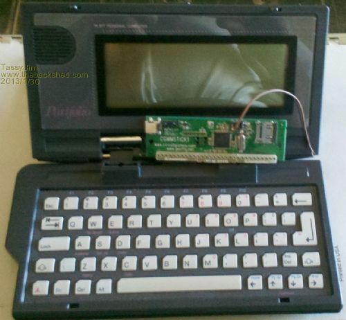
The photo shows the PC with a CGMMSTICK1 sitting on top. Jim VK7JH MMedit MMBasic Help |
||||
| MOBI Guru Joined: 02/12/2012 Location: AustraliaPosts: 819 |
I did a google search and found Geoff's project site which describes measuning Capacitor ESR using a funtion generator, a resistor and a CRO to display the wave forms which can be measured and ESR determined from a simple calculation. That is OK for us who have a CRO. No function Generator, but a PIC could substitute. I checked on ebay and there are lots of ESR measurers for around $25 that looke like an LCD with an MCU of some sort. It shouldn't be too difficult to concoct a circuit?? Perhaps easier to buy one but not as much fun? David M. |
||||
| MOBI Guru Joined: 02/12/2012 Location: AustraliaPosts: 819 |
How are you going to provide the Functions keys that e.g. "edit" need for copy/paste etc? Perhaps use ctrl+key? or similar. David M. |
||||
James_From_Canb Senior Member Joined: 19/06/2011 Location: AustraliaPosts: 265 |
Aaah! It's good to see that there are other people who collect such precious old equipment. I also have an Atari Portfolio. I could never get mine to interface with an ATM machine like the one used in Terminator 2. Maybe once you get the MM running in the Portfolio case you could give it a try 
My favourite is a Sharp PC3100 which came with a bigger screen and a serial and parallel cable. If I didn't have a Maximite, I'd consider using it as a controller. Unfortunately, it's very hard on batteries. The HP handhelds (of which I have quite a few) were much more economical. By the way, if you have any old 16MB and 32MB (that's MB, not GB!) compact flash cards, don't throw them away. They're still useful for the DOS based handhelds that have PCMCIA slots. A PCMCIA converter will allow CF cards to be seen as hard drives. Here's a photo of my powered-up Atari. It makes you appreciate the difference in screen sizes these days :) 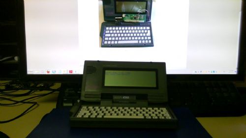
My mind is aglow with whirling, transient nodes of thought careening through a cosmic vapor of invention. Hedley Lamarr, Blazing Saddles (1974) |
||||
Grogster Admin Group Joined: 31/12/2012 Location: New ZealandPosts: 9072 |
"C'mon baby, c'mon baby - Yes! Easy money." - perhaps not that easy. Not sure that this is even possible, despite how cool it looks in the movie. I say this simply because any ATM in the world will only allow ONE PIN number entry attempt per card swipe, so force-feeding the ATM a bunch of codes won't work. Looks good in the movie though! 
No CF cards, but I have plenty of 16MB SD cards. Also have stocks of 64MB uSD(standard SD with adaptor) and 128MB SD cards - ideal for use with the MM. All have been tested with the MM and they all work, which is nice - some FAT filesystem modules for use with controllers don't like the taste of the low capacity cards, and you simply can't use them. Smoke makes things work. When the smoke gets out, it stops! |
||||
| robert.rozee Guru Joined: 31/12/2012 Location: New ZealandPosts: 2292 |
the display uses an 8-bit wide interface, and contains a standard HD44780 style controller that works just the same as the cheap 16x2 displays available on ebay and elsewhere. years ago i played around with some portfolios for a bit, which included much repair work and talking directly to the hardware. the plastic bezel over the screen peels back, revealing two screws. remove these and the LCD housing can be split in two, revealing the internals. replacing the flex between the screen and the body of the machines was often necessary, and it is possible to connect up a piece of ribbon cable with relative ease. the keyboard is more problematic, as the flex used tends to crack near where it emerges. i did briefly consider making replacement keyboards using metal domes on a PCB, but never got that far. i have a box of portfolios somewhere in the shed! |
||||
| TassyJim Guru Joined: 07/08/2011 Location: AustraliaPosts: 5917 |
I haven't got that far yet. As well as Ctrl and Alt, the Atari uses a function key to give F1 etc. There is also an 'Atari' key (AKA Windows key) that can be used. It might be the simple sticky keys method (remember the key pressed if it's a special key) or scan for multiple keys pressed. It depends on the layout of the matrix and the mood I am in at the time. Jim VK7JH MMedit MMBasic Help |
||||
| TassyJim Guru Joined: 07/08/2011 Location: AustraliaPosts: 5917 |
That's useful information. I will investigate further. Jim VK7JH MMedit MMBasic Help |
||||
| paceman Guru Joined: 07/10/2011 Location: AustraliaPosts: 1328 |
Would CircuitGizmo's keyboard chip be an option? |
||||
| MOBI Guru Joined: 02/12/2012 Location: AustraliaPosts: 819 |
CircuitGizmo's keyboard chip looks like it only supplies one of two sets of 12(I think) keys. The 8x8 matrix can be done with a picaxe with at least three ports. I'd suggest using a PIC or Atmel because you are likely to end up with some pretty big lookup tables for the various modes (Ucase, Lcase, function etc) and the response time is far quicker. I did a pic16f88 in reverse, i.e it took ps2 KB and out putted a standard 8 bit ascii code for each key plus a key valid strobe. It wouldn't take too much to reverse the process. On the other hand, seeing as MaxiMites aren't that expensive, you could use one to decode an 8x8 keyboard to PS2 on its own.????? David M. |
||||
| MOBI Guru Joined: 02/12/2012 Location: AustraliaPosts: 819 |
I had a go at programming my home made pic32 breakout board but although the programmer said 'device detected', it couldn't find device ID and aborted. I only have the power lines and necessary caps fitted (and of course the ICSP). I am assuming that like mid range PICs, it doesn't need an external osc or xtal for programming? David M. |
||||
| Geoffg Guru Joined: 06/06/2011 Location: AustraliaPosts: 3165 |
That's right, you do not need a crystal as it uses the internal oscillator in programming mode. 'device detected' means that it detected the 3.3V power but 'couldn't find device' means that MCLR or the data and clock lines are not connected correctly (or that the chip is stuffed - unlikely). Geoff Geoff Graham - http://geoffg.net |
||||
| MOBI Guru Joined: 02/12/2012 Location: AustraliaPosts: 819 |
Thanks Geoff, that is what I suspected. Nice to have it confirmed. David M. |
||||
| MOBI Guru Joined: 02/12/2012 Location: AustraliaPosts: 819 |
Hi all, It has been a while since I tackled this. I damaged a couple of tracks on my home grown breakout board (TQFP100) and unfortunately, they were power supply. Meanwhile, I had ordered a couple of double sided TQFP100 boards from ebay, so instead of trying to repair my home grown board or building a new one, I decided to solder a PIC32(100) to one of the new boards. They were just breakout only and didn't have any other wiring except provision for 4 capacitors. So, with the aid of "little blue wires" and stereo vision glasses (vital at 64)I wired up the power supply pins with 104 caps x 7 and the VCAP 10uF tanalum. Plugged the appropriate headers to bread board, hooked up the PICkit3 and plugged in the 3.3 reg PS (from Nokia dispaly days) and switched things on. Nothing got warm - good start. Selected the 795 PIC32 - so far all happy still. Flashed up MPLAB IPE and imported the MM hex file. Everything showed that all systems go, so connected ok and tried a blank check - not blank, so did erase - happy with that and now blank check ok. Tried to execute programme but the device ID doesn't match!! proceed? Y/N - selected Y - chip programmed and verified. Bet you thought I had problems coming! Well, maybe I do. The next thing to do is wire up SD card and whatever else I might need - maybe the USB so I can try the boot loader. I'll keep you posted on results. Did anyone else get further than this stage?
David M. |
||||
bigmik Guru Joined: 20/06/2011 Location: AustraliaPosts: 2870 |
Hi Mobi, There are two types (well that I know of there may be more) of `795 The 100 pin is PIC32MX795F512L the 64pin is PIC32MX795F512H Did you select the correct `795? Regards, Mick Mick's uMite Stuff can be found >>> HERE (Kindly hosted by Dontronics) <<< |
||||
| MOBI Guru Joined: 02/12/2012 Location: AustraliaPosts: 819 |
Yes, pretty sure I did, but maybe not, the eyesight is not as good as it should be. In any case, it didn't matter too much I don't think as the MPLAB let me ignore the device ID. I'll do another one after I rework my home grown breakout board to include power, decoupling and xtal. Meanwhile, I see if I can get the current one working as an MM. I suppose just because it programmed the firmware ok doesn't mean that the unit will work. We'll see. ps. an after thought, I could try and re programme it as it is still all hooked up.?? David M. |
||||
| MOBI Guru Joined: 02/12/2012 Location: AustraliaPosts: 819 |
Just did a reload of the MPLAB IPE and it was still set up for the 100 pin chip, so I did an erase and programme + verify and all went well this time. Maybe the IPE also resets the device ID to the correct one. The chips I got came from Portugal and were not blank (I had to erase first - unless all new PIC32s need it?, I would not think so but???) Maybe they had been previously programmed?? Who knows when you buy cheap on ebay. David M. |
||||
| aargee Senior Member Joined: 21/08/2008 Location: AustraliaPosts: 255 |
I've sort of been through this originally with the UBW32 (before Geoff officially supported it). You might want to have a read here and the next few pages. The UBW is essentially what you're doing with the carrier board (I've actually bought one UBW and built two from scratch). Yes, as Geoff indicates above, the programming environtment for the PIC32 is completely different to the run time envoronment. That means that even though you can successfully program the PIC32, if the crystal, decoupling capacitor and other support hardware aren't just right, it's going to sit there with a dumb look on it's face (ie not work) when you try to run it as a Maximite. - Rob. For crying out loud, all I wanted to do was flash this blasted LED. |
||||
djuqa Guru Joined: 23/11/2011 Location: AustraliaPosts: 447 |
Sounds like the typical politician VK4MU MicroController Units |
||||
