
|
|
Forum Index : Microcontroller and PC projects : *** COMM *** Mick�s PCB offerings
| Page 1 of 7 |
|||||
| Author | Message | ||||
bigmik Guru Joined: 20/06/2011 Location: AustraliaPosts: 2981 |
G'Day All, As mentioned in another thread on TBS forum, there are several new members who don't know what PCBs etc I have available for the MicroMite and asked me to re-post this ad. Here is a list of boards that I am currently offering. MuP Ver.2 "Mick's uMite PCB" is a small 49.5mm x 43.5mm PCB for the 28pin uMite chip. For the latest MuP Ver 2. Manual please see: MuP Ver. 2 Manual I am offering MuP Ver.2 in various forms, itemised below: OPTION 1: $3AUD Bare PCB OPTION 2: $5AUD Bare PCB + SMD 3v3 Vreg (VR2) + SMD 47uf v6v3 (low ESR 0.25 Ohm) Cap OPTION 3: $8AUD Bare PCB + SMD Vreg and Cap pre-soldered. OPTION 4: $23AUD Fully built and tested (includes programmed PIC32MX170) Pic32MX170 Pre-Programmed. (the latest larger memory capacity chip) $8AUD Programmed Pic32MX170 (50MHz), (or $7 If supplied with either option 1, 2 or 3) ------------------------------------------------------------ ------------------------ MuP-Test Is a deceptively simple test PCB to confirm that MuP seems to be working and that all 19 general I/O pins are able to be controlled individually. Unfortunately, for some reason, my gerber files did not have any TEXT on the overlay even though they were on the artwork. I checked the copper layers but didnt look closely enough at the silk screen overlay. In any case it isn't a major drama and I suppose you could say that they are `AD-FREE'. Here are a couple of pics, showing the overlay (missing the text) and a fully built unit. 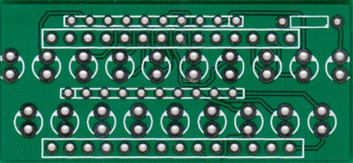
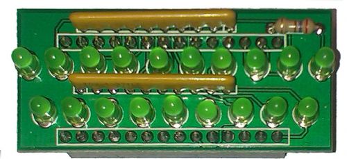
Here is the Manual for MuP-Test. 2014-06-24_105750_MuP-Test.pdf I will be selling MuP-Test in the following configurations: Option 1: Bare PCBs will be $2AUS each (but subject to a $3AUS minimum order due to the Paypal commission) Option 2: PCB with All components provided and either RED or GREEN LEDs *specify choice* ($10AUS) Option 3: PCB with All components provided and either BLUE or WHITE LEDs *specify choice* ($12AUS) Why Choose BLUE or WHITE LEDs? Well with the higher FWD voltage of these LEDs each LED will only draw 2mA and if you wanted to create playful LED demo's the maximum current draw due to all LEDs being on will be only 38mA compared to the RED or GREEN LEDs with a 76mA draw (4mA each). It is entirely user's choice. ------------------------------------------------------------ ------------------------ IO Panel, (98mmx72mm) Uses 4 x PCF8574 chips to create 4 interfaces on the one PCB that will bolt on the back of a 20x4 or 16x4 LCD module, and communicates via the I2C bus to provide 32 bits (8 each channel) of additional IO. The four `Standard' interfaces are: LCD Module 4x4 KeyPad LED Panel General IO 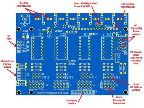
IO Panel Manual can be found here: IO Panel I have priced the IO Panel (Bare PCB) at $6ea. I havent provided other options but as it is easy to solder so I suspect there wont be much demand for kits etc, but if there is PM me and we can work something out. ------------------------------------------------------------ ------------------------ MuP-Security Is an alarm module that plugs into MuP and provides the basis for a home/shop/Van security system. I have attempted to provide as many features as I can in a relatively small 76mm x 61mm PCB. NOTE !! MuP-Security requires Both MuP and the IO Panel to work. At this stage there is no software to drive MuP Security but I hope that there will be something out quite soon.. Unfortunately this is a bit outside my expertise, I do my programming with a soldering iron. If there is someone who is really keen, and feels that is in their capability, to write some decent code for MuP-Security contact me via PM and I will see if we can do a `software for boards deal'. Manual is available here: MuP-Security 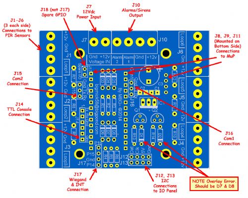
I have decided to offer these at the following price (PM me if interested) MuP-Security (Bare PCB) $5ea I havent provided other options but as it is easy to solder so I suspect there wont be much demand for kits etc, but if there is PM me and we can work something out. ------------------------------------------------------------ ------------------------ Postage of each of the above options will vary but will be basically the actual cost including packaging rounded UP to the next full dollar. Postage cost can be confirmed via PM or email depending on where you are located. For further information on Geoff Graham's MicroMite please see: MicroMite If you have any queries please do not hesitate to contact me via PM (on this site) or via email. Bigmick58@bigpond.com Kind Regards, Mick Mick's uMite Stuff can be found >>> HERE (Kindly hosted by Dontronics) <<< |
||||
| bigmik Guru Joined: 20/06/2011 Location: AustraliaPosts: 2981 |
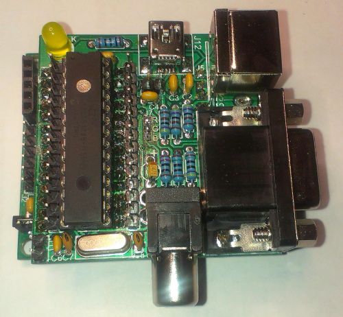
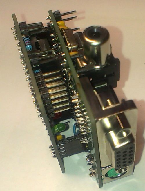
Hi All, I forgot to add my MuP-VT which is designed to plug into MuP and provide VT100 comms. Manual for MuP-VT can be found HERE Please NOTE! There was a minor tracking error on this PCB, read the manual before ordering as full details of this error are described within. These will be priced at $4ea and a programmed VT100 (PIC32MX250) chip will be $8each Photos of MuP-VT plugged into MuP follow 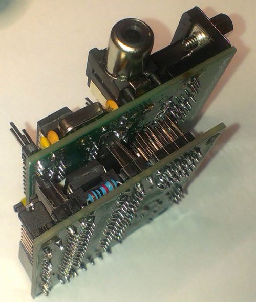
Regards, Mick. Mick's uMite Stuff can be found >>> HERE (Kindly hosted by Dontronics) <<< |
||||
| bigmik Guru Joined: 20/06/2011 Location: AustraliaPosts: 2981 |
Hi All, Announcing the NanoMite Which is probably the smallest MicroMite currently out there, at 15mm x 15mm in size (0.59" x 0.59") it is considerably smaller than an Australian 5c Coin. 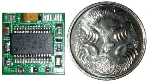
The NanoMite has a PIC32MX170F256B SSOP chip and apart from the Capacitor for VCap and 2 x 100nF bypass Caps and 3 x 4k7 resistors (all are 0805 SMD size) there are no other components on board. There is NO Voltage Regulator and it requires a supply of 2.3-3.6Vdc to run (Ideal for battery operation). It is designed to plug into a standard wiper type 8 pin IC socket or female header pins. It will NOT plug into a machined pin socket as these will not accept the square pins used on the NanoMite. 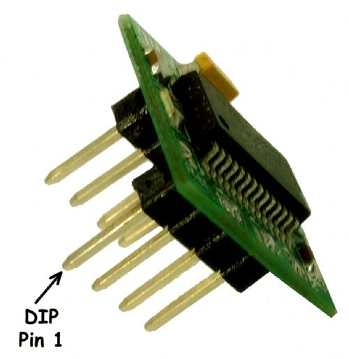
Due to there only being 6 pins available in an 8PIN IC Socket footprint (after Power and GND) there are some obvious compromises that needed to be taken. I have provided 6 `solder-short' configuration pads that allow each of the available DIP8 Pins to have an option of two Pic32 pins. Obviously this means that there could be be times when the pins you want are not available. The NanoMite is not an easy board to build due to the size of the components and the small clearances between the SSOP PIC32MX170's pins. I do not recommend those just beginning with soldering to attempt this project. The following options are available from me. Bare PCBs $1Aus each Fully Built $15Aus each (PIC Programmed) Full kit of components $9Aus each (PIC NOT Programmed as I can't program it until soldered in place) If interested please PM me or email bigmick58@bigpond.com Please thoroughly read the manual before ordering. EDIT *** TassyJim has once again been very generous with his bandwidth and agreed to host the manual for NanoMite. The new home for the manual is here. NanoMite Manual Regards, Mick Mick's uMite Stuff can be found >>> HERE (Kindly hosted by Dontronics) <<< |
||||
BobD Guru Joined: 07/12/2011 Location: AustraliaPosts: 935 |
OMG, I just received two fully built Nanomites from Mick and I can't believe how small they are. I'm glad I got him to build them. He also sent me several blank boards. I'm not looking forward to trying to build those. Mick, the cheque is on it's way. Bob |
||||
| bigmik Guru Joined: 20/06/2011 Location: AustraliaPosts: 2981 |
Thanks Bob, I know I have said it before but seeing the boards and seeing the photos next to an Australian 5c coin (19.4mm dia) is one thing but having a built up unit in your hand is something else again. I shown Don yesterday, on our nowdays not as often as I would like, catch up days and he nearly fell off the chair.. Regards, Mick Mick's uMite Stuff can be found >>> HERE (Kindly hosted by Dontronics) <<< |
||||
| bigmik Guru Joined: 20/06/2011 Location: AustraliaPosts: 2981 |
Hi All, Just announcing that Don of Dontronics.com has generously set up a web page for my suite of boards that I have available. The site is Mick's Product Range This will be the new home for my current and any future items I may release.. Whilst TassyJim has been very generous by hosting my manuals till now I believe that this offers me more flexibility and the ability for pictures and code etc to be added as well is a god send. Jim said he will keep the manuals hosted on his site but he may in the future drop them if he requires the space for his own use. Thanks again Jim. Dave Hall and Phil may also host my manuals (it is up to them and I am OK for them the do that if they wish) and other items but the Dontronics site will be the main reference for my items in the foreseeable future. Regards, Mick EDIT** My signature at the bottom of all my posts will also link to the dontronics hosted site so there will be no need to hunt for this posting. Mick Mick's uMite Stuff can be found >>> HERE (Kindly hosted by Dontronics) <<< |
||||
OA47 Guru Joined: 11/04/2012 Location: AustraliaPosts: 1050 |
Mick, have found your MUP a great unit for programming and testing my Micromites. With two USB ports, one for IPE and the other for the terminal, I can erase, program and test with the one device. 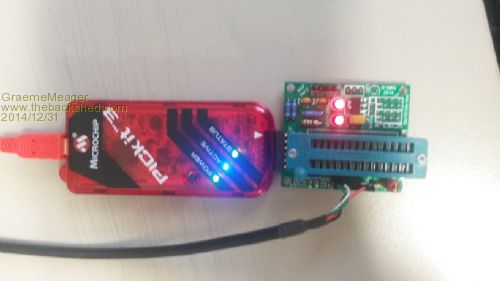
Thanks again Mick and have a great NEW Year GM |
||||
centrex Guru Joined: 13/11/2011 Location: AustraliaPosts: 320 |
Hullo GM I note from the above picture their is no power to the uM is this supplied by the serial port or the Pickit3. cliff Cliff |
||||
| bigmik Guru Joined: 20/06/2011 Location: AustraliaPosts: 2981 |
Hi Graeme, Coming right back at you .... 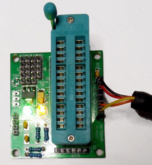
For general Information I used a MuP Ver 1 (Ver 2 is fine also) and fitted a ZIF socket to it to program my Pic32's. I do as GM does and have a teraterm window open and program the PIC with MPlab IPE whilst powering the MuP board off the USB-TLL cable (hence the LEDS being Lit). This allows New chips to be programmed and still keeping their `as new' shape on the pins with no need to straighten the pins to fit a standard socket. Regards and Happy New year Mick Mick's uMite Stuff can be found >>> HERE (Kindly hosted by Dontronics) <<< |
||||
| OA47 Guru Joined: 11/04/2012 Location: AustraliaPosts: 1050 |
Centrex, Sorry I did not mention it, the chip is powered by the USB-Serial cable. 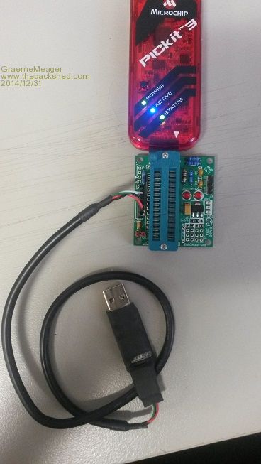
|
||||
| Geoffg Guru Joined: 06/06/2011 Location: AustraliaPosts: 3362 |
I have just finished building one of Mick's Nanomites and an amazing little thing it is too. It is about the size of a thumbnail and it is a full Micromite MkII. I played an old computer game from the 80's on it and it is creepy seeing it respond just like the full sized BASIC computers of the that age. Soldering it is a challenge but it would be definitely worth making a few so that you have a eight pin powerhouse handy that could be put to use anywhere that you only need a few I/O pins. Geoff Geoff Graham - http://geoffg.net |
||||
| Justplayin Guru Joined: 31/01/2014 Location: United StatesPosts: 330 |
Hey Mick! I finally got around to putting the MuP-Test board together and I love it! I shortened the Pauses to 10 ms and it creates a very hypnotic effect. Anybody walking by my desk stop and just stare at the blinking LEDs going around and around. They don't even ask what it's doing, they just stare at it. 
Now I'm thinking of setting something up that changes the blink rate based on the CPU usage of my laptop. A fast blink rate for high CPU usage and slow for low usage. Thanks again, Curtis I am not a Mad Scientist... It makes me happy inventing new ways to take over the world!! |
||||
| bigmik Guru Joined: 20/06/2011 Location: AustraliaPosts: 2981 |
Thanks Geoff, for your kind words. It is of course not for everyone or for every application.. It has its own little niche where size/weight is an issue (as in sending up in rockets etc) Regards, Mick Mick's uMite Stuff can be found >>> HERE (Kindly hosted by Dontronics) <<< |
||||
| bigmik Guru Joined: 20/06/2011 Location: AustraliaPosts: 2981 |
Hi Curtis, Thank you for your kind words, you are the first person, besides myself, who has seen the beauty in such a simplistic thing as the Mup-Test . Every MuP that I sell built up goes through a test with it and it is always good to see that every pin is able to be toggled on and off.. I usually watch several cycles as, like you said, it is quite mesmerising. Regards, Mick Mick's uMite Stuff can be found >>> HERE (Kindly hosted by Dontronics) <<< |
||||
| disco4now Guru Joined: 18/12/2014 Location: AustraliaPosts: 1127 |
Hi Mick, Just letting you know I have all the stuff you sent me working.(MuP V2, Mup-Test and nanoMite). I had no USB TTL cable to start with so started by assembling the MuP-Test. I managed to solder it OK, so then tackled the nanoMite by adding the blue diode and powering with a CR2032 button battery. Well, I could not see the Led flashing. As I looked at the thing two things struck me, you must have bloody good eye sight and you must have sent me a picoMite. The last thing I built was a Dream 6800 in the eighties so the size was a bit of a surprise. Anyway, with a meter I saw the the CR2032 was not lasting that long, but the pin with the Led did have a pulse on it, but not enough the see the blue Led unless you put it in the dark with a new CR2032. When the USB TTL arrived I used it and powered up the MuP, and used the Mup 3.3V to power the nanoMite and the Led was now visible. MuP-Test plugged in an all worked as described. I found the documentation good and answered all the questions I needed to connect up and get going. I have been ebay shopping for LED display, RTC etc so I will have a complete solution when that problem that needs solving comes along. Computers haven't changed that much since the 80's, still a solution looking for a problem. The only other feedback is on the nanoMite document. The schematic labels the jumpers J1-J7 but board shows them as J1,J2,J3, RST, J5,J6,J7, on the schematic, J7 should be RST, J4 becomes J5, J5 becomes J6 and J6 becomes J7. Regards Gerry F4 H7FotSF4xGT |
||||
| bigmik Guru Joined: 20/06/2011 Location: AustraliaPosts: 2981 |
Hi Gerry, Welcome to TBS forum. I am glad that they arrived safely and you have them working as expected. As I have often said you do not realise how small the NanoMite is till you actually have a built one in your hands. 15mm x 15mm is tiny. The Blue LED.. yes the forward voltage of those LEDs I think are around 3v so a 3V battery powering Nm may be pushing your luck a bit If you use a RED (typically 1.7 to 2.1V) you will have more luck there. My eyes are not great (age, diabetes all catching up on me) but I have a range of maggie lenses and lights to assist. Re. The NanoMite comments. NanoMite was dubbed so By TZ on this forum as everybody hates my naming convention of MuP and MuP-Mini was not great. (MuP stands for `Mick's uMite PCB) Picomite has been left open for someone who creates an even smaller 'mite than the Nm (come in Kon, aka kiid) Due to the size (or lack there-of) there was NO room for component labels at all, the 1-6 & Rst on the PCB do not refer to the Part references (J1-J7) but are their function.. In this case `1' is a select for DIP8 Pin 1 `2' is a select for DIP8 Pin 2 `3' is a select for DIP8 Pin 3 `4' is a select for DIP8 Pin 4 `5' is a select for DIP8 Pin 5 `6' is a select for DIP8 Pin 6 `Rst' is an override that puts MCLR (Reset) on DIP8 Pin 1 (ignoring the selected option for `1') This allows the Nm to be flashed via a PK3 or similar. I agree the schematic can be clarified to add the 1-6 and Rst references, Thank you for pointing that out. An updated manual will not be available until Don gets back from his holidays in 2 weeks time as he controls my `Mick Site' Thank you again for your kind words, Good luck with finding a good use for them. Regards, Mick Mick's uMite Stuff can be found >>> HERE (Kindly hosted by Dontronics) <<< |
||||
| bigmik Guru Joined: 20/06/2011 Location: AustraliaPosts: 2981 |
Hi All, As pointed out by Gerry, the schematic is a bit confusing for the NanoMite so I have updated it and the manual is now at Ver 1.1 The change is only the schematic as shown below: 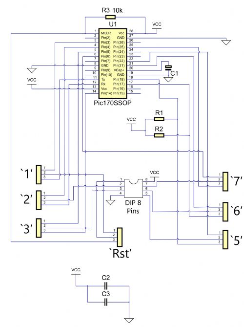
I have attached a ZIP of the Schematic as TBS usually compresses JPEGs to be too small to read 2015-01-04_011048_Schematic.zip I hope that clears up some confusion.. Regards, Mick Mick's uMite Stuff can be found >>> HERE (Kindly hosted by Dontronics) <<< |
||||
| bigmik Guru Joined: 20/06/2011 Location: AustraliaPosts: 2981 |
Lads, Well it looks like Don has stopped drinking on his holidays and remotely updated the NanoMite manual. The updated Manual is available HERE Thanks Don, Have a beer on me.. Mick  Mick's uMite Stuff can be found >>> HERE (Kindly hosted by Dontronics) <<< |
||||
| MicroBlocks Guru Joined: 12/05/2012 Location: ThailandPosts: 2209 |
Hi Mick, I saw some small errors in your manual. In the schematic R3 has the value 10k. In both the Bill of materials and the overlay picture it has a value of 4k7. Also in the overlay picture the capacitor above R3 should be named C2. I personally have a different style to draw schematics (use of colors and minimal line crossings). The 'codes' for the pins are: Digital, Analogue, Interrupt and Count 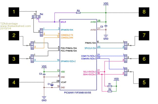
If you like it then please use it. :) pdf version Microblocks. Build with logic. |
||||
| bigmik Guru Joined: 20/06/2011 Location: AustraliaPosts: 2981 |
Hi TZ, Thank you for your input.. You are correct C2 is incorrectly labelled as C3 I will correct that. When I designed the schematic I was going to use 10k for the pullup on the MCLR pin, as I had to buy a reel of 0805 4k7 ohm resistors I decided to use 4k7 instead.. Yes I will change that.. Of course either value is fine but consistency should rule. Re. Your schematic. I admit my Schematic skills are not all that great, I do not have the flair that some people do in that regard.. with your permission I will add your Schematic to the manual as it does clarify the DIP8 Pins better than mine does. I am not really a fan of the colours but your layout and links look better. I will try to improve my Schematic skills, I have only recently discovered that, with DEX, I can hide unused pins and move the used ones around to group them more appropriately.. PM me your address again and I will send you a slab of NanoMites for your school in appreciation of all of your support for this and other boards. Kind Regards, Mick Mick's uMite Stuff can be found >>> HERE (Kindly hosted by Dontronics) <<< |
||||
| Page 1 of 7 |
|||||
| The Back Shed's forum code is written, and hosted, in Australia. | © JAQ Software 2026 |
