
|
|
Forum Index : Electronics : Warpspeed’s MOSFET mounting method
| Author | Message | ||||
| Tinker Guru Joined: 07/11/2007 Location: AustraliaPosts: 1904 |
I hope I do not annoy anybody with my frequent questions but I really would like to fully understand how this works. There is still a problem to be fully understood with the 4 transformers, it keeps bugging my mind and I just have to get to the bottom of it for peace of mind. Its this statement from Tony in particular: "But we cannot just open circuit the individual supplies we do not need when they are connected in series. The unused supplies must be SHORTED OUT to provide a continuous current path through the series string. " Now, looking at the last diagram mackoffgrid posted (on previous page), all the 4 transformers have their output windings connected in series. So, Tony's statement that we cannot open circuit individual supplies does not make sense, they are connected in series and therefore *never* open circuit and *always* provide a continuous current path. To test what will happen I connected the output of 3 transformers I had here in series. The output voltages added up when each input winding was powered. Unplugging any transformer input, or combination of, just altered the output voltage accordingly. It *never* went open circuit and there was at *all* times a continuous current path present. So, why diddle with a third winding to be shorted out (bad idea IMO) when the same result happens by simply not turning on the driving mosfets for the transformer that is not programmed to be active for that instant of the cycle. No voltage in the primary means no voltage out the secondary with a transformer. Also note that I deliberately mostly avoided using the terms "primary or secondary" as I think these were used confusingly in posts here. Klaus |
||||
| Warpspeed Guru Joined: 09/08/2007 Location: AustraliaPosts: 4406 |
Andrew, That all sounds excellent. By my reckoning three strands of 1.4mm should be good for about 23.5 amps. That will give you a very easy 5Kw continuous. Klaus, There are a few things about all this that are a bit off beat and unusual, so its well worth an explanation. Any transformer just reflects what happens on the secondary right back into the primary, with an effect dependant on the turns ratio. Primary and secondary are just words, a transformer is completely bi directional anyway. If a transformer has no load on the secondary, the primary will draw very little current. There will be some slight magnetising current, but we could say the primary behaves (almost) like an open circuit. With a decent secondary load, the primary draws enough current to supply that load. If we short out the secondary, the primary current goes very high and we might blow a fuse. Here is a thought experiment, or you can actually try it: 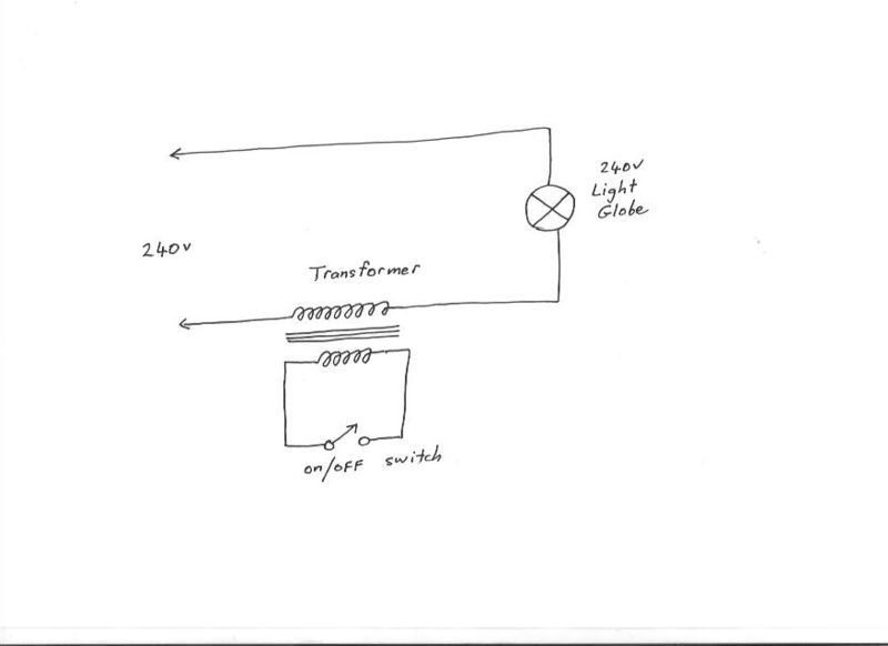 With the switch open, there might only be a dull glow in the lamp. With the switch closed we might expect almost the full 240v to make it through to the lamp. If we connected three transformer windings in series to drive a lamp, the secondary windings just reflect whatever is happening on the primary. Its easier to visualise if all the transformers are 1:1 ratio. Cheers, �Tony. |
||||
| Tinker Guru Joined: 07/11/2007 Location: AustraliaPosts: 1904 |
Hi Tony, I tried the arrangement above, on your last sketch, just the top and the bottom transformer. The load was a car driving light, to get some reasonable current flowing. Much to my amazement, you were right, it behaved exactly as you wrote. Seeing is believing in this case. So, thank you for teaching me something I was unaware of, having never had occasion to try that and having a natural aversion to short circuit live transformer windings. I shorted the winding with an Ampmeter to see how much current flows. 65mA it was. Not a lot but does that mean a small loss of power in that transformer during the short circuit period? Can you suggest if there is an optimal voltage ratio for that 'shorting winding' (compared to the 230V secondary) to minimise this loss? Obviously, a lot of turns are perhaps harder to accommodate on the core. I assume the wire size does not need to be big as so little current flows? Klaus |
||||
mackoffgrid Guru Joined: 13/03/2017 Location: AustraliaPosts: 460 |
Thanks Klaus for doing the experiment - Tony To follow Klaus question, If you could check my thinking on clamping: I'm not using clamping windings - don't see the need. Transformer 1 (Large) : clamp the secondary - because the current is least (use IGBTs) Transformer 2 (Medium) : clamp the secondary - because the current is least (use maybe use MOSFETs) Transformer 3 (Low) : clamp the secondary - although current is equal, likely more efficient (use MOSFETs) Transformer 4 (Tiny) : clamp the Primary - because the current is least (use MOSFETs) |
||||
| Warpspeed Guru Joined: 09/08/2007 Location: AustraliaPosts: 4406 |
[quote]I'm not using clamping windings - don't see the need. Transformer 1 (Large) : clamp the secondary - because the current is least (use IGBTs) Transformer 2 (Medium) : clamp the secondary - because the current is least (use maybe use MOSFETs) Transformer 3 (Low) : clamp the secondary - although current is equal, likely more efficient (use MOSFETs) Transformer 4 (Tiny) : clamp the Primary - because the current is least (use MOSFETs) [/quote] That sounds excellent. Thinking about it, I used clamp windings on my original microprocessor stepped waveform inverter because it was designed for 12v, and I could do clamping more efficiently with a floating high voltage winding. My inverters then were push pull, so all of my mosfets had grounded sources. My current inverter is high voltage using half bridge inverters, so its more efficient to clamp on the high voltage primary. With what you guys are doing, I think there are some excellent reasons for choosing to do all the clamping direct across the secondary windings. It all works, its just a case of deciding which might be best in the circumstances. If making circuit boards, its also very convenient to keep the inverters as much the same as possible. Cheers, �Tony. |
||||
| Warpspeed Guru Joined: 09/08/2007 Location: AustraliaPosts: 4406 |
Transformers are never 100% efficient, there will always be some no load magnetising current, and under heavy loading, power loss due to ohmic resistance. So its never a perfect switch, there will be leakage current when off, and ohmic resistance when on. All we can do is try to strike a good compromise. Probably the best advice woulds be to place the clamp where the voltage is highest and the current lowest, and use suitable rated devices to do the clamping. Mosfets are definitely better up to roughly 150v to 200v. High voltage mosfets are miserable devices, and IGBTs will be more efficient and definitely more rugged, especially as we don't need the extreme switching speed of mosfets. If we were going to get very serious about designing a large transformer with a third clamp winding, we would fit as much copper onto the core that we could possibly fit, and adjust the proportions of copper volume in each winding to roughly equal the amount of power in each winding. The secondary is always working, but the primary is working only sometimes, and the clamp winding only working sometimes. So we would figure out the rms currents to choose wire sizes, and of course suitable turns ratios. The clamp winding can be made any voltage, the copper volume will end up being about the same, and so would the losses in the clamp winding. So we might try to keep the clamp voltage high, but not ridiculously high. If we are going to clamp across the secondaries, primary and secondary should have equal volumes of copper. The turns ratio we know, and the current will be the inverse of the turns ratio. So copper volumes should end up being roughly equal. Its just like designing any ordinary two winding transformer. Cheers, �Tony. |
||||
| mackoffgrid Guru Joined: 13/03/2017 Location: AustraliaPosts: 460 |
Hi Tony I have a query about the smaller transformers (say the 88 watt transformer, 3:1 ratio). The secondary must be able to handle 20 Amps (in my case); I'm presuming the primary only needs to carry 3 to 4 amps. I'm just having a little trouble imagining how the 20 amp secondary doesn't reflect back to the primary? I've been busy drawing up my PCB's. There're all those cheap 100x100 proto boards. Clock board is ordered already. The big Tx is driven by 2 half bridge boards (100x100). I haven't used any speed-up diodes / caps on the gate drive since they're only switching at 50hz (big bridge only). Big Half Bridge schematic attached 2017-03-29_041618_HalfBridge.pdf |
||||
| Warpspeed Guru Joined: 09/08/2007 Location: AustraliaPosts: 4406 |
Andrew, from memory I think you are designing this for a nominal (minimum) battery voltage of around 27.0v ? So the #1 big toroid with its existing 21+ amps secondary winding will require a primary with the right number of turns to generate a 235 volt square wave on the secondary, with a 27.0v square wave on the primary. Found by experimentation, because we do not know for sure how many turns the secondary has. Now the #2 transformer needs to have a secondary voltage of as close to 1/3 as we can get. Or say 78.3 volts. The primary will need a voltage of 27 volts the same as the big toroid. The starting point is to work out the volts per turn required to do that. If the donor toroid already has a 240 v primary, plug it into the mains and measure the volts per turn the original designer decided upon. That is the easy pretty fool proof way. As this is still a pretty big toroid, lets assume we find that 12 turns gives us exactly 8 volts. That would be 1.5 turns per volt for this example, to keep the numbers simple. So we can figure that the primary is going to be 27 volts, so it needs 1.5 x 27 = 40.5 turns. And the secondary is going to be 1.5 x 78.3 = 117.45 turns. We can probably round those numbers up to 41 turn primary and 118 turn secondary. The secondary current will be the same 21 amps as the big toroid. The primary current will be less 41/118 x 21 = 7.3 amps. If you already have a pile of 1.4mm wire (as I suspect). Three of those in hand for the secondary (same as the big toroid) and one in hand for the primary would do very nicely. Cheers, �Tony. |
||||
| mackoffgrid Guru Joined: 13/03/2017 Location: AustraliaPosts: 460 |
Ahhh yes, the fog clears again - thanks (I was confusing myself) Yes, it is a 27v battery. I'm lucky so far. The 3kW Aerosharp toroid had a 235 V primary. I have a 1kw Toroid that has a 90 V (ish) primary (and wound on the inside, so I can keep that. (5mm2 winding) 3rd and fourth I have to wind myself. I have a small toroid suitable for the fourth as long as I can get a sufficient secondary on it. May have to buy a core for the 3rd transformer. |
||||
| Warpspeed Guru Joined: 09/08/2007 Location: AustraliaPosts: 4406 |
It sounds like you are well on your way. Leave extra wire length on your windings, so you can add a turn or two later when testing if need be. All this works pretty well because the smaller transformers switch at a faster rate than 50Hz, so the flux density will be much reduced in the smaller transformers. Once you have some circuit boards and get it all fired up and running, any uneven voltages will show up as unequal height steps. Some will be further apart, others bunched together. By adding a turn here, or removing a turn there its pretty easy to get a pretty decent looking sine wave. Its amazing what a difference each successive transformer makes to the final waveform. Cheers, �Tony. |
||||
| Tinker Guru Joined: 07/11/2007 Location: AustraliaPosts: 1904 |
I'm following all this with interest. Your real challenge will be the fourth (88VA) toroid. I have an empty 80VA toroid core here and I can not see myself fitting sufficient turns for a 235V/ 20A secondary on it, let alone a primary as well. So, do you think its OK to use a bigger toroid, say twice or three times the size, for the fourth toroid? Klaus |
||||
| Warpspeed Guru Joined: 09/08/2007 Location: AustraliaPosts: 4406 |
Ah just realised I made a mistake. The voltages for the second transformer are correct 27v to 78.3v This is a step up transformer so the primary current will be higher than the secondary current. Actually 78.3v divided by 27v x 21 amps = 60.9 primary amps (not 7.3 amps as I said). Yes, its all jolly good fun. And each of us will probably be designing for a slightly different primary voltage, and be using toroids from different odd sources. So there is a lot of luck involved with what can be re used as is. I have been extremely fortunate that all my primaries are 235 volts, so off the shelf commercial toroids have made it really easy. Third transformer will be 27 volts to 235/9 = 26.1v So its very nearly 1:1 at 21 amps. Fourth transformer 27v to 235/27 = 8.8v definitely step down. Cheers, �Tony. |
||||
| Warpspeed Guru Joined: 09/08/2007 Location: AustraliaPosts: 4406 |
Fourth toroid will be (235v/27) 27v 6.8 amp primary to 8.7v 21 amp secondary (about 180VA) The wire will be heavy, but there are not a lot of turns. Cheers, �Tony. |
||||
| mackoffgrid Guru Joined: 13/03/2017 Location: AustraliaPosts: 460 |
I've been working out the Power dissipation on the clamping circuit. Based on all secondary clamping, using IGBTs on the 2 higher voltage Tx's - the losses are not insignificant, although I haven't factored in anything on their duty cycle. Using Mosfets like the IRFB4110s for the 2 smaller Tx's are quite low. But i have found a Fet that might replace the IGBT. Infineon SPA20N60C3 Vds=650V, Rds=190mR, Id=20 2 of these in parallel (in place of one IGBT) would be quite a bit more efficient. |
||||
| Warpspeed Guru Joined: 09/08/2007 Location: AustraliaPosts: 4406 |
You might also like to look at FCH041N60 600v, 77 amps, 41 milliohms. Also R6076ENZ1C9 600v, 76 amps, 42 milliohms. Both available from Digikey for around $15 For low cost initial prototyping, I would probably fit FDA50N50 500v 48 amps 110 milliohms only $4.60 from e-bay. All the above devices are in T0-247 packages. I still prefer IGBTs because they are a lot more rugged than mosfets given similar maximum ratings. Slower and less efficient maybe, but at less than absolute full flat out power the overall losses will be minimal. They also tend to be a lot less expensive in the higher ratings. Cheers, �Tony. |
||||
| mackoffgrid Guru Joined: 13/03/2017 Location: AustraliaPosts: 460 |
That is a neat FET. RS has them also. Ali has them at a fraction of the price -  I'll take on board what you're saying about IGBT ruggedness. Fortunately, making everything TO-247 they're all pin compatible. The fun will start in a couple of weeks when I start receiving my PCBs and parts from china. |
||||
| Warpspeed Guru Joined: 09/08/2007 Location: AustraliaPosts: 4406 |
I would not worry too much initially about using premium high powered parts, just put in any old low cost stuff you might already have that will run at useful power. Same with the mosfet bridges, just fire it up, and get all your waveforms, dead times, transformer phasing and voltages right first. Any smoke will not then be expensive smoke. But I anticipate it will work first go. Cheers, �Tony. |
||||
| mackoffgrid Guru Joined: 13/03/2017 Location: AustraliaPosts: 460 |
I've received my Clamper PCB so my Clock PCB couldn't be far away since I submitted that first. I've written my program to make the Binary file for the Eprom. 27C512. Comprising of 32 maps of 2k each. It covers 25V to 28Vdc and by my calcs the RMS value of each map only differ by a few volts. It generates a csv file to show information pertaining to each Vdc level. I've attached the file for 26.5Vdc. Looking at this information I worked out the frequency of each transformer. Switching cycles per 50hz cycle: 1, 5, 17, 53 Frequency Averaged: 50hz,250hz,850hz,2650hz It will be interesting to see the losses in T4 at that frequency. 2017-04-25_125137_EpromMapData_265.zip |
||||
| Warpspeed Guru Joined: 09/08/2007 Location: AustraliaPosts: 4406 |
All the significant major losses will be in the large #1 toroid, especially the no load idling power. Copper conduction loss at full power will be greatest there too. Hysteresis and eddy current losses in the higher frequency #4 transformer should definitely be higher percentage wise, but as the power level there makes up such a small proportion of the whole, it hardly matters. Cheers, �Tony. |
||||
| mackoffgrid Guru Joined: 13/03/2017 Location: AustraliaPosts: 460 |
I have been testing the Clock brd this week and all is going well. 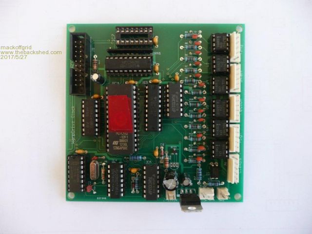 The Connector at the Top Left and the missing ic are part of the uProcessor brd control and is not needed to test the clock board and basic inverting. Next is the Logic capture of D0 to D7 out of the eprom/574 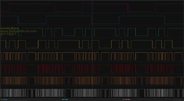 At this point the signal is active Low. D0+D1 drives the smallest transformer and so on. Next shows the signals for just one transformer (Large Transformer) in more detail. From the Bottom, D6 then NAND (D6,D7) , then D7 , then the same three signals after a delay and after been inverted by an ICL7667. At this point the signals are Active High. The Nand of D6 & D7 is the clamp signal. 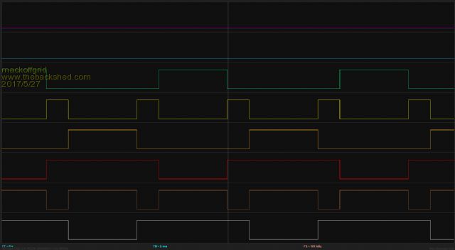 The next image shows the delay (looking at the Clamp signal going active high. 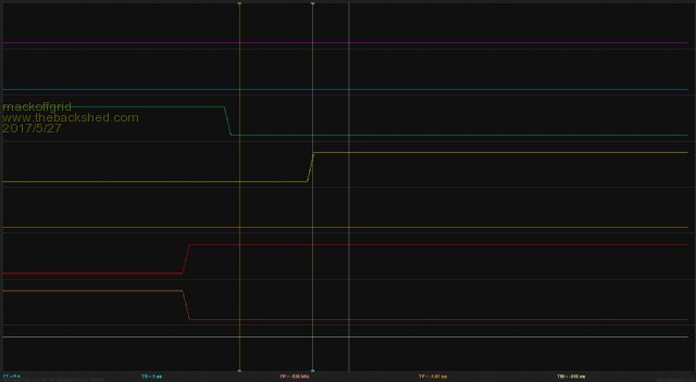 Tony, the dead time measures around 1uSec - I'm considering changing the 3k to 10k to expand the dead time. |
||||
