
|
|
Forum Index : Electronics : Warpspeed’s MOSFET mounting method
| Author | Message | ||||
| Warpspeed Guru Joined: 09/08/2007 Location: AustraliaPosts: 4406 |
Sorry for the delay Kanchana, only just now found your post. The battery charger is a buck regulator set up to provide a constant charging current. In my case 10.0 amps (to charge a 50Ah battery). It runs flat out at the full ten amps, but above a certain battery voltage, the current tapers down to zero as the battery reaches its full rated charging voltage. The cell voltages will not all be exactly the same at that point, but it is just one of several layered safety features that can prevent overcharging. What actually shuts off the charger is the battery monitoring system that terminates charging when any one cell reaches the maximum. That always happens before the average cell voltage reaches the same maximum. This shutdown is done by opening a relay to interrupt dc power to the charger. I did it that way in case the mosfet in my buck regulator ever fails shorted, as that would surely cook the battery. There is a third quite independent layer of protection provided by the main battery digital voltmeter which has undervoltage and overvoltage alarms which can trip the battery isolation circuit breaker. So I have three completely independent ways of preventing battery overcharging, and the video display of all the cell voltages shows me which of the three systems terminated charging. Its pretty easy to see if the highest voltage cell failed to halt the charging when it reached the maximum voltage line on the video display. Cheers, ĀTony. |
||||
| kanchana Regular Member Joined: 08/05/2018 Location: Sri LankaPosts: 56 |
Thanks tony. My knowledge on buck converters is not much , I am going through the MPPT charge controller design threat to gain some incite. I could try to use the existing charge controller to charge the batteries , although not sure connecting the charge controller and the inverter to same solar array ,80V would work as intended . battery monitoring system- does it use some kind of micro controller base control logic what is the battery digital voltmeter you used ? Regards kanchana |
||||
| Warpspeed Guru Joined: 09/08/2007 Location: AustraliaPosts: 4406 |
Kenchana, A lot depends on the size and type of battery how best to control the charging. An existing commercial (Chinese ?) charge controller might be best if you can find one to suit your battery. I am using a non standard battery voltage, so really had no choice but to build my own from scratch. Connecting both the inverter and battery charger to the solar array together presents no particular problems, that is how I am doing it. My own charger uses a buck regulator and a switch mode control chip, plus a couple of op amps. Its all analog, no microcontroller. My battery monitoring system measures the voltage of each individual cell, and does use a microcontroller, but it only switches the battery charger on and off, it does not control the charging current. It starts charging in the morning, then switches off and stays switched off once any cell reaches the maximum voltage. I am told that is the best method with lithium cells. If you have a lead acid battery, you can float charge it once it has finished bulk charging. This is what I am using for a main battery voltmeter. https://www.lightobject.com/Programmable-4-Digit-Red-LED-ACDC-Volt-Meter-with-Dual-Control-Good-for-HHO-System-P408.aspx Its quite a nice unit, and it has undervoltage and overvoltage alarm relays that I use to fire off a 100v dc shunt trip coil on my battery isolation circuit breaker. Cheers, ĀTony. |
||||
| kanchana Regular Member Joined: 08/05/2018 Location: Sri LankaPosts: 56 |
I am eager to built this. Since inverter has 2:1 control ,what if I build the inverter for 100v , then I will connect the 100v(max 120V) panels and run directly from solar with the support of capacitors and at night change over to battery (55- 58 V). Will it work ? Regards kanchana |
||||
| Warpspeed Guru Joined: 09/08/2007 Location: AustraliaPosts: 4406 |
Going from 55v minimum battery, up to 120v peak solar is stretching the 2:1 voltage range a bit too far. You either need a higher battery voltage, or reconfigure your solar panels to have a lower maximum voltage. Cheers, ĀTony. |
||||
| kanchana Regular Member Joined: 08/05/2018 Location: Sri LankaPosts: 56 |
Ok, So I have to wind the transformers to the minimum voltage it will ever see and lover the solar voltage, say to 100v max , What will happen if the voltage go out of the range ? output voltage of the inverter will be start to drop or rise depending on the lower or upper limit discrepancy? How many KW of solar do you use for a day time running I have 150w panels at the moment open voltage is around 20v , s o if i use 5 panels it is only 750W , I wounder it will be enough to cover the modest use during the daytime Regards Kanchana Regards kanchana |
||||
| Warpspeed Guru Joined: 09/08/2007 Location: AustraliaPosts: 4406 |
The control board regulates over a 2:1 input voltage range. Any 2:1 voltage range you like, its just a resistor change in a voltage divider to move it. Below minimum input voltage the output drops out of regulation, and the inverter output falls as the dc input voltage continues to fall. Above maximum rated input voltage, it also stops regulating, and inverter output rises as input voltage rises further. You wind all of your transformers to suit the lowest voltage the inverter will ever see. That small Chinese 5 volt dc power supply works down to about 30v input, and safely up to around 400v dc input. Cheers, ĀTony. |
||||
| kanchana Regular Member Joined: 08/05/2018 Location: Sri LankaPosts: 56 |
Thanks tony Regards kanchana |
||||
| Warpspeed Guru Joined: 09/08/2007 Location: AustraliaPosts: 4406 |
There is no simple answer to all that. I managed to halve my power consumption by monitoring every single load, finding out where the power consumption went, and deciding what could be done. Its silly things like electric wall clocks that draw twelve watts continuously. And replacing them with battery wall clocks that will run for a year on a single AA battery. LED lighting of course, and replacing an old CRT computer monitor with LCD flat screen monitor. Replacing a 25 year old refrigerator with something more recent and a lot more energy efficient. Many other things too, but they were the biggies. You will never know what your daily electrical consumption is, until you start doing some monitoring. How much power you actually get from solar panels depends on climate. Things can be very different on the two opposite sides of a high mountain range for example. Same with sizing a battery. Impossible to even make a guess without doing some data logging through at least one summer and one winter. Cheers, ĀTony. |
||||
| kanchana Regular Member Joined: 08/05/2018 Location: Sri LankaPosts: 56 |
good advice , yes better to start some how and upgrade to according to your own needs Regards kanchana |
||||
| kanchana Regular Member Joined: 08/05/2018 Location: Sri LankaPosts: 56 |
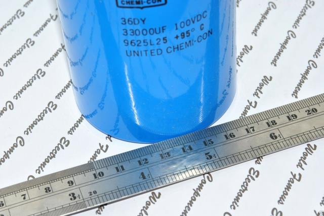
 Is this good candidate it is around 50 $ RIFA 33000uF is about 3 times that Regards kanchana |
||||
| kanchana Regular Member Joined: 08/05/2018 Location: Sri LankaPosts: 56 |
 Regards kanchana |
||||
| Warpspeed Guru Joined: 09/08/2007 Location: AustraliaPosts: 4406 |
Nice find Kanchana. Tried to find data for that capacitor. Chemi Con data is here: http://www.chemi-con.co.jp/e/catalog/pdf/al-e/al-all-e1001s-2018.pdf Could not find 36DY or 9625L25 part number, but closest thing that looks similar is on page 312. 33,000uF 100v "large capacitance aluminium capacitor" Ripple current rating 15 amps. That should work. If it gets unhappy at sustained higher power, the main problem will be temperature rise in the capacitor. That takes time to build up, but otherwise its a nice big capacitor with a lot of energy storage. Cheers, ĀTony. |
||||
| kanchana Regular Member Joined: 08/05/2018 Location: Sri LankaPosts: 56 |
Thanks tony Regards kanchana |
||||
| kanchana Regular Member Joined: 08/05/2018 Location: Sri LankaPosts: 56 |
Regards kanchana |
||||
| Warpspeed Guru Joined: 09/08/2007 Location: AustraliaPosts: 4406 |
Kanchana, That last hand drawn sketch is how I finally did the half bridge gate drivers, I will post the final schematic for that tomorrow. But first here is the full wiring diagram for the entire inverter. 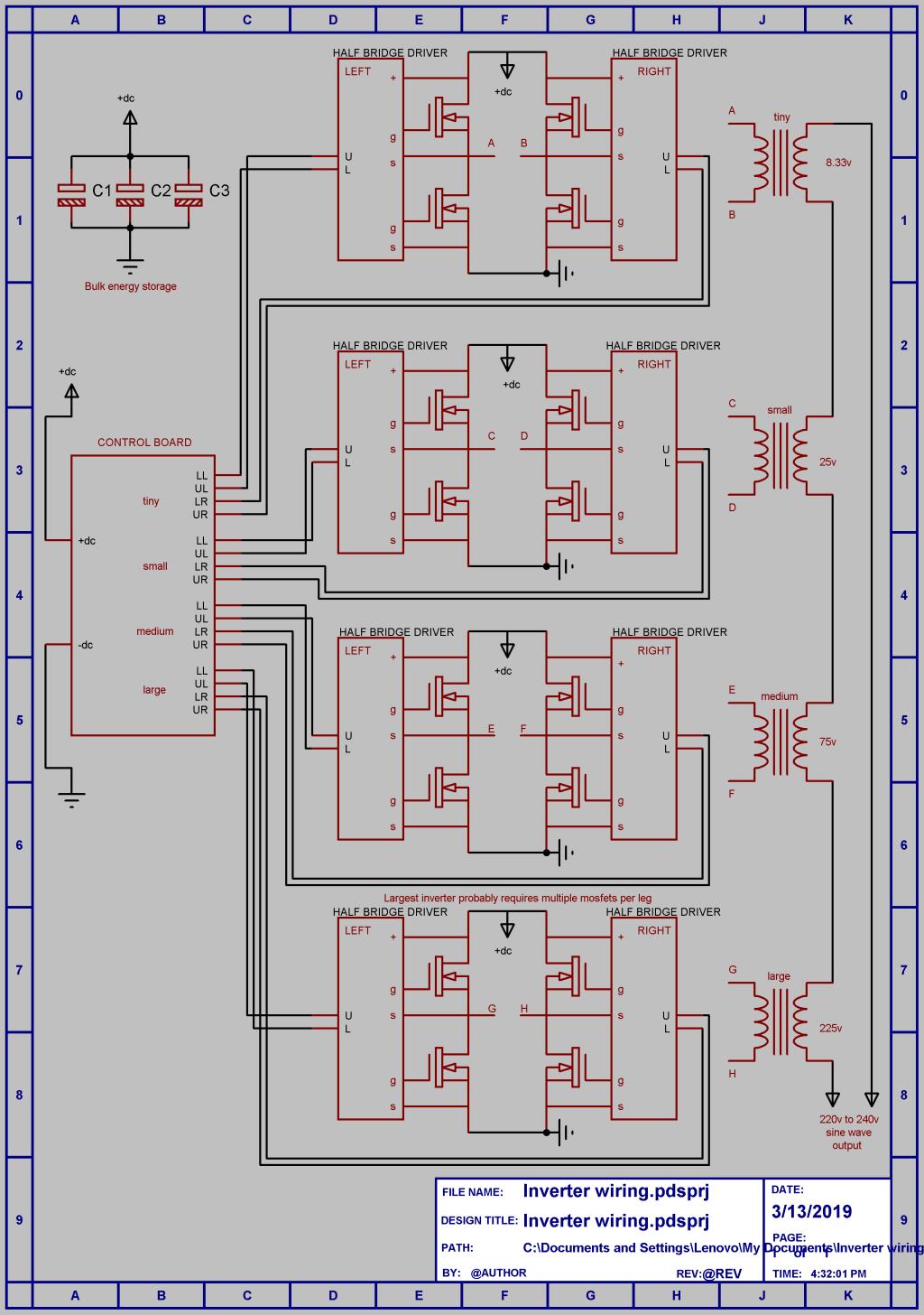 Cheers, ĀTony. |
||||
| kanchana Regular Member Joined: 08/05/2018 Location: Sri LankaPosts: 56 |
Thanks tony . Here is what I have got for the transformers . I have 1000va transformer currently attached to PWM type inverter . other 3 transformers got from china not sure how their true ratings . This one got form a 230 to 115 v converter claimed to be 3000W 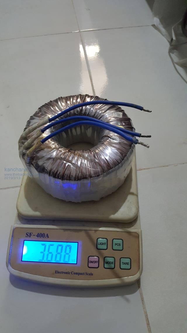 Second one form same source claimed to be 1000w. Those wires I tried used for house hold wiring here . Any way I can use those wires for transformer winding? 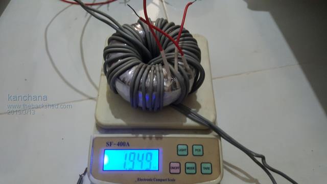 3rd one 230 v to dual 12v claim to be 100w 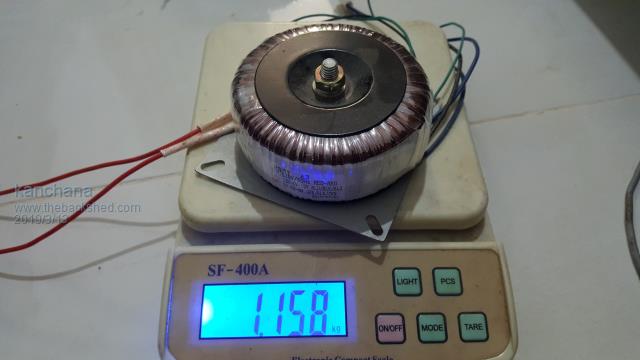 Regards kanchana |
||||
mackoffgrid Guru Joined: 13/03/2017 Location: AustraliaPosts: 460 |
I haven't got a photo handy but my 3kW transformer is about 20kg and my 1kW transformer is about 11kg. I haven't done full on load testing yet. |
||||
| Warpspeed Guru Joined: 09/08/2007 Location: AustraliaPosts: 4406 |
These are my four transformers. 4.5Kva, 1.5Kva 500Va and 167Va. All have 20 amp secondaries. Have the weights written down here somewhere, but will need to search to find the exact piece of paper.  Cheers, ĀTony. |
||||
| kanchana Regular Member Joined: 08/05/2018 Location: Sri LankaPosts: 56 |
Any easy way to check the out put of the transformers with out 50V/Variable ac supply? Regards kanchana |
||||
