
|
|
Forum Index : Electronics : Warpspeed’s MOSFET mounting method
| Author | Message | ||||
| Warpspeed Guru Joined: 09/08/2007 Location: AustraliaPosts: 4406 |
Yes, a variac can be very useful way to measure transformer voltages, and also the zero load magnetising current. That big 3Kw one should be ideal. Just hope that the 230v winding is the inner winding. Its common practice to wind the higher voltage (with the thinner wire) on first, so you may be in luck there. THat is going to save an enormous amount of work. People here often use thermoplastic insulated building wire, or welding cable for the primary. If its on the outside and wound in one layer it should not get that hot. Cheers, ĀTony. |
||||
| wiseguy Guru Joined: 21/06/2018 Location: AustraliaPosts: 996 |
The 3KW one looks like an auto transformer so is probably 2 x 115V windings of equal turns but unequal thickness copper. The output winding has to deliver 115V @ 26A the other one only needs to carry ~13A at 230V applied. As Mackoffgrid eluded to, I'm no transformer expert, but I think 3KW for a total weight of 3.6kG sounds very much overstated, a 2kW grid feed inverter transformer weighs considerably more than that. (Same for 1kW @ ~2kG) If at first you dont succeed, I suggest you avoid sky diving.... Cheers Mike |
||||
| Warpspeed Guru Joined: 09/08/2007 Location: AustraliaPosts: 4406 |
come to think of it, it does look rather small for 3Kva... I finally found my transformer weights. These are E and I laminated transformers. 4.5Kva transformer 51Kg complete 1.5Kve transformer 14.8Kg complete 500Va transformer 7.7Kg complete I have a toroidal transformer out of a 1.6Kva grid tie inverter 13.5Kg complete And a 300Va toroidal transformer 2.5Kg complete Cheers, ĀTony. |
||||
| kanchana Regular Member Joined: 08/05/2018 Location: Sri LankaPosts: 56 |
Thanks guys. Just What I thought 1st one probably good of 300w second one for 100w Both Wingdings use the same copper wire .So my final inverter will be around 1.5 KW. So for 50V to 75 V 2nd transformer I am going to reduce some turns from the primary until it gives 75v out for 50v ac supply . Regards kanchana |
||||
| kanchana Regular Member Joined: 08/05/2018 Location: Sri LankaPosts: 56 |
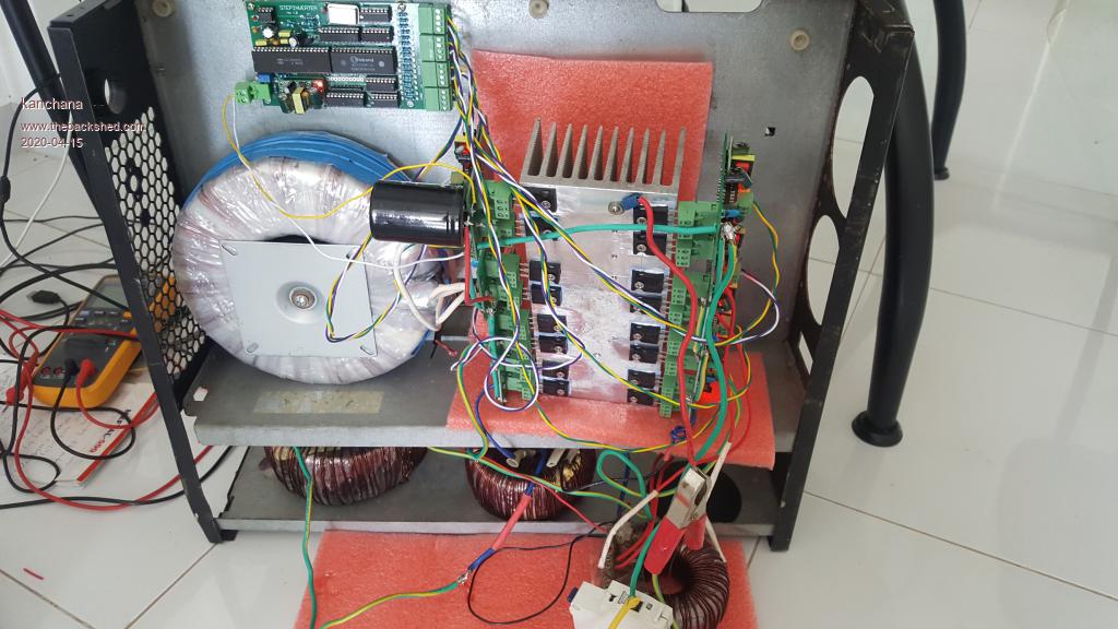
I finally got the time to test my inverter, largest transformer 1000w , I have only connected 4 mosfets for initial setup , without any large caps . But for a morment I could see the output voltage fluctuates and then fuse blows , 4 mosfets in the largest tranformer is gone . Could this happen because of mixed connection of tranformer start and end windings ? 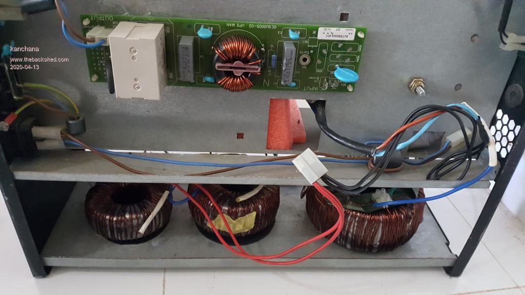 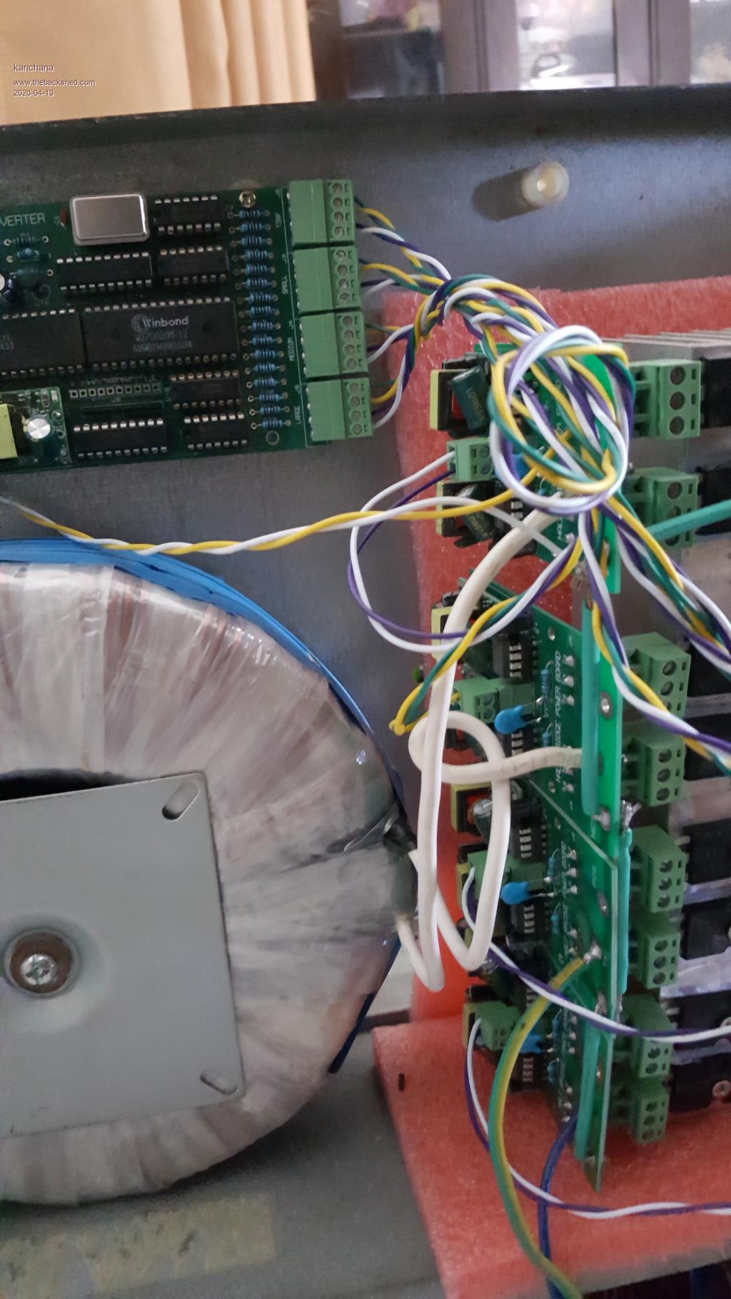 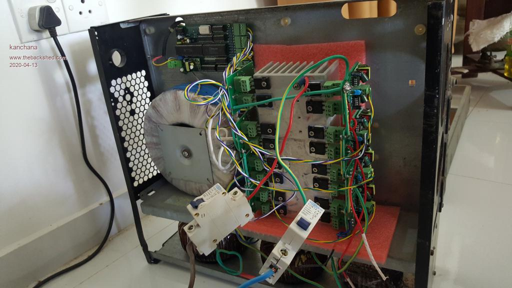 Regards kanchana |
||||
| Warpspeed Guru Joined: 09/08/2007 Location: AustraliaPosts: 4406 |
Mixing start and finish of all the various windings should not cause it to blow up. It only effects how the secondary voltages all finally add together. If all correct you get a sine wave, if any are reversed the inverter output waveform looks "funny" but that is not harmful to the inverter. What do the drive waveforms look like? Can you take a picture ? Cheers, ĀTony. |
||||
renewableMark Guru Joined: 09/12/2017 Location: AustraliaPosts: 1678 |
Check you don't have continuity between the heatsink and drain legs, I see you have insulators, but worth checking. Cheers Caveman Mark Off grid eastern Melb |
||||
| Warpspeed Guru Joined: 09/08/2007 Location: AustraliaPosts: 4406 |
The only blow ups I have had was when the crystal oscillator stopped working. What happens then, is that two diagonal mosfets can be turned on permanently, which is instant disaster. If the drive waveforms are all there and switching on and off, the inverters should all run. The diagonal mosfet permanently on problem, is the only known failure mode, and it occurs if the crystal oscillator stops or fails to start up. A pwm inverter will also fail exactly the same way if that ever happens. I originally had several blowups of earlier Warpverters, when the metal can of a crystal shorted down to the pads immediately below. I then started using commercial crystal oscillator modules for greater oscillator reliability. Klaus had a similar problem when he used an IC socket for his crystal oscillator module. Klaus had several inexplicable blow ups which promptly ceased when he ditched the socket, and soldered the oscillator module directly onto the board. Its been running successfully for a while now, with no further issues. There may be something on your driver board that is not quite right, so its important to at least check that all sixteen drive waveforms are working with respect to ground. If one or more are permanently locked on, then its very likely going to blow mosfets. Cheers, ĀTony. |
||||
| kanchana Regular Member Joined: 08/05/2018 Location: Sri LankaPosts: 56 |
Initially I had a shot on controller board that little power module led was blinking , I had fitted osilator wrong way , fitted a new osilator and then only connected to a battery bank then this happeded . Now fitted the osilator with out the socket . controller out put seem fine? what is the suitable next ? can i check one tranformer at a time? 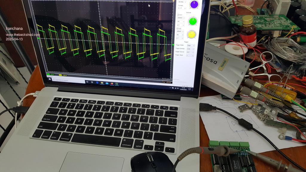 large 1st and 4th output pins 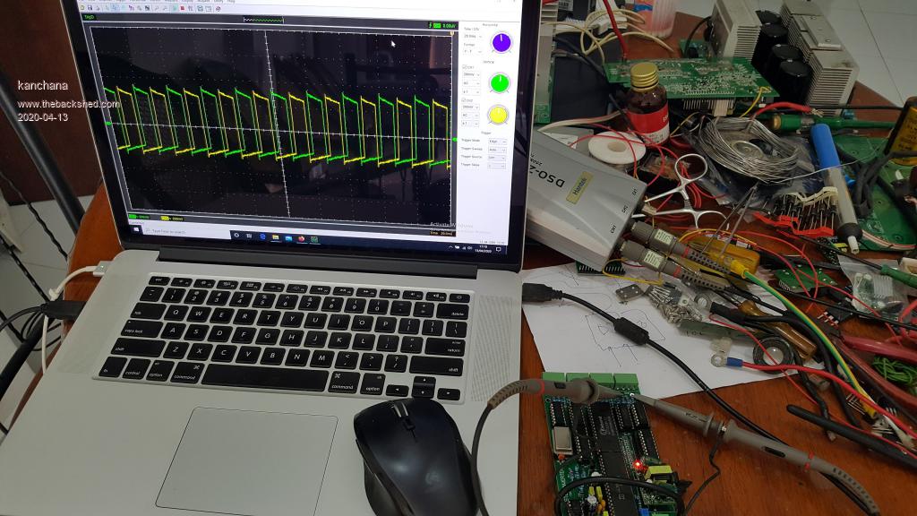 large 1st and 3rd output pins 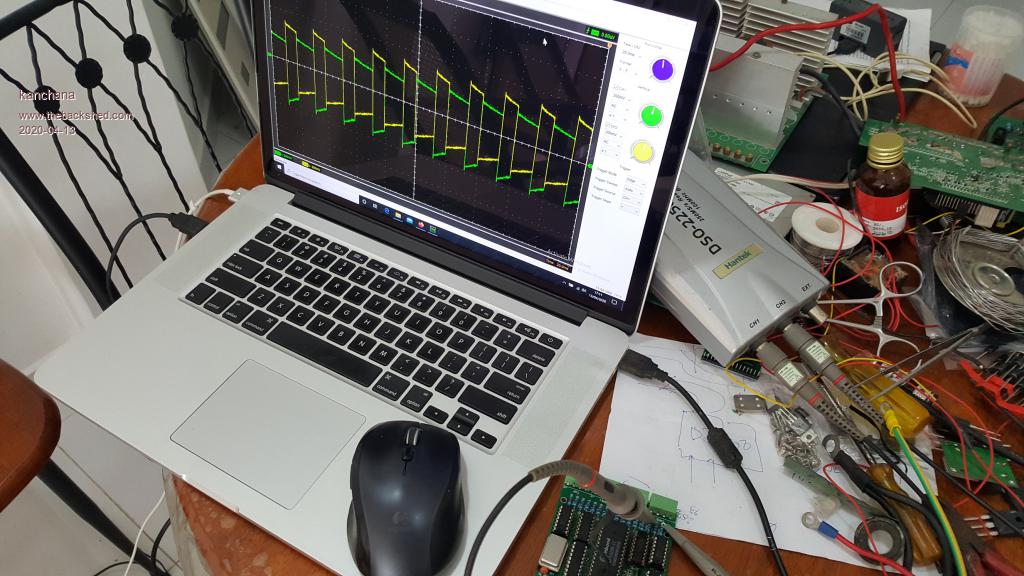 large 1st and 2nd pins 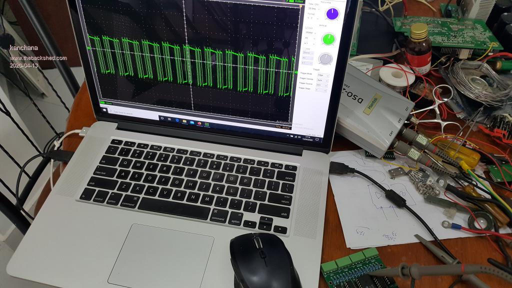 medium 1st pin 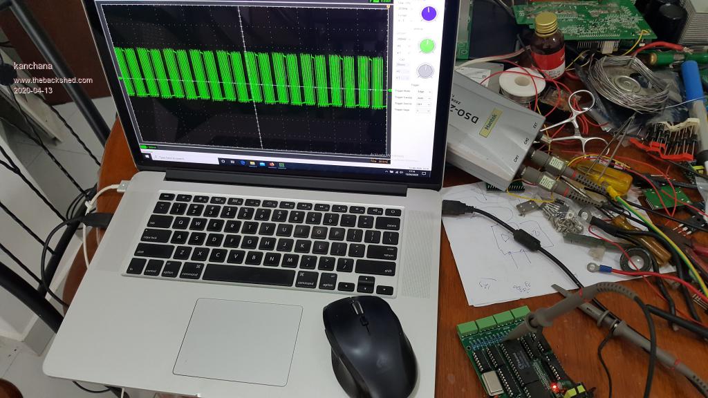 small 1st pin 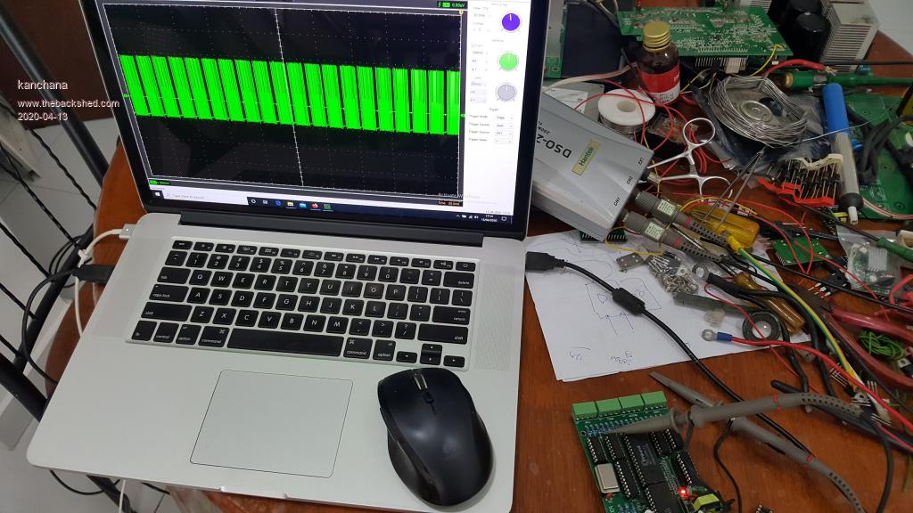 tiny 1st pin Regards kanchana |
||||
| renewableMark Guru Joined: 09/12/2017 Location: AustraliaPosts: 1678 |
Check the signals of pin 1 & 2 then 3 & 4. So in your case green/yellow then test purple/white. The wave forms for each torroid are different. Half way down on this page shows the signals to expect Cheers Caveman Mark Off grid eastern Melb |
||||
| Warpspeed Guru Joined: 09/08/2007 Location: AustraliaPosts: 4406 |
Ah !! That is very interesting, so originally the oscillator module was in a socket ? The background to all this is that Klaus was having some problems with mosfets randomly popping, and neither of us could figure out why. Now at that time, I was working on an entirely different project, and I was waiting for the delivery of a crystal oscillator module from China. But being impatient I used another oscillator module that was close in frequency, but not exactly on the right frequency that I wanted. So being lazy I used an IC socket, so that when the correct module arrived I could just swap them over. Anyhow, I had terrible oscillator problems. The damned thing kept stopping because the narrow wire like legs on the module were a very loose fit into the IC socket. So I soldered it directly onto the board and the problems went away, and I thought nothing more about it. Klaus and I were having regular discussions by e-mail about various things, and the topic of oscillator modules came up. He mentioned using a socket, and suddenly I realized what the problem probably was. He soldered in his oscillator module and so far no more blow ups. So I am pretty confident that problem is now solved. I think yours might be too if you get rid of that damned socket. Its difficult to see much detail in your waveforms, but they are all there, and all appear to be switching cleanly, so there is no obvious problem that I can see there. Make sure your oscillator is working and on the right frequency (3.2768 Mhz) and I think your problems may be gone. Cheers, ĀTony. |
||||
| kanchana Regular Member Joined: 08/05/2018 Location: Sri LankaPosts: 56 |
Thanks Guys , Something is not right it. I am out so will post waveforms when I get back. However last night I wanted make sure before any blow ups so I disconnected the large transformer primary and added 10k resister and measureed the waveform I got 50hz single square wave with out any step as I should. So there should me some error some where ? Regards kanchana |
||||
| Warpspeed Guru Joined: 09/08/2007 Location: AustraliaPosts: 4406 |
All you should see across the largest transformer is a 50Hz square wave with three voltage levels, so that sounds fine. Cheers, ĀTony. |
||||
| kanchana Regular Member Joined: 08/05/2018 Location: Sri LankaPosts: 56 |
Tony I am only getting 2 levels middle level is not there .Will post later Regards kanchana |
||||
| Warpspeed Guru Joined: 09/08/2007 Location: AustraliaPosts: 4406 |
Your first two driver waveforms look o/k. Must have either one faulty gate drive chip, or one open circuit mosfet. As mosfets usually fail shorted not open circuit, my bet is you have either a faulty gate driver chip, or one of the isolated gate driver dc power supplies is not working. Something is preventing the simultaneous conduction of the two lower mosfets which is what produces the zero volt step. Also check that the series gate resistors are o/k. Sometimes a blowup can kill a gate driver and open circuit a gate resistor. You may have missed something when a previous blow up was repaired. Edited 2020-04-14 15:48 by Warpspeed Cheers, ĀTony. |
||||
| kanchana Regular Member Joined: 08/05/2018 Location: Sri LankaPosts: 56 |
Thanks , I was a disconnected mosfet pin , I manage to fire up all the transformers with a PSU , but the final wave form is not good 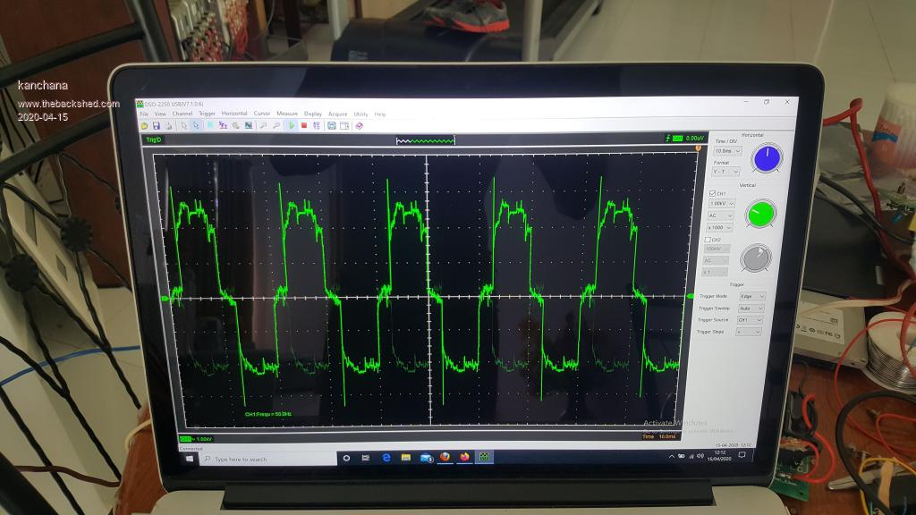 Regards kanchana |
||||
| Warpspeed Guru Joined: 09/08/2007 Location: AustraliaPosts: 4406 |
Is that just the waveform across the secondary of the largest inverter ? That cannot possibly be the combined waveform of all four inverters ???? Edited 2020-04-15 17:42 by Warpspeed Cheers, ĀTony. |
||||
| kanchana Regular Member Joined: 08/05/2018 Location: Sri LankaPosts: 56 |
This is the combined waveform of the all the inverters with out any filtering . Some thing not right it seems Regards kanchana |
||||
| Warpspeed Guru Joined: 09/08/2007 Location: AustraliaPosts: 4406 |
What does the dc supply look like ? Cheers, ĀTony. |
||||
| kanchana Regular Member Joined: 08/05/2018 Location: Sri LankaPosts: 56 |
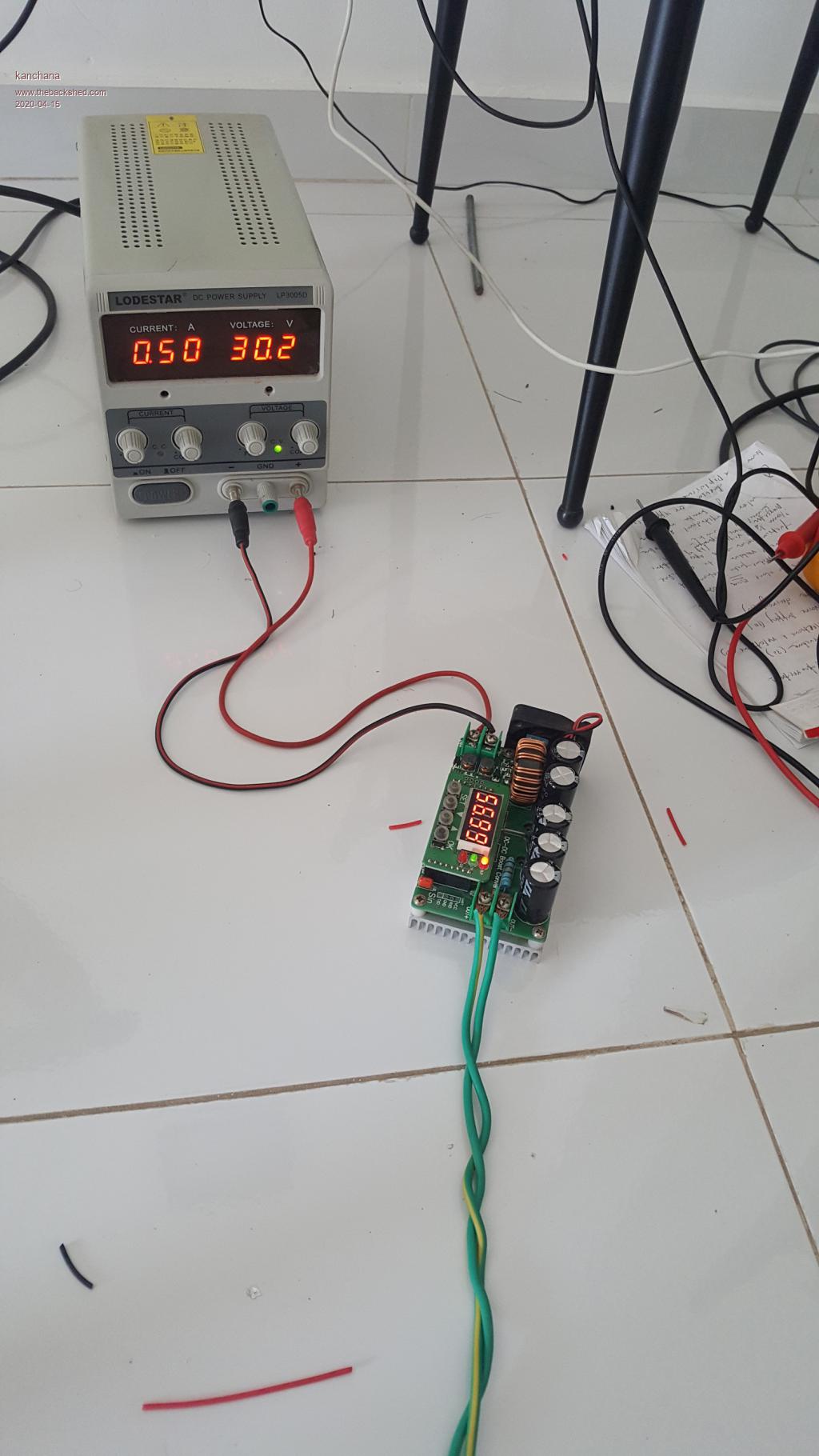  Regards kanchana |
||||
