
|
|
Forum Index : Microcontroller and PC projects : Micromite eXtreme: The PCB portfolio
| Page 1 of 3 |
|||||
| Author | Message | ||||
| matherp Guru Joined: 11/12/2012 Location: United KingdomPosts: 8583 |
For built versions and/or bare PCBs contact WW or use the gerbers to make your own 64-pin 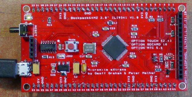 Features: PIC16F1455 USB/UART and PIC32 programmer All pins broken out on a breadboard compatible 0.1" grid Direct mount for 2.8" ILI9341 display including SDcard connection Optional PWM control of display backlight Gerbers 2017-03-20_092558_backpack64MZ.zip Schematic 2017-03-20_092620_Schematic.pdf 100-pin: Type 1 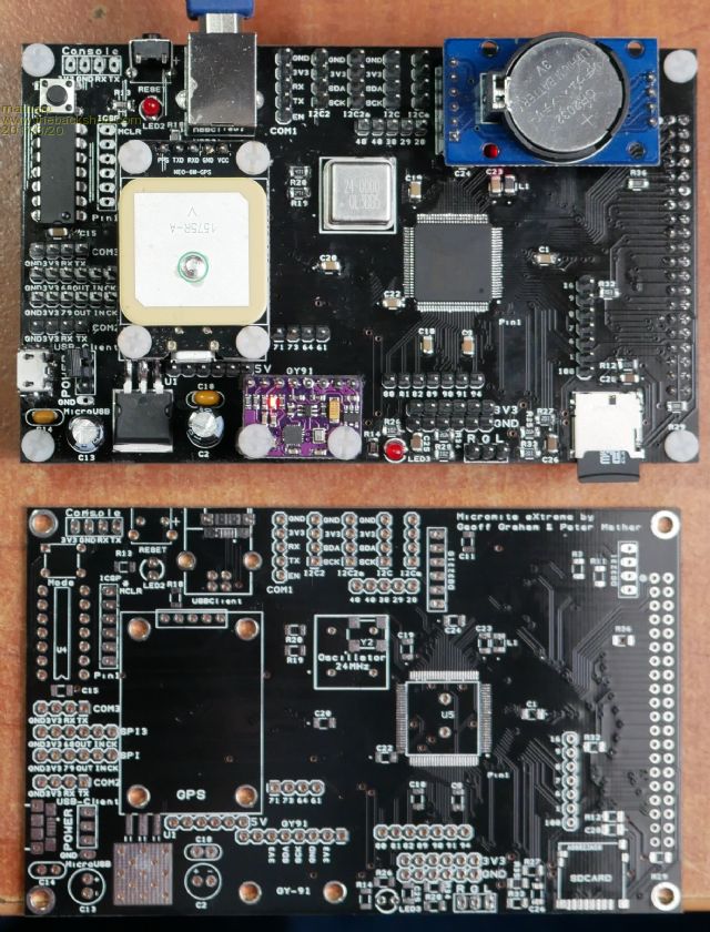 Features: PIC16F1455 USB/UART and PIC32 programmer All pins broken out Function specific headers for COM, SPI and I2C ports GPS header GY-91 header RTC header Direct mount for 4.3" SSD1963 display Micro SDcard slot Onboard line-level sound output circuitry 6-off each pins to supply GND, 5V and 3.3V for additional circuitry Gerbers 2017-03-20_093120_Backpack100min.zip Schematic 2017-03-20_093141_Schematic.pdf 100-pin: Type 2 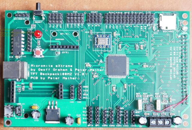 NB: The picture shows the first prototype which has a few faults (wire links in picture). These are corrected in the attached gerbers but the revised version has not been fabricated at this point Features: PIC16F1455 USB/UART and PIC32 programmer All pins broken out Function specific headers for COM, SPI, COUNT, Keyboard, mouse and I2C ports PWM ports arranged for direct connection of servos with 5V supply GY-91 header RTC header Direct mount for 5" and 4.3" SSD1963 displays Micro SDcard slot Onboard sound output circuitry with audio amplifiers for direct speaker connection 14-pin header for additional analogue and digital I/O with 14 each 3.3V and GND connections Gerbers 2017-03-20_095340_Backpack100.zip Schematic 2017-03-20_095022_Schematic.pdf 144-pin 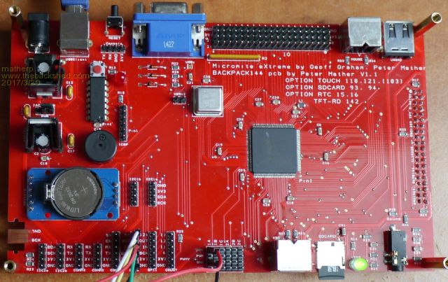 PIC16F1455 USB/UART and PIC32 programmer Function specific headers for COM, COUNT, SPI and I2C ports 40-pin header for addition Analogue and digital I/O with 20 each 3.3V and GND pins PWM ports arranged for direct connection of servos with 5V supply Onboard pullups for 8 I/O pins allowing direct connection of DS18B20 etc. NunChuck Connection PS2 Keyboard port PS2 Mouse port RTC header Direct mount for 7" SSD1963 display Micro SDcard slot Direct PIC32 USB connection VGA monitor port Onboard line-level sound output circuitry with audio jack socket Gerbers 2017-03-20_100754_Backpack144.zip Schematic 2017-03-20_100824_schematic.pdf |
||||
| panky Guru Joined: 02/10/2012 Location: AustraliaPosts: 1094 |
Peter, Absolutely awsome work - I have several of your 470 boards and a 144 Extreme and they all work flawlessy. Will round out the family with the other boards as soon as I can convince herself of my needs (for more toys  ) )Thank you for sharing your passion. Regards, Doug. ... almost all of the Maximites, the MicromMites, the MM Extremes, the ArmMites, the PicoMite and loving it! |
||||
palcal Guru Joined: 12/10/2011 Location: AustraliaPosts: 1802 |
@ matherp I purchased a SnadPic baord and they have sent me the ECH version instead of EFH. Will it still work or do I send it back. Paul. "It is better to be ignorant and ask a stupid question than to be plain Stupid and not ask at all" |
||||
| matherp Guru Joined: 11/12/2012 Location: United KingdomPosts: 8583 |
send it back. |
||||
| panky Guru Joined: 02/10/2012 Location: AustraliaPosts: 1094 |
Hi Peter, Do you have a BOM for the boards above? If so, could you post it please? Even a rough list with the P/Ns of the bits you used would be helpfull. Regards, Doug. ... almost all of the Maximites, the MicromMites, the MM Extremes, the ArmMites, the PicoMite and loving it! |
||||
| Intellecta Newbie Joined: 07/05/2016 Location: AustraliaPosts: 22 |
Dear Peter, AS always ... fantastic work on the extreme devices and boards. I was interested in the 64 pin variation as a school project and I just wanted to try seeed pcb as a manufacturing option. They indicated a significant number of issues on the Gerbers - tracks to ground plane etc. I viewed the Gerbers in Diptrace with the same conclusion. Is there a correct version somewhere.?? Once again... fantastic work, Tony Pugatschew |
||||
bigmik Guru Joined: 20/06/2011 Location: AustraliaPosts: 2870 |
Hi WW, PeterM, All, I note that Peter's 144 has all MALE headers and WW's has All FEMALE headers.. Is there going to be a standard here? Personally I have always felt that Males should be on the Main board and females on the Plug ins as if any header wears out it would be the female so the plugin is easier to replace than the main but in reality it is a moot point.. I don't want to build mine with the `wrong' headers. Kind Regards, Mick Mick's uMite Stuff can be found >>> HERE (Kindly hosted by Dontronics) <<< |
||||
| VK2MCT Senior Member Joined: 30/03/2012 Location: AustraliaPosts: 120 |
Hi All, Does anyone (WW ?) have built Xtreme 144(s) for sale ? I'm after 2. Thanks, John B VK2MCT |
||||
TassyJim Guru Joined: 07/08/2011 Location: AustraliaPosts: 5905 |
My 144 has female headers for the display connector and the RTC. No other headers installed yet and they will be male. I would like the display header to be one with long pins so you have a female header on the underside and male header on the top side. That way a 40 way cable can be used to connect to a display, as well as the option to mount it piggy-back. There is no way I am going to try and remove the 40 way connector now it's soldered on. I made do with a couple of 40 way male-male gender benders to use an old IDE cable. You have to be careful to get the pins the correct way around when playing with cables. Jim VK7JH MMedit MMBasic Help |
||||
| WhiteWizzard Guru Joined: 05/04/2013 Location: United KingdomPosts: 2794 |
There are various option cables out there (look for 40-way RPi GPIO cables). I have managed to use one such cable that allowed me to 'remote connect' a TFT with male pins to the female MMX. It all depends on which side of the 'ribbon' the connector is mounted. With careful planning you can make your own cable without the need for a 'gender-bender'  WW For everything Micromite visit micromite.org Direct Email: whitewizzard@micromite.o |
||||
| matherp Guru Joined: 11/12/2012 Location: United KingdomPosts: 8583 |
DO NOT USE ANY OF THE ABOVE GERBERS!!!!! I've just upgraded to DesignSpark V8.0 from 7.2 and it looks like there is a bug in the new release. I've submitted a support ticket. Thanks for the heads up. |
||||
| WhiteWizzard Guru Joined: 05/04/2013 Location: United KingdomPosts: 2794 |
Mine is just the testbed and was easier for me to include female headers for the I/O connections. I supply the MMX with a female TFT connection (as most TFTs have male pins) AND female RTC sockets to accept the DS3231 module (that also has pins on it typically). I then supply a range of pins/sockets (loose) so the end user can choose what they wish to use. Some may even want to use right angle male/female . . . WW For everything Micromite visit micromite.org Direct Email: whitewizzard@micromite.o |
||||
| TassyJim Guru Joined: 07/08/2011 Location: AustraliaPosts: 5905 |
I have used the IDE extension cables in the past but I spent a long time searching the shed for one without any luck. I have plenty of standard IDE cables and 40 way female connectors so used what I had for now. It works so that's good enough for me. Jim VK7JH MMedit MMBasic Help |
||||
| WhiteWizzard Guru Joined: 05/04/2013 Location: United KingdomPosts: 2794 |
Hi Jim, It would be interesting to know what distance can be obtained between the MMX and TFT connectors whilst still retaining a perfect image (and also accurate response to touch). I was using a 6" (150cm) ribbon cable on a 4.3" SSD and it all worked perfectly. What distance have you got there? Thanks WW For everything Micromite visit micromite.org Direct Email: whitewizzard@micromite.o |
||||
| TassyJim Guru Joined: 07/08/2011 Location: AustraliaPosts: 5905 |
@WW Currently I am using a 300mm cable including the two gender-benders. I would be more comfortable with 200mm M-F cable. Jim VK7JH MMedit MMBasic Help |
||||
| matherp Guru Joined: 11/12/2012 Location: United KingdomPosts: 8583 |
I now believe the Gerbers posted in this thread are OK. I've checked them with GC-Preview and the look fine. Please see attached response from DesignSpark support (very impressed with their responsiveness for a "free" product). Gerbview definitely seems to be the problem rather than the gerbers themselves. |
||||
| CaptainBoing Guru Joined: 07/09/2016 Location: United KingdomPosts: 1985 |
Hello group. for the MMX+144, I use the following CONST definitions to map the bank of IO pins on the board to the actual PIN number to use in your code. Might help someone, it certainly takes the knots out of my brain 'Standard IO Mappings to Pins for MMX+144 'Legend for each is ' A - analogue capable ' 5 - 5V tolerant ' P - pulled up (use OC in your code when defining) ' ' use as follows ' ' SETPIN(IO1) etc... CONST IO1=1 'A CONST IO2=4 'A CONST IO3=21 'A CONST IO5=36 'A CONST IO6=40 'A CONST IO7=44 'A CONST IO8=46 '5 CONST IO9=51 '5P CONST IO10=53 '5P CONST IO11=59 'A CONST IO12=65 'A CONST IO13=67 'A CONST IO14=81 '5P CONST IO15=83 '5P CONST IO16=87 '5P CONST IO17=100 '5P CONST IO18=102 '5P CONST IO19=113 '5P CONST IO20=128 '5 CONST IO21=144 'A CONST IO22=135 '5 CONST IO23=103 '5 CONST IO24=101 '5 CONST IO25=92 '5 CONST IO26=84 '5 CONST IO27=82 '5 CONST IO28=68 '5 CONST IO29=66 'A CONST IO30=60 'A CONST IO31=56 'A CONST IO32=52 '5 CONST IO33=50 'A CONST IO34=45 '5 CONST IO35=43 'A CONST IO36=39 'A CONST IO37=31 'A CONST IO38=22 'A CONST IO39=5 'A CONST IO40=2 'A |
||||
| matherp Guru Joined: 11/12/2012 Location: United KingdomPosts: 8583 |
Great, I'll add it to the manual as an appendix if that is OK? |
||||
| CaptainBoing Guru Joined: 07/09/2016 Location: United KingdomPosts: 1985 |
'course |
||||
| Phil23 Guru Joined: 27/03/2016 Location: AustraliaPosts: 1664 |
Hi Jim, Not sure if I remember clearly, but when I built my E100, with the display connector on the wrong side I think when I considered a cable, I think I decided it wouldn't work as the pins would be mirrored. Someone correct me if I'm wrong, but I thought the conductors in the ribbon cable would end up swapped at one end like this:- [Code] 1 --> 2 2 --> 1 3 --> 4 4 --> 3 5 --> 6 6 --> 5 7 --> 8 8 --> 7 .. .. .. ..[/code] And assumption here is that you'd be connecting to the pins on the opposite side of the board. Phil. |
||||
| Page 1 of 3 |
|||||
