
|
|
Forum Index : Windmills : f n p gridtie windturbine, triple stator
| Author | Message | ||||
DaveP68 Senior Member Joined: 25/11/2014 Location: New ZealandPosts: 292 |
Hi Fred It works by removing the peak current pulses that occur due the narrow conduction angle of the 3 phase rectifier. Here's an illustration of "NO" power factor correction on a single phase rectifier. 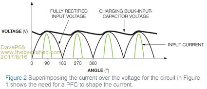 Here is a 3 phase power factor correction capacitor circuit. 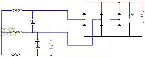 Hope this now makes sense in what I'm describing. David There are realities if you do not accept, will lead to frustration because you will be spending time on wrong assumptions and the results cannot follow! The Dunning Kruger Effect :) |
||||
| flc1 Senior Member Joined: 20/11/2011 Location: New ZealandPosts: 242 |
I wonder if a power factor correction setup would work with a cap doubler on 1 stator? Has anybody tried that? |
||||
| flc1 Senior Member Joined: 20/11/2011 Location: New ZealandPosts: 242 |
well the high voltage inverter has finally arrived in nz, Now I just have to pay the huge ransom demanded by the highly likeable nz customs and then the inverter is "released" to me. I must be punished for my sins... fancy trying to import somthing thats not manufactured here in nz? how dare I even attempt such a thing. |
||||
| flc1 Senior Member Joined: 20/11/2011 Location: New ZealandPosts: 242 |
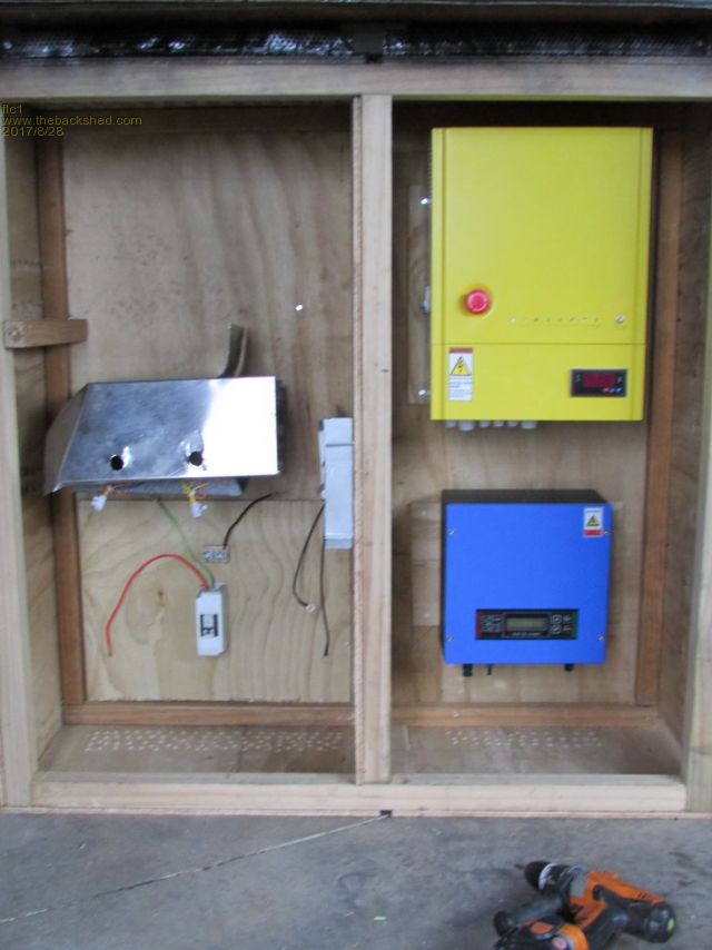
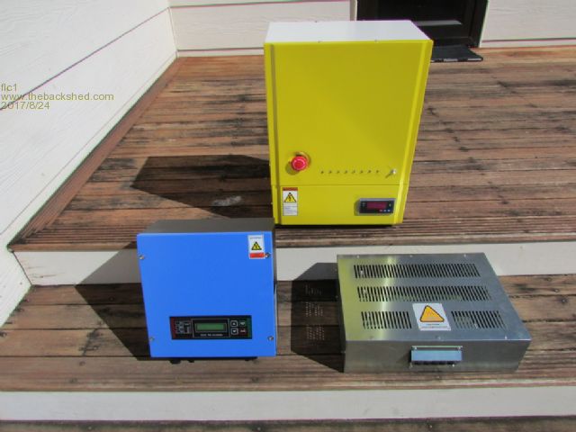 New 40-540dc blue inverter , and the yellow voltage controller and the dumpload resistors 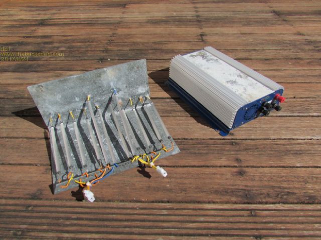 one of the 45-90dc inverters from my old dual fnp ,with home made dumpload resistors. a huge diffrence in size ( and cost) between the two setups, but "hopefully" with the new larger setup I will get over 1 kw from 1 stator. |
||||
| DaveP68 Senior Member Joined: 25/11/2014 Location: New ZealandPosts: 292 |
Hi Fred Well done, that looks an impressive new inverter. It should extract the maximum possible output power from a single 36 pole copper stator with black cap. Forget those crappy old 42 pole stators, if you can get access to 36 pole stators that output 40 % more power for the same given RPM. This just has to work better and provide far more "accumulated power" over say a 42 pole dual that has been tried by a few on here. If you did go with a dual 36 pole set up with a suitably up rated 40-540 VDC inverter you could get a peak output of up to 2.5 kW. With a triple stator set up a peak output of 4 kW could be possible. You're about prove my point about F&P stators like to operate over a wide voltage range with the current kept at an optimum value for their best power extraction. Ok results can be achieved into batteries, but requires rewiring of stators and needs to be a dual setup to give any meaningful output. Looking forward to seeing some real world results. David There are realities if you do not accept, will lead to frustration because you will be spending time on wrong assumptions and the results cannot follow! The Dunning Kruger Effect :) |
||||
| flc1 Senior Member Joined: 20/11/2011 Location: New ZealandPosts: 242 |
 inverter cabinet |
||||
| DaveP68 Senior Member Joined: 25/11/2014 Location: New ZealandPosts: 292 |
That inverter looks like a 'Load Adaptive Impedance Matching' type which suits those F&P 36 pole copper stators. I know of a member on here earlier this year asked "where do I get one of these? May-be It's down in the South Island in Middle Earth" Well a message to that member they come from a company in China. There are realities if you do not accept, will lead to frustration because you will be spending time on wrong assumptions and the results cannot follow! The Dunning Kruger Effect :) |
||||
| domwild Guru Joined: 16/12/2005 Location: AustraliaPosts: 873 |
David, am easily confused. Are you saying your system as per the diagram is better than the capacitor doubler system? If so, what are the cap. values please. Taxation as a means of achieving prosperity is like a man standing inside a bucket trying to lift himself up. Winston Churchill |
||||
| flc1 Senior Member Joined: 20/11/2011 Location: New ZealandPosts: 242 |
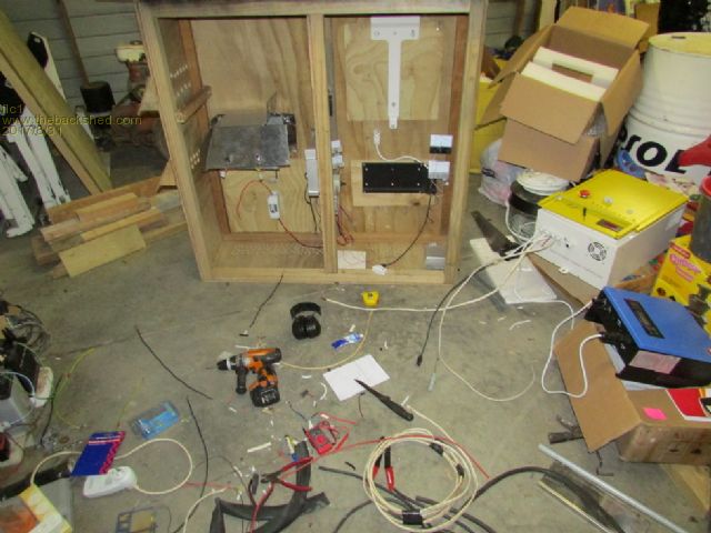 Sorting wiring for the controller ,inverters ,gauges etc. Doing hour here n hour there when not at work, my back sheds a bit of a mess at the moment lol. |
||||
| flc1 Senior Member Joined: 20/11/2011 Location: New ZealandPosts: 242 |
Sorry domwild, i can't help you with the cap values , Dave did tell me what they were ,but I can't recall exact values.He built it. Im sure Dave will give you the info, But I think he is away from home at the moment. |
||||
| DaveP68 Senior Member Joined: 25/11/2014 Location: New ZealandPosts: 292 |
Yes the 'Power Factor Correction Capacitors' set up correctly are far superior to using a capacitor doubler(s) on F&P stators. It comes down to using a staggered stator configuration if it's directly connected to batteries. The system Fred has shown on this topic, is the easiest to configure. It should output more than 1 kW from a single F&P stator wired 1x 12p Delta using small 1.9 uF high voltage AC (275 V) 'power factor correction capacitors'. The expected peak Voltage across the capacitors is around 260 VAC. This is a high voltage low currant system that extracts the maximum possible Accumulated Power from the wind. The best results with batteries can be achieved on a 48 VDC system, but good results can be done on a 24 VDC system too. This of course requires a Dual stator system. In order for me to calculate the approximate "Power Factor Correction Capacitors" value in uF I need to know a few variables like system voltage? What type of F&P stator you plan to use 36 or 42 pole. My recommendation is to go with a 36 pole copper with a matching black rotor cap as you get an extra 40% power output for same RPM and factory decogged. Can make it work with any version of the 42 pole stators but you will get less power than the 36 pole. Have no interest in capacitor doublers now, as power factor correction capacitors provide a far better power extraction over the "wind power curve" for F&P's. This should "setup correctly" provide far more accumulated power output from a wind turbine (for F&P's in this case). They can be used on other types of PMA's. There is still a place for the capacitor doubler for PMA's that have a low pole count like AxFX's and can't be rewired like the F&P stators can be. David There are realities if you do not accept, will lead to frustration because you will be spending time on wrong assumptions and the results cannot follow! The Dunning Kruger Effect :) |
||||
| flc1 Senior Member Joined: 20/11/2011 Location: New ZealandPosts: 242 |
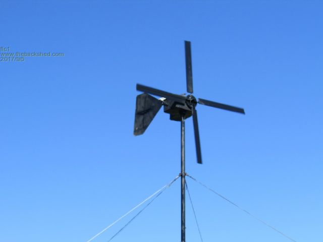
Finnaly got the turbine up and running. I started at 4 pm yesterday arvo and finnished at about 3am this morning. First results are good with the turbine putting out about 230w from the catabatic winds from all 3 inverters. 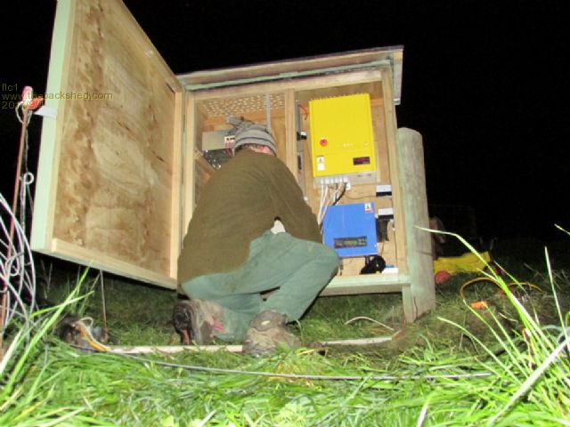 finnishing inverter box The new 40-540v inverter works well, the controller lets the voltage rise to 100vdc at the start and then opens a connection to the inverter which then starts working from 40-540 v with its mppt, sorry no rpm as the rps unit is not fitted yet. 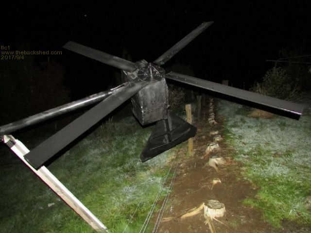 The blades are awsom,quiet,seem to perfom well in low winds... thanks Phill. The paint on the blades will probably only last for one or two storms ,but it looks ok to start with. We should be getting a stronger wind here over the next couple of days.so should be able to get some good output readings on the ac output meters, hopefully it all holds together.  daybreak |
||||
| DaveP68 Senior Member Joined: 25/11/2014 Location: New ZealandPosts: 292 |
Hi Fred Well done and goes to show those GOE 222 blades Phill supplied you work very well in low wind, which is what he said they would do. That low down 'Accumulated Power' is what it's all about after all not so much the big numbers. Look forward to hearing the kW/h's output over a month and what the peak readings end up being. Cheers David There are realities if you do not accept, will lead to frustration because you will be spending time on wrong assumptions and the results cannot follow! The Dunning Kruger Effect :) |
||||
fillm Guru Joined: 10/02/2007 Location: AustraliaPosts: 730 |
Hi Fred, Good Stuff, been a long project and finally up and going and hope all the conviction to a Grid Tie higher voltage pays off. I would throw a bit of advice take it or leave it, if you see it constantly hunting the wind the problem will be fixed with a longer tail, minimum length is Radius + a bit. Also kick it about 10deg away from the furl direction will help tracking. Look forward to seeing some good results and hope you are not throwing all your eggs into the max output basket. Been busy on a few other projects so playing with the F&Ps / LGs is on hold but I will have a whole new designs in a few months or so pending time. Was up to a prototype compact quad Diesel Powered DC Gen, not an easy one to pull off, but its been put on the shelf under the bench for now. It was kicking some impressive numbers though 5kW+ from 3 stators, the 4th stator would stall the 7kw Motor.  PhillM ...Oz Wind Engineering..Wind Turbine Kits 500W - 5000W ~ F&P Dual Kits ~ GOE222Blades- Voltage Control Parts ------- Tower kits |
||||
| flc1 Senior Member Joined: 20/11/2011 Location: New ZealandPosts: 242 |
thanks,,yep its been a long one Phill, but finnaly got there ,It seems to track ok with the wind, I have put abit of pitch on the last 12 inches of the tail fin to yaw it towards the wind and it seems to be good ,I guees because its quite a large surface area. thats a impressive setup in that pic ,thats a good output you got . Do you strengthen your rotor caps?. Cheers Dave and thanks for your help.will keep in touch |
||||
| flc1 Senior Member Joined: 20/11/2011 Location: New ZealandPosts: 242 |
 |
||||
| domwild Guru Joined: 16/12/2005 Location: AustraliaPosts: 873 |
Thanks David for your kind answer. Should I ever finish my old 36V system, I will have to ask for advice from this Forum again. In America it is possible to get a Masters for a thesis, where one chap used super capacitors to smooth out the wild AC/DC sufficiently to hook up cheaper solar grid ties rather then wind ones. One Forum member did the same thing too. My 2-cents worth in the context of when caps can be useful. Taxation as a means of achieving prosperity is like a man standing inside a bucket trying to lift himself up. Winston Churchill |
||||
| kitestrings Senior Member Joined: 23/04/2014 Location: United StatesPosts: 102 |
Congrat's flc1! Look forward to hearing how thing go. It gives new meaning to "burning the midnight oil", and perhaps it should be "churning the midnight turbine", or some such. A nervous time no doubt. Hope it all works as expected, or better. Kind regards, ~ks |
||||
| DaveP68 Senior Member Joined: 25/11/2014 Location: New ZealandPosts: 292 |
Hi Fred As you know I've got my own set of GOE 222 blades and plan to set them up on a single stator. I'm currently working on getting access to the Aerodynamics Laboratory � Wind Tunnel Hall at the University of Auckland. This will check what their full potential is under controlled conditions. I'll use a 3 m diameter, the same as your wind turbine. The Wind Tunnel 3.5 m x 3.5 m can be set up to generate at wind speeds up to 45 kph (12.5 m/s). Will let you know the results, as want to check how well the Power Factor Correction Capacitors operate. At max output, anticipate a top end output power of around 1.5 kW from a single F&P stator. A Dual F&P will output more power, as it can operate at a lower TSR value with a more efficient power transfer coefficient. David There are realities if you do not accept, will lead to frustration because you will be spending time on wrong assumptions and the results cannot follow! The Dunning Kruger Effect :) |
||||
| flc1 Senior Member Joined: 20/11/2011 Location: New ZealandPosts: 242 |
Thanks for that Kitestrings, yea it was a long night, cool too, 1.5 degree C, but didnt really feel the cold untill after mill was up and could relax at the inverter box watching what was going on, Had a small hiccup yesterday with the new inverter,it shut down when it got to about 150w,and would not connect with the grid again. It displayed a message saying the fault was in the grid side of things, so I spent a couple of hours replacing the grid connection wires and adding another larger earth stake,and I took out the inverters plug connection for the grid and wired it directly, I was not happy with that plug, it was not a good tight connection. I reset the inverter ,and now its working well again, so not sure what the fault was, it must have been one or more of the things that I changed.I actualy suspect that it was the not so tight inverter plug. it starts up in less wind than my old setup that had the 8 blade hub,awsom blades. Waiting for the big blow to come,, |
||||
