
|
|
Forum Index : Electronics : time to build a replacement inverter
| Author | Message | ||||
| poida Guru Joined: 02/02/2017 Location: AustraliaPosts: 1392 |
Nonyabussiness: All fets blew. Only 3 on the 50Hz high side looked intact but they tested short Gate to Source/Drain. The results of this fail included the 12 mosfets, both gate driver ICs, the EG8010, the output capacitor of the 12V buck regulator (on board the inverter board) and probably the LM324 op-amp. I found all 6 source pins on the low side had experienced huge current and burned the pin pads off the top of the PCB. The main power tracks on the underside were OK. I decided to not rebuild the board as it was designed, but to run it in a simpler manner: no current feedback controls. So I have a on/off switch now connected to Tfb (EGS002), I have Ifb shorted to ground. I have the gate drive IC's shutdown pins floating - pulled high internally. The 12V buck regulator is removed, as is the op-amp. I wonder if the 12V switchmode regulator is a potential source of problems in this design. Also I do not like having the 48VDC supply coming via the high side heatsink.This relies upon good conduction between mosfet drain/metal plate and the heatsink. We put thermal paste between them...it does not leave me with much confidence. So the first test after fitting one HY4008 to each leg of bridge was successful. I took some video of this first start up in case I might be lucky and record some FET-Death. My plan is to fit all 12 fets, test the board to 1000W at 24V, test the temp sensor shutdown function and then let it rip on the house 48V battery. I like the 1000W/24V test, this will test it at 2x usual maximum operating current. I will video that for sure.  wronger than a phone book full of wrong phone numbers |
||||
Madness Guru Joined: 08/10/2011 Location: AustraliaPosts: 2498 |
I have not used any thermal paste on the FETs, I am fairly sure Oztules does not also. They have been checked with an infrared thermometer and they are only 1 or 2 degrees above the heat sink temperature under heavy load. There are only 10 types of people in the world: those who understand binary, and those who don't. |
||||
| poida Guru Joined: 02/02/2017 Location: AustraliaPosts: 1392 |
Ta Madness, I have just installed the full compliment of 12 fets with no thermal paste on the high side heat sink. (I cleaned it all off with solvent first). If you 2 don't need it then I won't use it. I ran my 1000W load at 24V and all seems fine. It's probably time to fit this into the working inverter box and run the house on it. When it blows this time, I will put TVS protection on the gates to source and try again. HY4008 specify +/- 25V. I would want to clamp it to +/- 20V as a first approximation. The dv/dt I see at the gates originates from within the mosfet die, so the TVS would be a help but not prevent it from happening. I like this part http://au.rs-online.com/web/p/tvs-diodes/6378337/ Vishay 1500W pulse power, 21V clamping voltage, bidirectional, 77c each wronger than a phone book full of wrong phone numbers |
||||
| Madness Guru Joined: 08/10/2011 Location: AustraliaPosts: 2498 |
When I had issues before it was either at startup or under light load (<500W). I believe most of my problems were the quality of MOSFETs, last lot I bought have not had any problems. They came from this supplier RDS on measured lower than spec also. I am using snubbers, 3KV 103 caps in series with a 47 ohm 3 watt resistor, there are 4 sets of these between ground and each side of the bridge and positive to each side of the bridge. My system is 48V which does get over 62V when equalizing the batteries. There are only 10 types of people in the world: those who understand binary, and those who don't. |
||||
| poida Guru Joined: 02/02/2017 Location: AustraliaPosts: 1392 |
thanks again, I just added 47R 5W wire wound resistor in series with 10nF 1000V cap snubbers to all 4 links as you suggested. I have the thing running now, so far so good after 6 hours. About 0.25A at 50V idle power, not too bad. I still like TVS diodes, I notice that at http://www.lz2gl.com/power-inverter-3kw/ they are employed. The RC snubbers used in that project are 4.7R 10nF, not 47R 10nF as you detailed above. He specifies 200V Vgs mosfets for the 48V inverter. HY4008 are 80V. The powerjack (Oztules schematic source) shows 47R 100nf snubbers. I wonder if it's critical to get it right or just put _something_ there... Someone seems to like getting close to action. Are Huntstmans conductive?  wronger than a phone book full of wrong phone numbers |
||||
| Madness Guru Joined: 08/10/2011 Location: AustraliaPosts: 2498 |
Might be your Gremlin :) Put your meter on him. Gekos can cause big problems here with electronics. From what I remember reading before the capacitance does have an effect and there are long calculations you can do to work out what is right. With your fancy gear you should be able to see if you are getting high voltage back EMF when the fets turn off. There are only 10 types of people in the world: those who understand binary, and those who don't. |
||||
| Warpspeed Guru Joined: 09/08/2007 Location: AustraliaPosts: 4406 |
There will always be a huge back EMF kick back from the output choke, or any transformer leakage inductance (or excessively long output wiring) anyway when the mosfets turn off. That will be effectively clamped by the reverse diodes within the mosfets and by the big low ESR electrolytic that should be placed directly across the dc feed to the bridge. The rate of voltage rise on the drain will be very fast indeed, and its pretty harmless... Except for capacitive coupling back into the gate. Your high current gate driver chip, and the very low value series gate resistor must create a very low gate driving impedance. Almost nothing should get back onto the gate from the fast voltage transitions on the drain. Gate drain capacitance is much less than gate source capacitance anyway. If the driver has enough current to really hit the gate hard, its going to be pretty effective at shunting away any capacitive coupling back from the drain. Its mainly a problem with very high drain voltages, which our application does not have. What can be pretty lethal is any series inductance between the gate driver and gate, or in the mosfet source circuit. All of that can only be due to poor circuit layout, and the more mosfets you are attempting to simultaneously drive, the more difficult it becomes to construct a nice tight physical layout with shortest possible tracks. The ideal system would be one very sturdy driver chip per mosfet, grounded right at the mosfet source with minimum lead length. A series resistor direct from gate driver to gate, and a bypass capacitor right across the dc supply to the gate driver chip. All with the shortest possible track lengths. You can then be a bit more adventurous with the logic level pwm signal between your IR2110 galvanic isolator, and the various gate driver chip(s). These track lengths should be kept short too if possible, but there is a lot more freedom away from all the extreme switching violence and extreme high current going on right at the mosfet. A reasonable compromise might be one gate driver chip placed between each pair of mosfets with the gate resistors splayed in either direction to each mosfet. Connection to both sources can be made pretty direct too with a nice wide low inductance solid copper area. The holy grail is all about absolute minimal lead lengths and minimimum inductances. Transient suppressors right at the mosfet gate are a band aid solution, and if you are going to do it, use 12v or 15v devices, even if your gate is rated to 20v. The only practical reason for designing and installing a snubber is to move switching losses away from the switching device and into the snubber. A snubber only really has application for slow switching devices that operate at higher voltages. Say a slow switching bipolar transistor switching 400v at several amps. If there are switching losses that resulted in ten watts of switching loss, you might design a snubber that dissipated 15 watts into a resistor. That removes some of the direct heat burden from the transistor into the snubber. That is the general idea. Mosfets and IGBTs are so damned fast these days, and switching losses so low, snubbers are just not necessary. A snubber that actually does something is going to run hot, and that is just a waste of power unless its actually necessary. Snubber design was a serious design skill at one time, and very necessary back in the dark ages when very slow switching devices were all that there was. The very early days of switching power supplies were a real challenge for even the very best circuit designers because of the crappy semiconductors that were available compared to today. Today switching speeds are so incredibly fast, snubbers are no longer required. Its the high switching speeds now, that are themselves causing new and very different problems to the old days. The problem now is parasitic inductance and the voltage spikes this creates. Its now physical layout that is absolutely critical to success. A good schematic will only take you about 10% towards success. The the other 90% is all about layout, thermal design, and packaging. That was not the case in the past, but today, as devices become increasingly faster, layout considerations are becoming increasingly important. Cheers, �Tony. |
||||
| poida Guru Joined: 02/02/2017 Location: AustraliaPosts: 1392 |
Time for a bit of an update. I obtained a PJ 6000W LF inverter from one of the ebay outlets. That was a saga in it's own right. The ebay listing item was located in Australia. 4 weeks after purchase the inverter arrived, with a connote showing it was shipped direct from China. I do not like being lied to. Anyway it works, idle current is 1.5A at 50V, which is sufficient to heat up the toroid transformer enough to cause the fan to remain running for hours under any small load. It has a primary choke, one turn in a small powdered metal ring, Inductance measured with the LCR meter showed 29uH. It reached temperature overload with 1400W in about 1hr in 20degC ambient. What a machine. After a few weeks I installed the 4th (2 new, 2 repaired - this one is a repair) inverter board as well as the ferrite E core choke driving the 3kVA Areosharp Toroid in the home brew inverter. So far it is still running, with an idle current of 0.4A. I have always been thinking how large the DC current peaks are when driving my loads at home. Now I know. The peak value is obtained from current sensor samples over 2 minutes, the other current value is the average of all measurements taken during that 2 minutes. I expect measurement error to be less than 0.5A This data is from 2pm to 6pm last night. Green is average current. Brown is peak current. Blue is battery voltage 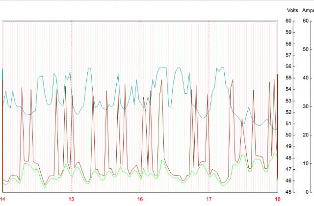 My home load includes 3 fridges and a few computers, two laser printers, 55" LED TV ... The startup of a fridge motor is clearly a significant event. I join the values of peak current together but it's a mistake to think this is the continuous value of the current. I just look at the peak values. These occur prior to an increase in the average current, as expected - the motor starts, then runs for a little while. It seems to me a fridge needs about 30A to start then runs on as little as 2A I am almost sure I know why I blew the inverter boards 3 times. The answer will be posted in my other thread. wronger than a phone book full of wrong phone numbers |
||||
| Madness Guru Joined: 08/10/2011 Location: AustraliaPosts: 2498 |
That's a bit of tease, when will you post the next installment? How old is your fridge? sometimes the start capacitors fail or the compressor gets harder to turn over. A fridge compressor would usually be 1 amp or less, my big side by side is under the 1 amp. There are only 10 types of people in the world: those who understand binary, and those who don't. |
||||
| poida Guru Joined: 02/02/2017 Location: AustraliaPosts: 1392 |
Mad, I think the start cap is feeling ill. But I want to use this to try and get my wife to accept we have to dump it. wronger than a phone book full of wrong phone numbers |
||||
| Madness Guru Joined: 08/10/2011 Location: AustraliaPosts: 2498 |
Have you put a meter on it to measure its power consumption, if you wife is carbon conscious it might be the leverage you need. A modern fridge should be around 1 - 2 KWH per day. There are only 10 types of people in the world: those who understand binary, and those who don't. |
||||
oztules Guru Joined: 26/07/2007 Location: AustraliaPosts: 1686 |
Most of the fridges I have worked on have a PTC thermistor that is responsible for the real starting. The "start" caps are actually shorted out by the PTC at start up, and do not contribute very much at all to starting, they are used primarily for PFC. The most likely culprit for poor starting or erratic starting will be the ceramic tablet that is the PTC thermistor. These are held by fingers that can deteriorate or actually lose one finger, and then the contact is poor, and the start current is poor in that circumstance. Once the ceramic tablet is shot, the "start" cap will not have a hope of starting the unit, and will have to be upped to 50uf or more just to start the unit without the PTC surge.... then you have to work out how to turn the big cap off after starting it. The PTC will be around the 15ohms at 25 degrees, and open circuit a second later at high temp where it stays during running. It is parallel the cap, so at start it "shorts" the cap to a large extent, and the 3-5uf is not very useful as a starting torque through the start windings anyway. The ceramic tablet must cool before another start can be made... a minute or so, depending on the plastic insulation around the hot tablet. If restart is too soon, the start cap won't/cant start it on it's own... so the thermal overload will kick in, and then when it resets, the ceramic will be cold anyway, and the whole thing will work normally. Thats the most common ones in use, there are ones that do have a real start cap, but very rare over here. .........oztules Village idiot...or... just another hack out of his depth |
||||
| Warpspeed Guru Joined: 09/08/2007 Location: AustraliaPosts: 4406 |
[quote]These occur prior to an increase in the average current, as expected - the motor starts, then runs for a little while. It seems to me a fridge needs about 30A to start then runs on as little as 2A [/quote] I did some refrigerator data logging as part of a total energy reduction plan a while back and my figures were: Normal running power 127 watts (0.55A) which agreed with the rating plate data. Off standby power 0.5 watts. Automatic defrost, about ten minutes every 24 hrs, 375 watts (1.56A) Startup single half cycle surge 4Kw (17A rapidly decreasing to about 1A over one second). On/off duty cycle 19% at around mid winter, although the kitchen is heated. Daily power consumption 0.728 Kwh. That initial startup surge is a real ball buster for any inverter, especially if there are other loads running as well. Cheers, �Tony. |
||||
| poida Guru Joined: 02/02/2017 Location: AustraliaPosts: 1392 |
I appreciate the time and effort given to me in aid of fixing the fridge. Thanks heaps. I will probably have to get it going and the info re. PTC is handy. It's 18 years old so it's due for replacement with a more efficient unit. I had the energy meter on it years ago and it was the biggest user of energy in the house. (approx $40/month if memory serves) Just when this all happened we found ourselves in Melbourne Spring weather and you know what that means: cold as Winter, again. SO I got the Nectre wood heater going and put it's fan on. This sources power from the inverter too. About 1/2 hour later we have huge mains hum, everything dark. Thinking I'd blown the inverter I got to the system to see both the street power contact breaker open as well as the solar system's 240V CB open. And the inverter was happily chugging away. I reconnected inverter to house load (inc. heater fan) and massive hum again. After isolating the cause of shorted loads as the fan, I reconnected inverter. It still is running OK. I probably had DC current input well over 50A during the shorts. And it survived. It's fused at 80A. Again, I think these shorted load incidents would have killed the previous 3 iterations. With the fridge on the way out, maybe the motor stalled causing high loads which kill the previous designs... The inverter must be able to handle shorted outputs, for as long as it takes to blow DC input fuses or trip DC input CBs. Now, as to the reason why the 3 earlier iterations failed: wronger than a phone book full of wrong phone numbers |
||||
| Warpspeed Guru Joined: 09/08/2007 Location: AustraliaPosts: 4406 |
[quote]It's 18 years old so it's due for replacement with a more efficient unit.[/quote] That is the key right there. I replaced my 20++ year old refrigerator with a secondhand one that was still the current model, which saved quite a bit. That change just about halved my total daily power consumption. Modern appliances are just so much more power efficient than the old junk. Payback period for my almost new refrigerator worked out to be just over two years. Had a similar experience when I replaced my old washing machine with an F&P. It not only saved a lot of power, but it works better in every single way. Cheers, �Tony. |
||||
| Madness Guru Joined: 08/10/2011 Location: AustraliaPosts: 2498 |
I have stalled a 5KW AC compressor powered by my inverter and all that happened is the 20A CB popped. Normally if a fridge compressor is stalled is it will trip it's overload protection (which takes a little time to heat up) and restart when it resets. If you turn off a fridge that is running and turn it back on again immediately you will trigger this process. The compressor can't restart again against the gas pressure from when it was running. Do you remember how much power in KWH's that fridge actually consumed in a day? There are only 10 types of people in the world: those who understand binary, and those who don't. |
||||
| oztules Guru Joined: 26/07/2007 Location: AustraliaPosts: 1686 |
Mad, I have pretty much proved that not to be the reason. In fixing many fridges, I have tested this theory, as it is espoused all over the place. It appears to be a wives tale in all the ones I have fiddled with. it is ONLY the hot ceramic in the PTC that makes starting impossible. I have never had head pressure cause problems during start up... no matter how hard I tried to emulate the industry excuse. When the PTC is at start temp ( 25c), there will be twice the running torque at start up... with or without the caps. It is the resistance in the start winding and the current passed by the PTC that provides the turning torque at start. I have never been able to stall it because of head pressure if I short the PTC out at start if it is hot. I suspect plumbers are familiar with compressors, and maybe even PV=nRT, and so find a plumbing reason for the poor start, rather than understanding what the electrons are doing, and how the photons are reacting withing the motor. Their explanation sounds plausible, but I have not been able to replicate it.... jam a screw driver across the hot PTC and it will definitely start. High head pressure is just high head pressure, if you look at the compressor at cold start, it near jumps out of the mounting holes... there is an enormous amount of excess torque there to play with.... but it only lasts half a second or so... until the PTC heats up, then takes minutes to cool down enough to start properly again. If you manage to get a phase change happening in the cylinder itself, then that is a different problem altogether.... and not starting would be preferable. It is a happy coincidence ( designed for I expect) that this PTC system makes fast restart impossible, and so allows any liquid formed before the condenser to evaporate before any restart is possible. ..... more than coincidence I suspect. In bigger units they have time interlocks that stop fast restart.... 10hp three phase motors have torque to burn, so I suspect it is the liquid problem they are worried about. Maybe others have nailed it down to head pressures, but I just have not found that to be the case as yet. .........oztules Village idiot...or... just another hack out of his depth |
||||
renewableMark Guru Joined: 09/12/2017 Location: AustraliaPosts: 1678 |
(snipped from P2) OK I'm trying to understand all that, I'll tackle one bit at a time. How do you measure the 75hz across the secondary Cheers Caveman Mark Off grid eastern Melb |
||||
| Tinker Guru Joined: 07/11/2007 Location: AustraliaPosts: 1904 |
Hi Mark, time for you to read up on parallel resonance. I'm sure google will find you heaps of articles. Anyway, here is how I tested this: Toroid not connected to anything on the primary side. Secondary side connected to the capacitor (start with 1uF and arrange it so different caps can easily be swapped. I use my el cheapo audio sine wave oscillator, this goes down to well under 50Hz. Best to check its output wave & frequency on the oscilloscope. The voltage is not much but that does not matter. Connect that oscillator in parallel to the secondary winding/ capacitor. Connect your oscilloscope there as well. Slowly increase oscillator frequency (from < 50Hz)and carefully watch the sine wave *amplitude* on the screen. This will increase at the point of resonance. Its not easily seen (at least with my testing). Note at what frequency that resonance peak occurred. Just to recap, the sine wave shown on your CRO increases its peak value as if by magic, without you touching the oscillators output level knob. Try again with more capacitance until you get the peak amplitude (resonance) at 75 Hz. Done, note what capacitor size did that. Double check by inserting a still bigger capacitor (don't touch oscillator knobs), the resonant peak should lower again as it now oscillates on a different frequency. As I said above, you need to understand how resonance works to test that. have fun. Klaus |
||||
| renewableMark Guru Joined: 09/12/2017 Location: AustraliaPosts: 1678 |
Thanks Klaus, I spoke to Tony/Warpspeed and he is going to test my setup for me. Cheers mate Cheers Caveman Mark Off grid eastern Melb |
||||
