Posted: 01:46am
13 Apr 2026
 Copy link to clipboard Copy link to clipboard |
Godoh
Guru

|
|
|
Hi Bryan, the connections can take a while to work out.
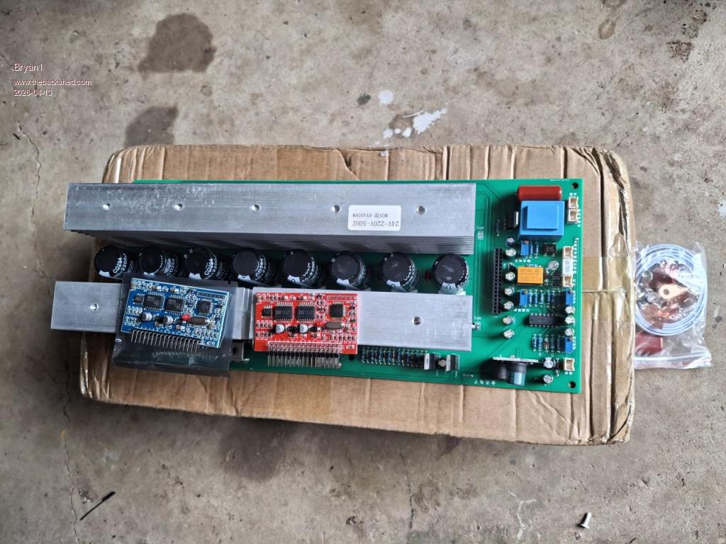
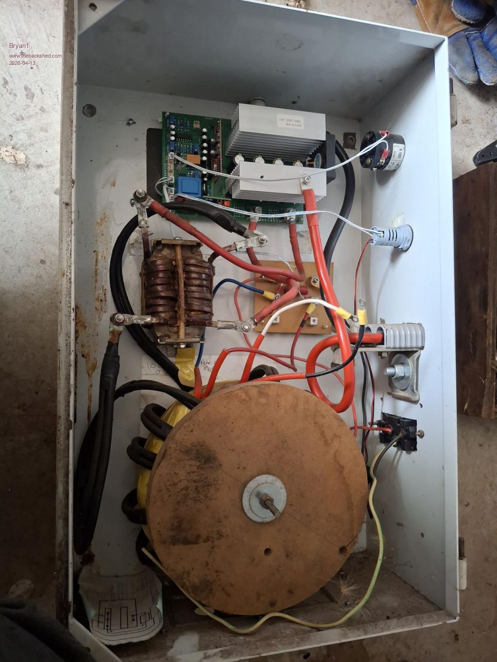
Near the transformer one of the sockets is for feedback, so if you have a look at which socket goes straight to the transformer that should be the feedback one.
Another one is for the LED to show the inverters state, either On or Standby.
The next set of sockets to the left will have one for the fan.
I will take some photos of my board and see if it is the same as yours.
Unfortunately they are a few different boards with different arrangements for the sockets.
If you can contact the seller of the board they can usually supply a diagram to show how the connections are made.
I will post a picture of my inverter later
Pete |