| Menu | JAQForum Ver 19.10.27 |
| Menu | JAQForum Ver 19.10.27 |
Forum Index : Electronics : MPPT Charge Controller built
| Page 1 of 2 |
||||||
First of all, Thanks to Poida, wiseguy, nickskethisniks and all others that contributed to this project.  Its been fun building this out of bits and pieces that have been scrounged from other things that most likely would have have been thrown out people that are supposed to be Normal.  Had a bit of trouble a few days back, it would do sweep and send a short pulse of power out to the battery and then stay in night mode, on some occasions it would go into MPPT mode but no output, Spent a bit of time to work out, and found a dud TLP250 driver. Looking at the rest of them in the pack, some of them had the pin 1 indicator and some didn't, so swapped it for one that looked more genuine and now its working.  Inside, neatness has evaded me on this one, but its not too messy, the perspex inductor clamp is over size in case I needed a bigger inductor later, the holes at the bottom of the box are filled in with 3D printed plugs, the LCD mount is 3D printed. 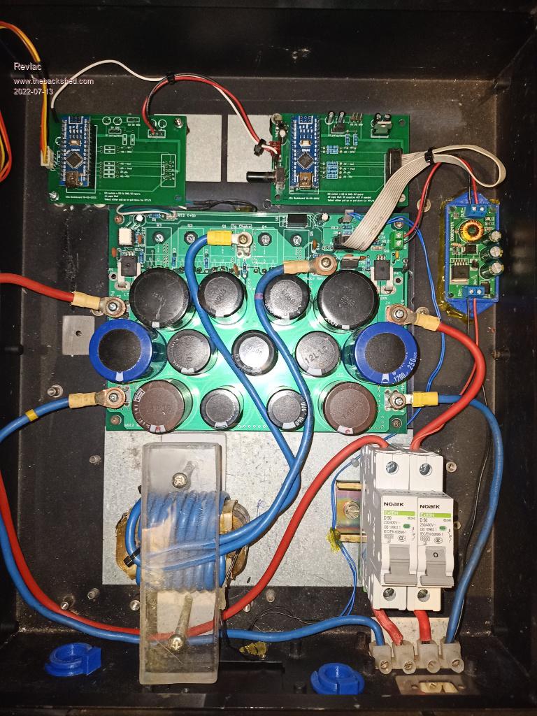 The box is an old Grid tie inverter, cleaned off the horrible paint from the cover and was going to repaint it, but the stainless steal was good, so why not try a brushed SS look, and put a clear coat over that, it turned out alright. The LCD Face panel is also 3D printed......Because I can. 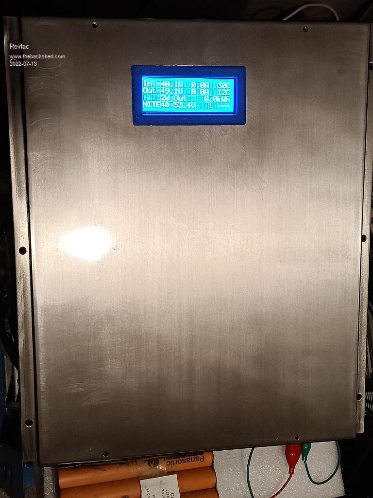 Had it connected to 4 car batteries and a pair of 250w panels today for its test run, I let it run the rest of the day and it went well. I noticed I have the temperature set incorrectly but will fix that, It needs the pull up in the menu. 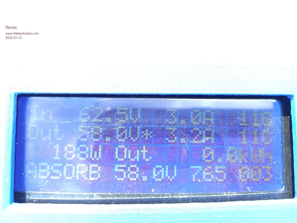 And the menu, these are the settings so far. 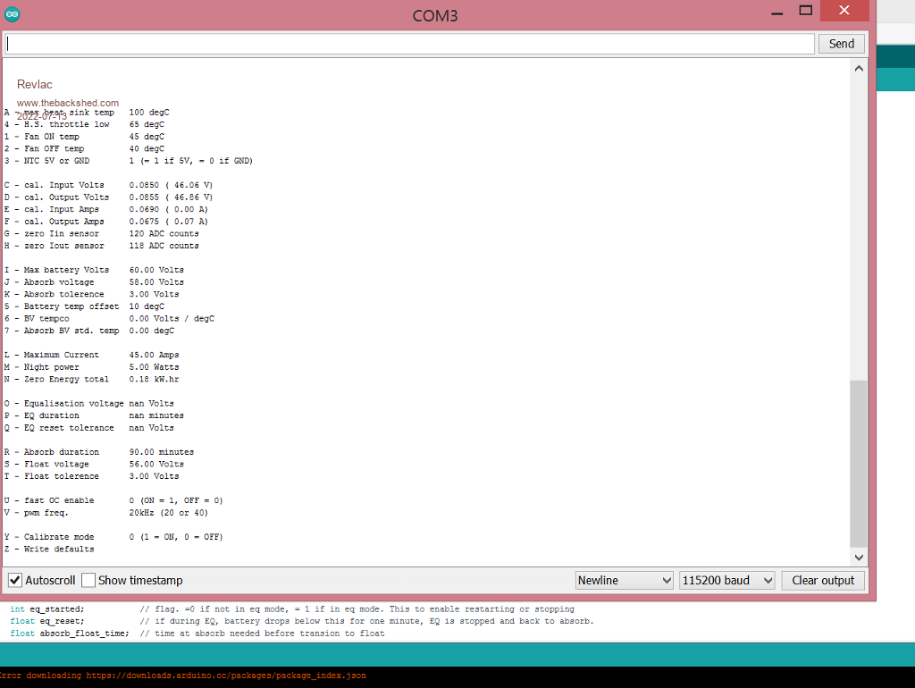 Later it will get a good workout connected to the set batteries and it own set of solar panels in the shed. Will take a photo of that setup at a later stage, its been fun working on this. Cheers Aaron Off The Grid |
||||||
this pleases me to a very large degree. Andy wants me to add an extra thing, being a measure of the day's energy. As it stands it shows the total energy and that's that. Stay tuned for a small upgrade to have it show the total energy for 10 seconds then the day's energy for 10 seconds. Should not be to hard to do. But getting back to you Revlac, that is a good build, using junk that we probably have lying around plus a few bits from RS. I look forward to Summer when you will see it work hard and just do it's job well. I notice the LCD showed it was in ABSORB mode so it had more than enough solar to get to the ABSORB voltage. Don't forget the firmware will throttle back the power when the heatsink starts getting too hot. You have settings that will start to throttle the power at 65C and bring it to zero power at 100C. That's probably going to be fine. It's funny (in my view) that I worried about fans for the heatsink when all I needed was this temperature throttle thing. It self regulates in a safe way if you choose "A" and "4" menu values correctly. finally, with those long wires for the LCD data then to the LCD itself you might find it locks up under big power conditions. The fix is to put some inline cable chokes on those wire bundles (these are commonly found on old laptop PS, VGA cables for PCs, lots of things) |
||||||
The BV tempco and ABSORB BV STD temp are two values you can use to adjust the ABSORB voltage as a function of battery temperature. I do not need a sensor on the choke, I believe they feel no pain so they don't need it. I put that sensor on a battery terminal. Now I can apply the temperature dependent ABSORB voltage curve to the mppt charge system. TO use it, you get the manufacturer's tempco. For my batteries it's -5mV/C per cell 48V means 24 cells so it's -5 x 24 = -0.120V /DegC at 25C it's zero correction so we set "7" = 25 and "6" = -0.120 and let it rip. When the battery gets hotter than 25C the ABSORB voltage will be trimmed back by -0.120 x (temperature - 25) And when the battery gets colder than 25 then ABSORB voltage gets a bit bigger. anyway, maybe you don't need it. But it's there for anyone who might want it. |
||||||
very nice! |
||||||
Thanks Peter, the 100c temperature, I was going to change that to 80, but not sure it the NTC is reading correct just yet I think it was reading a little over temp, will have a look soon. Ok I can run that Temp sensor to the battery box.  The BV tempco, depending on which battery I put it on either Li-ion or the the Lifepo4 battery, the Lifepo4 want the charge current lowered when batteries are cold bellow 5 or 10 degrees Celsius? will have to check that, for the batteries on the house I just use north facing solar array and that will lower the input current, seems opposite to FLA. So I should lower the charge current when cold, wont matter with a larger battery though. Perhaps I should have a little insulation for the battery box. Thanks CaptainBoing, Hope to inspire some more home brew builds. |
||||||
Nice build Aaron, good to see another MPPT joining the rank. I'm a bit concerned though that you used acrylic to clamp your choke. Now, acrylic softens & deforms when it gets warm and that choke *will* get hot. Why not have a look at the various methods (home made) I used to clamp the choke together? choke The first picture shows a few of my early chokes, I now use 2mm alu ends only, as shown on 2 of the chokes. BTW, I set my fan to come on at 50 degrees, off at 45, using an external fan controller (not the nano) for that. My enclosure is much smaller than yours so I'm weary of things getting too hot inside. |
||||||
Good job Aaron, looks plenty neat enough for its task. Great to see recycled bits used like this (as intended) and saving lots of dough on a bought one. Build & capacitor placing is rather symmetrical - all very arty ! Edited 2022-07-15 13:10 by wiseguy |
||||||
I have a pair of chokes from the 5Kw Aurora GTI, They are slightly larger size than the Aerosharp chokes. 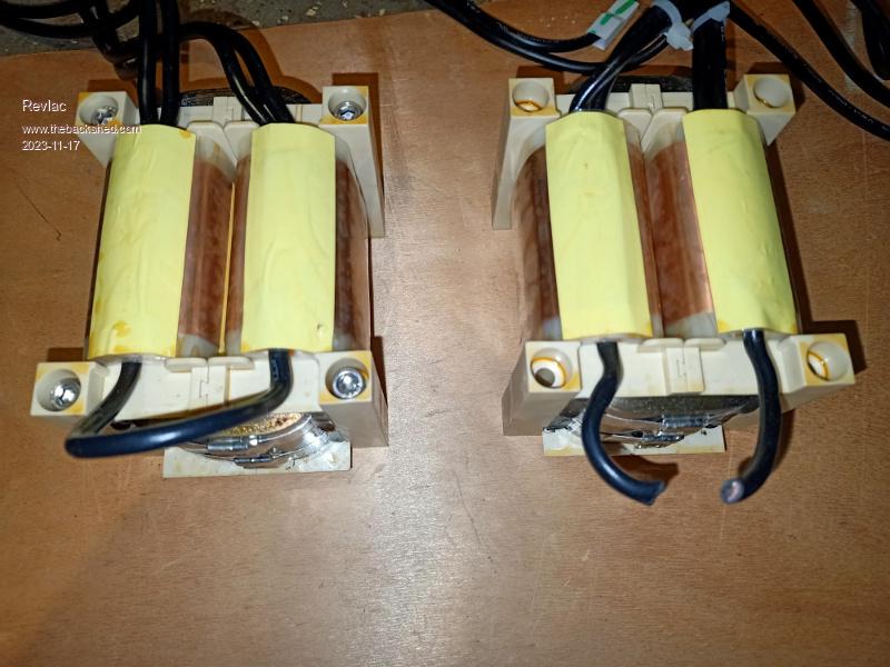 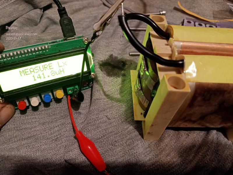 After cutting the wire between the 2 coils I measured the value of 140uH, (will parallel the 2 sides) seems to be close to what we want for this charge controller, will have to build and test it to see how well it works, its in a nice plastic mount and no rewinding needed if it works. |
||||||
They look interesting, are they wound in copper foil? |
||||||
Yep, Clean copper foil from what I can see, hope no one asks how many turns are on it,  very difficult to count the layers. very difficult to count the layers. |
||||||
Looking good :) always nice to see another one join the club. That would be good: when i was modding my version for the VFD display i decided I'd like a running total for the day, so i did a day total adding the current power every 1 second and reformatted the 3rd line of the display to show todays total with a few extra decimal places so i could see it increasing by the second. It still shows the overall total on the 7 day totals display. Trouble is my attempt isn't very accurate as it falls behind slightly during the mppt scan, and ends up slightly lower than your actual daily total. I look forward to seeing your new version. |
||||||
latest version for serial LCD with the hourly calibration of zero points for the current sensors plus the 6 previous daily totals? it's here mpptv5_BV_tempco_day_totals_current_sense_recal.zip you pull D2 down to ground to see the week's worth of totals let it float up and you see the usual display. need to hit the menu to zero the daily totals since they initialise as NAN. That is not useful. But we can zero them tho. by the way, great to see you making a CC. Do not feel for them, they do not register pain so we can start at 45 Amps max current but let it rip or 50 or 60A if you have the spare parts available. |
||||||
Ok, a little update, something I didn't notice in testing was that I was burning up the snubbers, R9 and R10 have scorch marks, I saw a little mark on them a while back and didn't realise what was going on, the other day I fired it up and I could smell them burning.  Its got me buggered what is causing this, everything else checks out ok as far as I can tell, the resisters are 10R on the diagram and the capacitors (c18 and C19) are 104 ceramic. Checked one of the 104 capacitors and it was a dead short it also took out the resistor with it so thats one problem, just don't know why. When removing the cap (with HOT soldering iron) most of the resin burnt out of the ceramic capacitor, so will replace them with something a bit more robust. 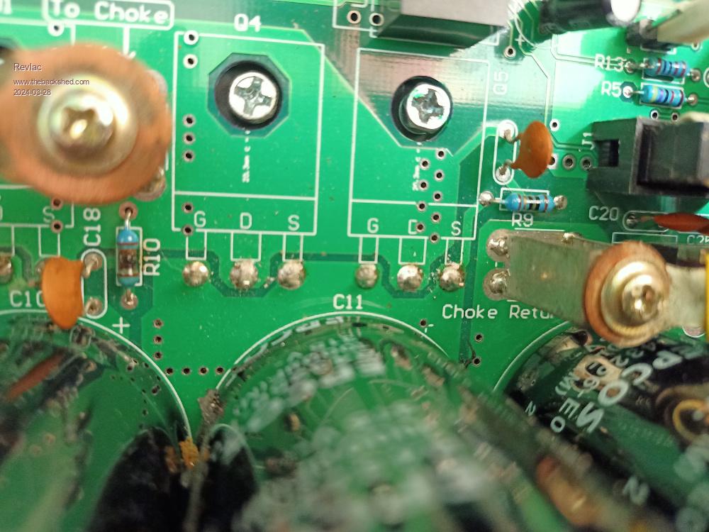 |
||||||
I usually see at least 1-2W resistors in RC snubbers. What was the voltage of ceramic capacitors? Isn't 100nF too much? in the original diagram there is 1nF. Edited 2024-03-28 19:01 by -dex- |
||||||
If you do need snubbers on a buck power supply then 1W resistors and a Polypropylene cap 250-400v would be a better preposition (PP are self healing). Must admit in all the PV charger controllers I've built to date, have not needed them. Best to run it at a lower voltage and look with a scope, you may not need them. Cheers Mike |
||||||
Snubbers burning out can be a symptom of RF oscillation. In other TBS threads ferrite beads on the drain legs and low value resistors between the gate legs and PCB have been used to good effect. |
||||||
Thanks for all the input, totally makes sense, I will try the ferite beads on one of the next MPPT builds and try it at low voltage and check for any voltage spikes, this build is working and I'm a bit hesitant to go probing in there and stuff something up, (done such a thing before) then have to repair it. The snubbers, I put a new little blue capacitor (type unknown ATM) and a 2w 47R resistor in place of C19 and R9, powered up everything no heat no problems, then replaced R10 with a 2w 47r, and left the original capacitor in place, powered up again, when power point tracking started the 2w resistor turned into a nice red hot glow so I have pretty much shorted that little capacitor, replaced it with a different new one and its running cool no no problem, this is probably trivial but I learn things this way. A few things to note, I did have the MPPT switching between bulk and float when the inverter was running some light irregular loads, so just increased the differential T float tolerance to about 6.00 volts, ow its good. The only little niggle at the moment is the MPPT will surge up to 60v very quickly after a large load is taken off the inverter, I have set the maximum to 58v, I sure the problem is my weak as piss FLA truck batteries, the other commercial charge controllers do the same thing on these batteries and often throw the over voltage relay inside, this doesn't happen when the lithium batteries, they just take it while the Charge controller back's off. I will put in some over voltage protection, something that will give the circuit breaker a little push and turn off the solar input, anyway its going happily. |
||||||
Making a start on the next one, going to try the beads on the drains this time even though though thew other charge controller is working great. Do we need a full complement of capacitors? If not I can use the space to run the choke wires between the caps through that area, or I find some different capacitors that are not too high and can run the choke wires over the top of them just to make it easy with the limited space available. 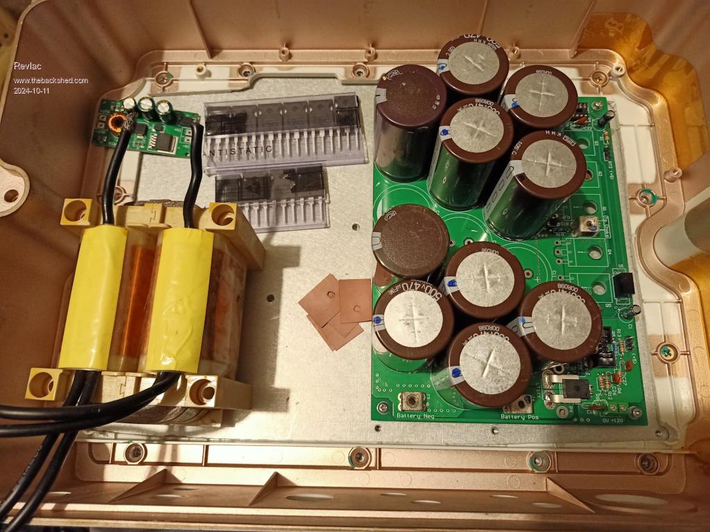 More later. |
||||||
Aaron Dex was right - I had not been following your build. The capacitors were supposed to be 1n and maybe experiment if you have a CRO values between 470P and 1n should tame the glitches/overshoot when the FET turns off. Larger capacitor is not better (it just makes the resistor hotter) I would use the smallest value of capacitor that gives acceptable results. If the top of the glitch is flat the FET is avalanching so the overshoot needs more capacitance to eliminate or reduce the avalanche to be non existent or at least very small. No wonder the 10R were smoking hot :). Where did you get the pretty yellow choke from - it looks like a foil winding ? |
||||||
Thanks Mike, Yes corrected, I now have 1n in this unit, I don't know how on earth I went with 100n in the other one, I printed out the diagram and 1n is now quite obvious. The choke is from a 5Kw Aurora Inverter, I might post some pictures of that later in another thread, lots of good parts in that. |
||||||
| Page 1 of 2 |
||||||
| The Back Shed's forum code is written, and hosted, in Australia. |

