| Menu | JAQForum Ver 26.09 |
| Menu | JAQForum Ver 26.09 |
Forum Index : Electronics : Wiseguy (WG) Inverter Build Discussions Australia
  Page 2 of 5 Page 2 of 5   |
||||||
Hi Jake, You're on the right track now, be encouraged. We're about to place our PCB orders in the next couple of weeks. Generally we've advised non Oz based builders to buy direct from PCB manufacturers, due to prohibitive shipping costs. However, we could consider it if you're willing to bear the expense. Also, Not sure where your WG build is at, but we are using the most current PCB version issued by Wiseguy about a month ago, so compatability would be a consideration. |
||||||
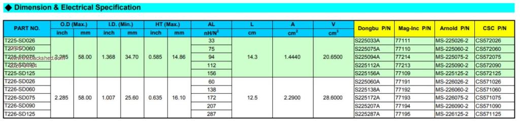
Just a short note on the sendust toroid cores for making the inductors. There are 2 suppliers outside of the China companies you should consider. Arnold/Micrometals making cores with the trade name of "Sendust". Magnetics making cores with the trade name of "Kool Mu" Both these types, have very similar performance and specifications. When I look at Aliexpress at the cores suggested above, I see a very different price than they are seeing in Australia. For 4 packs of 3 cores, I am seeing $30.18cad for each pack of 3 along with $22.94 cad shipping for all 12. So call it $11.97 each. If you buy 6+ sets of 3 you get an additional 2% off, so $11.73. If you look at the magnetics version of this core from Digikey, it is $11.44cad at quantity 10 and $9.57cad in quantities of 25.(you will be buying more that 25) So slightly cheaper and available locally with known good quality. Magnetics 0077192A7 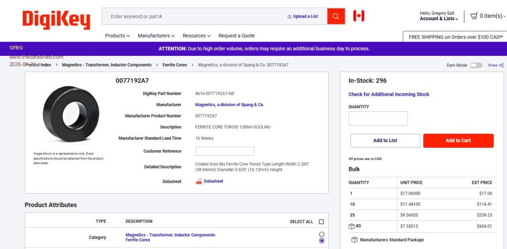 The distributor for Arnold/Micrometals (TME) does not currently have this core in stock, and I am not sure what their shipping costs are. Micrometals MS-226060 As always, YMMV but it is worth checking out standard suppliers with this type of thing. |
||||||
 |
||||||
Thus is how I wound my toroid primary. I did not use flexible welding cable. Instead I used 20 strands AWG #14 (20 x 2.0809 mm2 = 41.6 mm2.) It is more work, but I think It allows for more copper in the winding space and the copper wires get cooled better. It is a re-wound COTS 5 KVA transformer. The inverter it is used on has the following test results using stove heating elements for load: Load % Efficiency 1.8 KVA 95.7% 4 KVA 91.9% 6.8 KVA 86.9% 7.8 KVA 84.7% I used the same method for the choke. Just sharing. 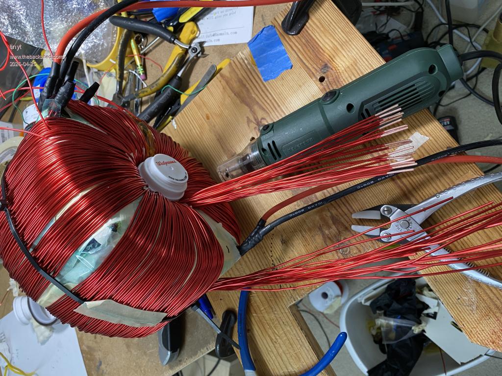 Edited 2026-04-25 03:21 by tinyt |
||||||
Thanks GleamBright, I will check the WG thread and think about it. I am using older versions of boards that's for sure. Thank you Greg for your help and a lot of useful information. I intend to research all these cores and their availability here in the UK this weekend  |
||||||
Thanks for sharing, tinyt. If I was to wind mine now I would consider doing it this way but I have mine wound exactly as per Ozinverter manual (welding cable) and I am definitely not re-doing it now if I dont have to after so much effort 😂. |
||||||
I scrapped a 5 kW Aurora inverter and found these transformer cores, they look amazingly similar to the required design specs. Is it ok to mix and match to come up with the required chokes? Since it falls slightly short of twelve of the black ones - am thinking to stack them as two sets of 4 x black + 2 x green. Black: 57x27x15 OD/ID/Width in mm, weight 182 g Quantity: 8 Green: 49x29x19, 123 g Quantity: 4 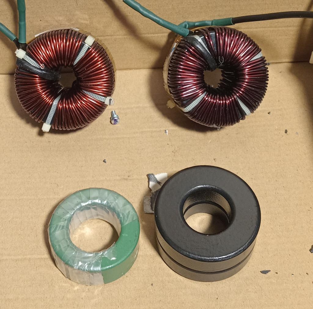 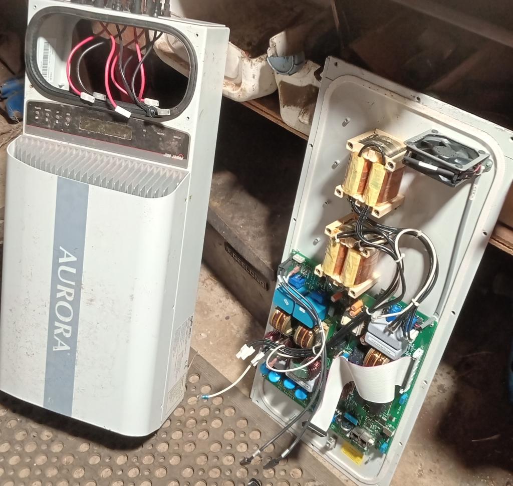 |
||||||
The black cores may be OK, most of the usable cores I've removed from old inverters have had a code number on the sides, if not, then the only way to know for sure is to use a Saturation tester to check them. Not knowing what test gear you have available makes it hard to suggest options, for example, if you have a way to measure the inductance of 4 cores with 6 turns of cable, it might give us an idea of the type of cores they are. But the black cores look promising, green would need to be checked, it usually indicates a different material mix. I have mixed cores to get the required inductance, so no problem, but the Mixed cores had "similar" saturation profiles and material mix. |
||||||
Could we also please get clarification on the minor queries in lines 2, 3, 4 & 6 in image below? From our working list for BOM '5KW FET Power PCB WG30Rev3 Issue 070225'.  |
||||||
2: likely 100v will have to check when I get home. 3: Yes 1n5 is 1.5nF 4: Tantalum or Solid. 6: Yes 5.1V They are written this way as the dot in 1.2k can be missed or faded, but 1k2 it cannot. Edit for item 4. . Edited 2026-05-16 12:17 by KeepIS |
||||||
I got blue cores from the 5K Aurora see here https://www.thebackshed.com/forum/ViewTopic.php?TID=10343&P=8 And those Copper sheet wound chokes are good for a charge controller no need to scrap them. |
||||||
KeepIS my instrumentation at the moment is only a multimeter, but I'll buy a basic LCR meter ASAP so as to measure inductance directly as I didn't get much info from an online search using the part numbers which are on the side of the black ones only. I'll be ahead overall by going this path with parts recovery from Aurora units rather than buying new from the Ali link you provided, and I need to learn this stuff along the way. Also intend to get a variable power supply unit for commissioning. Working on sourcing the BOM this week as a priority. Revlac thanks for the link, I read it and will also be keeping those wound chokes for a charge controller, not that I know what exactly to do with them just yet. |
||||||
My Charge controller Build here https://www.thebackshed.com/forum/ViewTopic.php?FID=4&TID=15007&LastEntry=Y#242833 So when you get your LCR meter you can test those chokes as well.  |
||||||
I'm not certain a basic LCR meter will give you saturation current, only Henries (mine doesn't, but it's several years old)? I think someone on here posted a design for their inductor saturation tester (trying to remember who...), which was much better than my cobbled together setup, and is used in conjunction with an oscilloscope. You don't need an expensive 'scope, a cheap pocket one will do, but it may well be worth getting a 'scope of some sort for testing I did get some good blue cores out of a Solis inverter, but couldn't read the part no's . Usually the sendust ones we want are blue or black. The green is more usually used for line filters on the d.c. inputs or 50Hz ac outputs and likely would not be suitable. |
||||||
|
||||||
that's the one i was thinking of!Such a simple, elegant circuit. Well worth building if you're planning to make inductors for inverters or mppt controllers. |
||||||
You can actually use the inverter powerboard itself as saturation tester, just reprogram the arduino nano to produce some pulses and connect the inductor on the h-bridge output(instead of the transformer). Just add a current sensor to measure the inductor current and watch it on the oscilloscoop. Simple as that.  |
||||||
Obviously an LCR won't indicate saturation BUT if 5 turns through 6 unknown cores give you around 17uH to 23uH then you likely have the correct material. I think you indicated that you are not at the point of building Saturation testers, etc. In any case, you also need a Digital Storage Oscilloscope [DSO] for that, some low cost units less then $200 out there, but that's for another day's discussion if you want. A variable supply capable of at least 3A at 60 volts would be ideal, they seem to be harder to get at the moment at 60V, but even a low cost unit at 0 to 3A at 0 to 30V would still be great for initial testing and setup. If you can post the numbers on the cores you found, I can go through the various numbers I have recorded for cores I have removed.  |
||||||
Would something like one of these work instead? 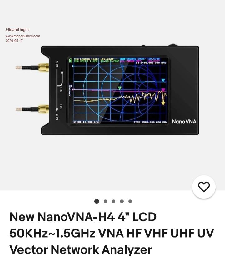 |
||||||
NanoVNA is good for many things but not for measuring power inductor saturation current. While LCR meters do not measure saturation current they can be used to measure inductance per turn. Just wrap 10 turns on the core then measure the inductance then divide by 10 using a basic LCR from Aliexpress. That should be adequate to tell whether the core is of the right type especially when you can reference known target values from other forum members' builds. The low saturation current cores typically have much higher inductance per turn compared to high saturation current cores (e.g. Sendust). Edited 2026-05-18 03:17 by analog8484 |
||||||
| Page 2 of 5 |
||||||
 |
The Back Shed's forum code is written, and hosted, in Australia. |