| Menu | JAQForum Ver 19.10.27 |
| Menu | JAQForum Ver 19.10.27 |
Forum Index : Electronics : Another Inverter Build
A few cores to play with, I tried 6 blue cores with 4 turns and the little test meter says 26uH, will try a few different configurations with the other ones, Actually 2 stacks side by side might be the go for the other cores. I might just add a silicon steel U core to go with it, see what pans out.  The Blue rings are MS-226125-2 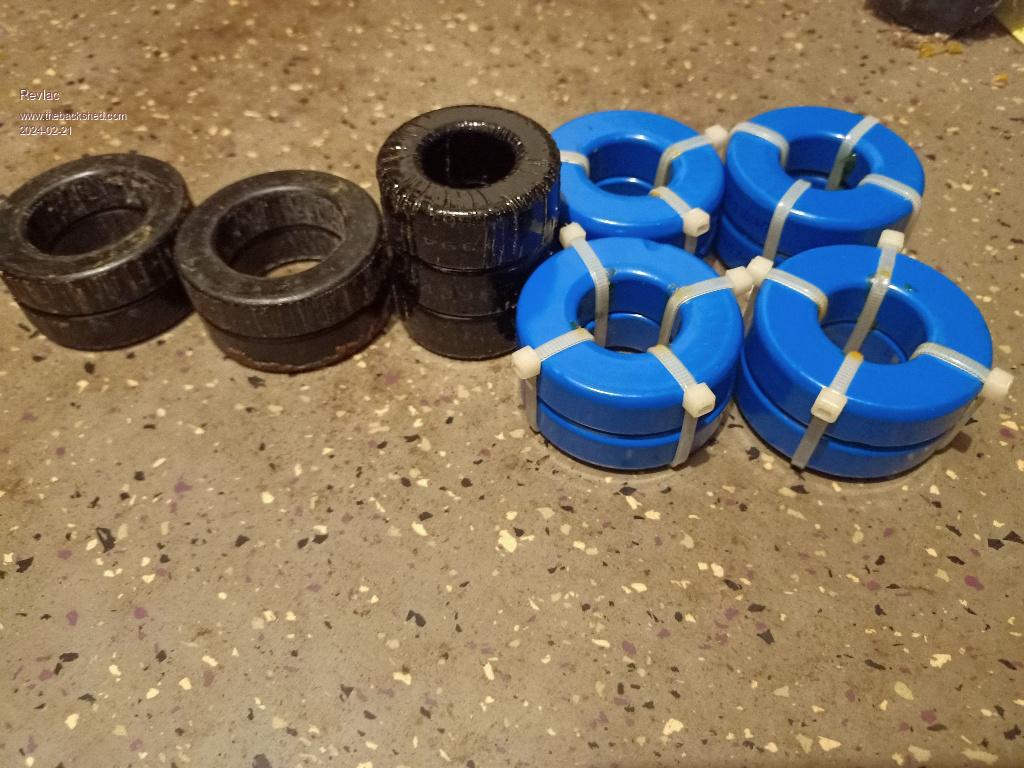 Edited 2024-02-21 23:28 by Revlac |
||||||
Hi Aaron, it is good to see the process of your build. Hope it all goes well with the cores Pete |
||||||
Gday Aaron, The black cores look like they were from a Latronics inverter ? But The blue ones I haven't seen before. Were they salvaged from a inverter and if so can you tell me what type - I am assuming they were probably from a TL, transformer-less model ? It appears the easiest and lowest cost method of getting those types of cores is from old scrapped inverters. Typically new cores like that are no less than ~12 - 15 AUD each or more, plus freight - unless you can find free shipping for 60+ dollar spends. Some inverters (later SMA's I think) use their own choke method where they seem to make and pot their own chokes in a batch of like cement impregnated with iron or ferrite particles and cannot be dismantled without a cold chisel and hammer and bye bye choke......  They are a bit like the old pot cores with 2 wires poking out the side but a heavy solid unit with a hole down the centre. They are a bit like the old pot cores with 2 wires poking out the side but a heavy solid unit with a hole down the centre. |
||||||
Aaron, those are the same Blue cores that I use in my chokes. I swapped some black cores (same size) into the chokes to get the inductance down to around 21uH each. Mike, I found the same thing with the later SMA inverters, I ended up throwing the pot cores in the bin. I wish I could remember what inverter the blue ones came out of, I ended up with 12 of them, the prices have really gone up, I want more   |
||||||
Blue Cores AliExpress Here , they are not new, but in good condition. The last item in their list 57.1x26.4x15.2mm specs: Model:MS226060-2 Outer diameter:57.1 mm Inner diameter:26.4 mm Height:15.2 mm Magnetic conductivity:60μ Inductance coefficient:138 nH/N2 Material:85% iron +6% aluminum+9% silicon Cheers Mike |
||||||
Those Blue cores are from a 5Kw Aurora GTI, If you can find one they are good for parts, eg they have parts that can help build 2 MPPT charge controllers or 1 MPPT charge controller and 1 inverter, or 2 inverters, so very useful, and I haven't tried the filter cores that are on the main PCB, more parts there, oh massive heatsink obviously. I could post a picture in the GTI parts section. but that might invite a mad rush for them? Correct, the black cores (still another one to unwind) are Latronics, the smaller black ones are from something else. Still haven't decided on the configuration yet. Even used ones cost a bit by the looks of. |
||||||
Mike, thanks for that link. Yes, getting expensive now. You are correct, now I remember. I was given an old Aurora GTI, the heat sink from that is on the back of my inverter, a massive beautiful heatsink, I think mine was a slightly smaller power unit.  EDIT- It appears that I have a mix of MS226060-2 and MS225060-2, had look at the 4 I have left and they are all MS226060-2, way back when I unwound the first stack, the first one from the stack was MS225060-2 - very hard to see on mine. FYI They are both the same dimension, I will go searching to see what I can find, but the value of inductance you measured appears to be about the same with these cores. Well, I went searching and it appears that the 6 looks like a 5 on some of mine, but they are definitely a MS226060-2 as the size does not match a 5. Getting old  Edited 2024-02-22 16:12 by KeepIS |
||||||
Thanks Mike, I thought my test meter might have been telling me lies as it was all over the place, turned out ok after running it a few times. Ok, I had an idea a few days ago and thought I would try it out, now with 4 turns this is about 21uH in this configuration, I would like this to work. This is also Fully adjustable by going through more or less rings so another quarter turn would give 25uH etc. I haven't seen this done before so wondering why and perhaps I have totally missed the reason why this shouldn't work, I can see if I go through another ring (quarter turn) that one would saturate before the others, Or go back out of the previous ring etc, any ideas? I can clamp this lot with a plate top and bottom and mount it on top of the main Toroidal transformer. 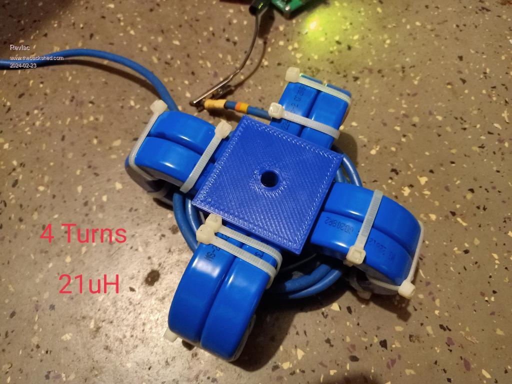 |
||||||
Similar concept here, last bit of last sentence. https://www.thebackshed.com/forum/ViewTopic.php?TID=15417&PID=197159#197159#197159 |
||||||
Great thanks. I remember that one now. |
||||||
Aaron you may already be aware of this. but I'll put it out there in any case. I would make sure to leave a clear air path through the Main toriod core, also allow for some air flow around the outer core in the design, as you may end up limiting the continuous running power of the inverter if you don't. And of course, I just know someone is going to jump on me for trying to simplify that. So YES, of course I know the final constant running power capability of an inverter is not calculated on something as simple as just the toriod running temperature. However, it's now relatively simple to build a High power inverter with respect to power stage design, choke design and correct cable layout and toriod winding. I assume anyone building an inverter from information on this forum has done that, or is on there way to doing that like yourself. So IMHO I would not want to be limited by temperature buildup inside the inverter case, and a big Toriod core is basically a huge "heat bank", especially in 40 plus deg temperatures. The Toriod transformer is without a doubt the main heat generator inside a "correctly" built inverter. The only Fans I have in the inverter are solely dedicated to keeping the Toriod windings and CORE cool, even in 43 deg HOT Humid temperatures, and even when running at high power for extended periods in those conditions. In my inverter, nothing else gets hot or needs forced cooling. |
||||||
In my country we have some of these blue cores available, but the prices are also high. There are also Sendust E-cores available from Micrometals at reasonable prices, I will describe this later in my topic. Edited 2024-02-23 18:36 by -dex- |
||||||
Just recently gutted out this 3Kw sunny roo GTI, Looks like a worthy enclosure for the WG inverter (placed inside), there is plenty room for the PCB's to be mounted with a display and switches on the front door, will hinge the door I guess, I may even use some of the output filter as it looks fairly strong. 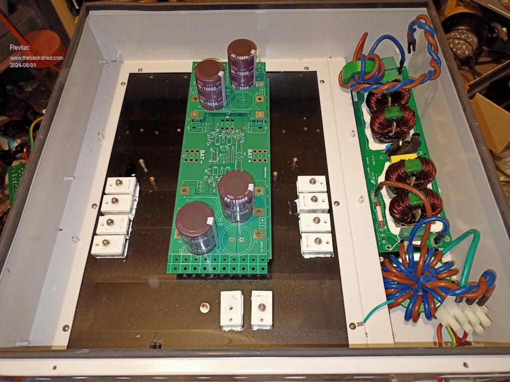 I don't seem to build 2 inverters the same so this one will have the 2 parallel Toroids mounted outside in a separate enclosure there isn't that many wires involved so I don't see a problem....YET. Still working on the current inverter build, just had so many other problems over the last month and haven't been able to do anything on this project, I thought things (life) would get back to normal but NO, normal is now quite different unfortunately sh*t happens. |
||||||
I know that feeling of different normal I'm not sure if you are building a Dual power board dual Toriod WG inverter, so apology if I'm off track: I'm also mounting two Toroids in two separate small cases, each with handles for easier lifting, I'm putting two chokes in with each toroid, so only SPWM drive cables and one AC lead connected to each case, the two ac output leads go to the AC control case. AC current trip and voltage sense will connect to the combined AC output lead in the AC control case. Keeps everything simple and neat with minimal interconnects. . |
||||||
Hi Mike, I hadn't intended to do a "Dual power board dual Toriod WG inverter" but thinking about keeping that option open for the time being, I do have 2 2Kw toroids that are wired identical...well almost, I need to add a few more primary turns to one of them. I was going to run them wired in parallel, will make sure the polarity etc when testing each one. I have to do a lot work in and around the house to make it more accessible (possibly wheel chair access)and easier for those that are older and not as mobile as I am, fortunately part of making things easier also includes this inverter to run the house and another as back up and easy to operate, change over etc. More details some other time. Sounds like you have yours pretty well worked out ......I only think I do, then end up changing something. |
||||||
It looks like I started a trend. It seems that many people are now open to dual power board dual toriod WG inverter design. I just think having that option is a brilliant idea opens up many options with power needs. A 12KW inverter can power up most homes large boats and campers and pretty much anything off grid. |
||||||
Making a little progress, placing parts on the big heatsink and making it all fit nicely can be a bit of a challenge depending on the amount of space available.  Thinking of using copper bar to link from the terminals to the power board etc, would would be better than messing with short cable and multiple crimped terminals that would cost more, still have to layout the output to the transformer and its good practice to test fit folding cardboard to the terminal layout before bending copper bar and stuffing it up, haven't stuffed any yet but there is still time for that. 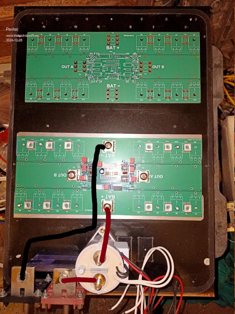 BTW, The box this all sits in is bigger than the heatsink, there is more room to use on the Right side, probably Mount the control board there, will see later. I already have a picture of the box.....forgot that. |
||||||
I have had success using multiple layers of copper sheet (0.6mm) cut into strips. It has much more flexibility than solid bar so perfection isn't required. Covered in heat shrink it looks as neat as bars. |
||||||
I found using short quality 2G cable with quality dual-crimp connectors resulted in no extra heat in both the single and dual inverter builds. Under high power, the PCB copper bus will get warmer than those large single PCB connectors using quality crimp connectors, same with the connections to the chokes. |
||||||
| The Back Shed's forum code is written, and hosted, in Australia. |

