Notice. New forum software under development. It's going to miss a few functions and look a bit ugly for a while, but I'm working on it full time now as the old forum was too unstable. Couple days, all good. If you notice any issues, please contact me.
phil99 Guru Joined: 11/02/2018 Location: AustraliaPosts: 1788
Posted: 11:35pm 30 Jan 2023
Copy link to clipboard
Print this post
A very impressive effort. The benefits of a complete rewind are too small for the work involved.
While you are still in the experimental phase, an idea to consider re series inductor:-
Extending the idea of getting some inductance by bunching the primary turns together you could then put a pair of C-cores around them for more inductance. Vary the amount by varying the gap and / or not putting the cores around all the turns.
wiseguy Guru Joined: 21/06/2018 Location: AustraliaPosts: 998
Posted: 03:58am 31 Jan 2023
Copy link to clipboard
Print this post
I obviously shouldn't post after 12.00pm at night.....The relatively few turns on the triple toroid momentarily tricked me into thinking it was 24V. Of course when you stack the cores the primary turns reduce accordingly.
I like phils suggestion a bit less lossy than a separate choke !If at first you dont succeed, I suggest you avoid sky diving.... Cheers Mike
Hi Mike, may I suggest using one of these inexpensive and efficient 1800W DC-DC boosters for charging your 48V Battery bank directly from your existing 24V solar array:
https://www.aliexpress.com/item/32883381658.html
I have been using one of these converters for over a year to charge a 24V battery bank from a 24V switchmode power supply that kept shutting down due to the low internal resistance/ high current demand from the battery and it has proven to be a very reliable CC/CV charger with the added feature of an adjustable low voltage input cutoff.
It should allow charging your battery bank at a rate of up to 22A/1250W per unit and you could run two or more in parallel using 0.1R 100W output load sharing resistors, if needed and if your solar array can provide sufficient current to run them.
BTW, I would not recommend buying the fanless 1200W version as it does need cooling at such high current levels.
Cheers.Cheers Michael
KeepIS Guru Joined: 13/10/2014 Location: AustraliaPosts: 1365
Posted: 04:33am 31 Jan 2023
Copy link to clipboard
Print this post
It still throws me sometimes looking at the primary, but now I just visualize the length of cable, and then it makes sense as obviously there's a few of meters of cable in there.
BTW: I only used 100A cable because the highest continuous usage will be under 2kW 80% of the time and never above 3kW except when starting those dam wood working machines. And the local price for heaver cable is stupid.
As you tell it's all of 5 minutes to rewind a heaver primary if needed, lots of room.
I also like phils idea. By the way phill thanks for the observations and drawing, I will try that along the way.
At the moment I like "some" resistance between the Toriod and the driver board, I think some of the blow ups might be due to 0 gauge primary and very heavy wound chokes under nasty load glitches.
The toriod choke: I just tested the Black version of the Blue toriods:
Both appear to be good to around 240A and then a slow rise to saturation. Just testng under Heavy loads to see if 30uH or 40uH is the go - the dual E-Core on the Hi side is 31uH. .It's all too hard. Mike.
KeepIS Guru Joined: 13/10/2014 Location: AustraliaPosts: 1365
Posted: 08:40am 31 Jan 2023
Copy link to clipboard
Print this post
Thanks for the info, I had been looking at one of those but I am planning to build something bigger in the next few months. However, at the price of the unit I decided to buy one to play with, I can see a lot of uses for this when I need a certain voltage to test something in a hurry.
In the mean time, I hope I feel good enough over the next few days to swap one set of old panels out to another position and put 4 x 400W new Panels that I have waiting to go in.
I have 4 x 12V to 48V Solar charge controllers, each one is capable of 60A at 48V if you feed them enough. Once I get the panels up and the panel wiring quickly rearranged from 24V to 48V, I will be set for testing with part of the battery bank (I'm currently using at 55V for this inverter testing) and part of the solar also running at 55V with a decent charge current for the testing. .It's all too hard. Mike.
I forgot to mention the power output estimate I gave for this unit was based on the assumption your 24V solar array can output at least 32V DC to the converter under load as the max. output power is limited by the available input voltage and max. current ratings, 40A Input/ 22A Output.
Of course, rewiring the panel array for 48V and using a proper solar charge controller is a much better option. My suggestion was only for a temporary alternative to your current 4A battery charger. Either way, these converters are very useful for quite a few applications and worth buying at least one at that price.
Provided you can fit enough panels on your roof, the four solar charge controllers will be capable of providing a substantial amount of power at 48V output so you should end up with a great system when it's all done.
I hope you'll feel better soon, take care.
Cheers MichaelCheers Michael
KeepIS Guru Joined: 13/10/2014 Location: AustraliaPosts: 1365
Posted: 10:39pm 31 Jan 2023
Copy link to clipboard
Print this post
Thanks.
Yes I read the specs so no problems, it will be used for lots of other things, just so handy to have.
Available solar power is around 10kW, there is another 1kW of old panels (soon to be 2.5kW) running the Hot water system, so fortunately the inverter doesn't have to carry that load. .It's all too hard. Mike.
KeepIS Guru Joined: 13/10/2014 Location: AustraliaPosts: 1365
Posted: 11:26pm 02 Feb 2023
Copy link to clipboard
Print this post
I've been looking for something to charge the temporary test setup of LiFePO4 48v batteries and was looking at using an old CIG welder:
Dumb, as I had no idea how hot those huge old style transformers setups in these arc welders get just doing nothing, and while it can supply a lot of current it needs a few extra turns to do it at a decent current for what I want.
But like a script for dumb and dumber, after trying that, one of the few remaining brain cells finally remembered that I had grabbed a hybrid Solar inverter at a bargain price when a friend was purchasing a big order of them, so I had grabbed one to replace the 14 year old solar river inverter when it finally dies.
It's an off grid GROWATT SPF 5000 ES, it takes 48V batteries, has 5kW/10kW AC inverter and a 100A Solar charger AND a 60A AC charger. Never even opened it to see if it works. Mind is going
Unpack it, find it fits nicely on a big cupboard next to my bench, 240AC connected and batteries connected, set it up for LiFePO4, I can set it to any charging current to what ever I want up to 60A, works perfectly.
I ran the test inverter with a 1.6kW load for over 5 hours. HI side heatsink was only warm to touch. I added a small fan to blow some air to keep caps cools as well, within a few seconds the heat sinks were cold and remained so.
The chokes were slightly warm. The Transformer toriod cores were virtually cold, the only warmth was from the primary windings, just a slight warmth when you placed your hand on them, no air flow at all around the transformer.
However with this number of loads connected (the whole workshop) the AC waveform was not the greatest, some flatting at the top and bottom, some of that from the big UPS inverter and other SMPS plug packs. There is an Inverter AirCon running, test gear and other small equipment in use through the day etc. But it ran fine apart from the waveform shape.
I was looking through some old posts but didn't see any pictures of the AC waveform when a lot of different loads are connected and running.
I'll post some pictures if anyone in interested before I start more testing later today.It's all too hard. Mike.
Revlac Guru Joined: 31/12/2016 Location: AustraliaPosts: 961
Posted: 12:23am 03 Feb 2023
Copy link to clipboard
Print this post
Thats almost the same as the one I have running the house, only yours has the Hi voltage solar input instead of the 120v MPPT, the rest of it is the same, although I have never tried the 240vac in for battery charging. Edited 2023-02-03 10:24 by RevlacCheers Aaron Off The Grid
KeepIS Guru Joined: 13/10/2014 Location: AustraliaPosts: 1365
Posted: 12:43am 03 Feb 2023
Copy link to clipboard
Print this post
I bought it for a simple drop in replacement for when the Solar feed in tariff gets cut or the Old inverter dies.
I can then just add more panels to the old existing 3kW house panels, add a 48V battery and it runs the rest of the house. Obviously no feed-in but I have a feeling that is going to disappear in the near future.
Just as a 240vac to 60A 48v-58v battery charger it really rocks.
Prices have gone up as well, I got mine for about 1/2 price when they were already at a very low price point. You might even pay more for just a battery charger now?
EDIT: The AC charger is actually 80A @ 48V
Cheers. . Edited 2023-02-03 14:57 by KeepISIt's all too hard. Mike.
Revlac Guru Joined: 31/12/2016 Location: AustraliaPosts: 961
Posted: 07:32am 03 Feb 2023
Copy link to clipboard
Print this post
80A is quite good, The 5048MS on the house is 60A utility charging and 80A solar charge, they can run at the same time. I take it the top Left hand side air vent is not very hot when run in AC charging mode?Cheers Aaron Off The Grid
KeepIS Guru Joined: 13/10/2014 Location: AustraliaPosts: 1365
Posted: 08:21am 03 Feb 2023
Copy link to clipboard
Print this post
When it's not charging it slightly warm, only charged at 40A so far, gets a little warmer at 40A, I like its 100A solar charge rate as well. . Edited 2023-02-04 11:44 by KeepISIt's all too hard. Mike.
KeepIS Guru Joined: 13/10/2014 Location: AustraliaPosts: 1365
Posted: 01:39am 06 Feb 2023
Copy link to clipboard
Print this post
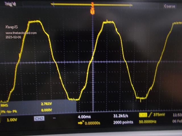
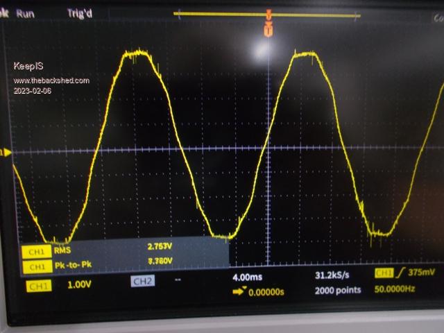
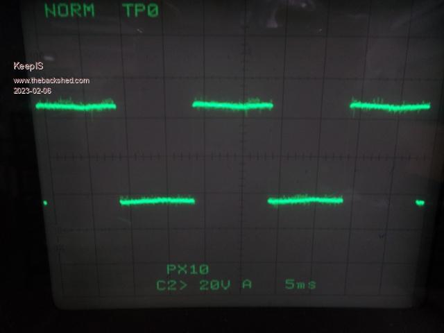
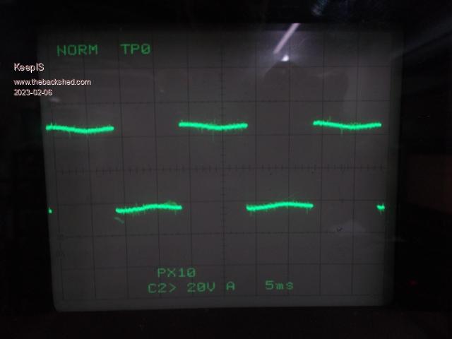
AC wave form under multiple loads:
The test inverter has been running the workshop, Inverter Air conditioner, 600w exhaust fan, computers, a few SMPS units, bit backup UPS for the computers all running and more.
(1) Normal Load is sitting at around 1.2kW
(2) Switch in another 1.8Kw for a total 3kW for 5 minutes at a time.
Tiny 55mm 12v fan sitting on the inverter board, no ducting blowing across the caps.
After continuous running time of 3.4 hours:
1: Hi side heatsink runs from cold to barely warm, barley warm being 3kW.
A: The only sound is from the E-Core choke B: Toriod choke is silent C: The 3 stack Toriod Transformer cores are cold and silent.
NOTE: At almost 14kW startup, the AC waveforms are NOT flattened on top or bottom.
The 3kW AC is rounder than the 1.2kW AC waveform.
Waveforms: Thoughts ?
1.2kW load.
3kW load.
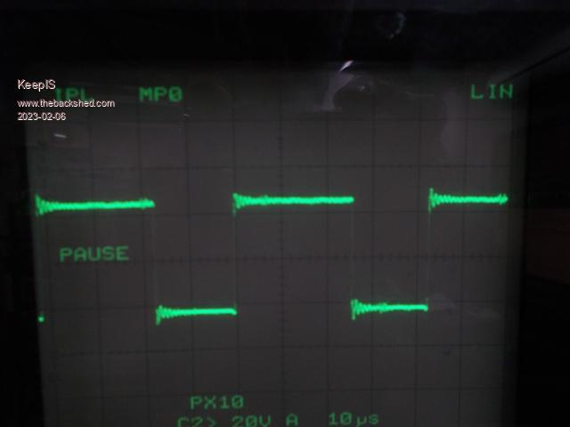
1kW HI side.
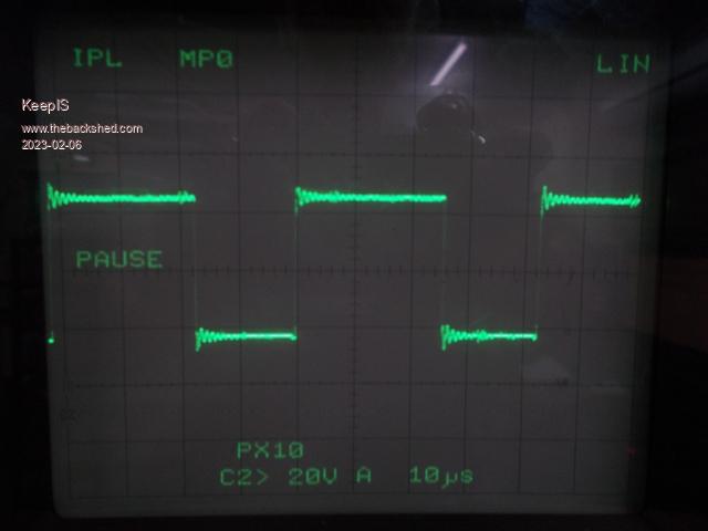
3kW HI side.
1kW LO side
3kW LO side . Edited 2023-02-06 11:41 by KeepISIt's all too hard. Mike.
wiseguy Guru Joined: 21/06/2018 Location: AustraliaPosts: 998
Posted: 01:49am 06 Feb 2023
Copy link to clipboard
Print this post
Thoughts ? I reckon stop probing & poking around and put it in a box with a lid on it before you slip with a probe and it goes bang lol. I don't think you could improve it much more.
It looks like it is a totally bullet-proof inverter with quite good looking waveforms considering the various loads, and it also appears the higher the load the better the waveshape, congratulations - job well done !If at first you dont succeed, I suggest you avoid sky diving.... Cheers Mike
KeepIS Guru Joined: 13/10/2014 Location: AustraliaPosts: 1365
Posted: 02:10am 06 Feb 2023
Copy link to clipboard
Print this post
Thanks mike, I think I just needed to have a second opinion, thanks for that.
Will soon start on the fun part, building a new inverter board to drive the transformer. It will be nice to have backup for when I switch across to a complete 48V system.
It's currently idling at around 600 watts and the efficiency works out to 93%. But at these low loads I would not put to much into that. I'll test at 3kW later on, that should make the margin for error a bit less.
Cheers. .It's all too hard. Mike.
KeepIS Guru Joined: 13/10/2014 Location: AustraliaPosts: 1365
Posted: 06:16am 06 Feb 2023
Copy link to clipboard
Print this post
The last test was to start the Bandsaw which draws 255A start current and test if the Air conditioner cuts cooling for a few seconds and test if the Computer UPS beeps for any reason, very touchy fast acting UPS.
With the workshop running on the inverter the Bandsaw was powered up.
1: Transformer hardly makes a noise, just the E-Core choke buzzes for a second or so. 2: Aircon remains on full cold air blast. 3: UPS not a beep.
Total current drawn including test equipment other workshop gear, Aircon and Bandsaw start up:
267A DC input, just under 14kW.
Efficiency at a 1.6kw load comes out at 89%, but it's hard to get the meters to stop hunting the last digit with the test layout, the lead connecting the Workshop to the inverter for testing is only rated at 10A. So the next step is to get the transformer and backup interface done correctly as I think the transformer will do everything I need. I can the then swap inverter drive boards easily for the next phase in the build. . Edited 2023-02-06 16:17 by KeepISIt's all too hard. Mike.
KeepIS Guru Joined: 13/10/2014 Location: AustraliaPosts: 1365
Posted: 09:22am 20 Feb 2023
Copy link to clipboard
Print this post
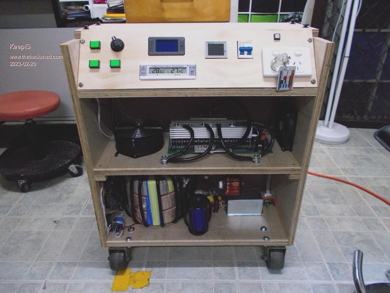
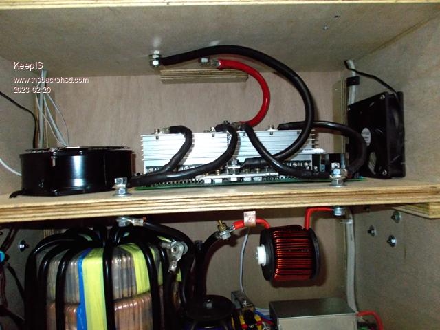
After going over all options, I decided to build a Cabinet for the Inverter out of 18mm Marine Ply.
I have used this for many large electronic builds over the years, if you don't know how to protect high current equipment then maybe it's not for you, I don't have a problem using it. I have found over many years of RF work that a metal cabinet does not automatically lead to low spurious radiation. It's a lot more complex that that.
The advantages of marine ply are a very dense material leading to high sound and vibrations insulation. The Inverter running at 3kW is silent -- I mean silent!
The airflow is through a filter and inlet fan on the right hand side of the middle compartment.
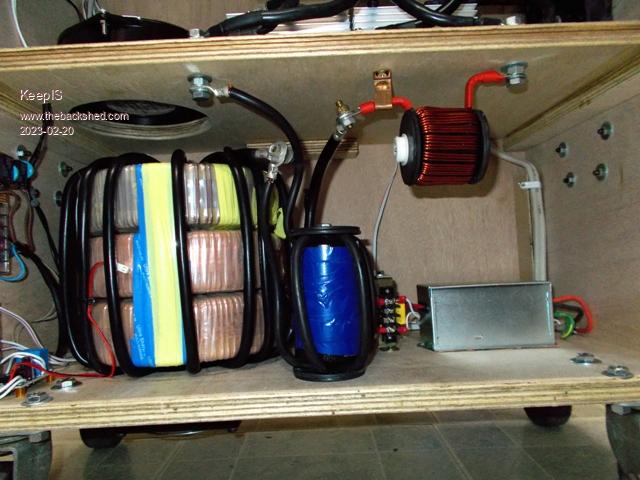
The outlet is from the bottom of the Toriod stack through the bottom of the lower compartment.
The inlet fan is a 120mm silent fan, it runs from an auxiliary 240vac to 12vdc supply.
A second fan at the other end (LH side) of the inverter driver compartment is a large 150mm 240vac fan, it's switched via a relay driven by the over temperature Fan output of the inverter driver board. This second fan moves a lot of air and is very quite inside the sealed enclosure, it sucks air in through the silent fan inlet and drives air down into the lower Toriod compartment and through and around the toriod.
A 3rd fan is mounted on the bottom of the cabinet below the toriod, the fan is controlled by the toriod core temperature, it sucks air through and around the toriod as the hole below the toriod is 150mm diameter and the center of the toriod is completely open. I seriously doubt it will ever run.
The back and front panels are held on by finger tight 8mm raised bolts. These are hand tightened and screw into steel nut inserts. So complete access is available to work on the unit. The center shelf is removable, again using steel screw inserts.
The inverter module can be removed without disturbing any of the cabling in the Toriod and dual choke compartment. Conversely the Chokes can be modified or replaced without touching anything in the Inverter drive compartment.
Th HI and LOW connections along with the DC input are via threaded bolt connections between compartments.
The top cover, behind the sloping front panel is removable (4 screw inserts) and gives access to the Battery connection terminals and main AC connection block.
There are no connections behind the unit and nothing to move to get access to all connections.
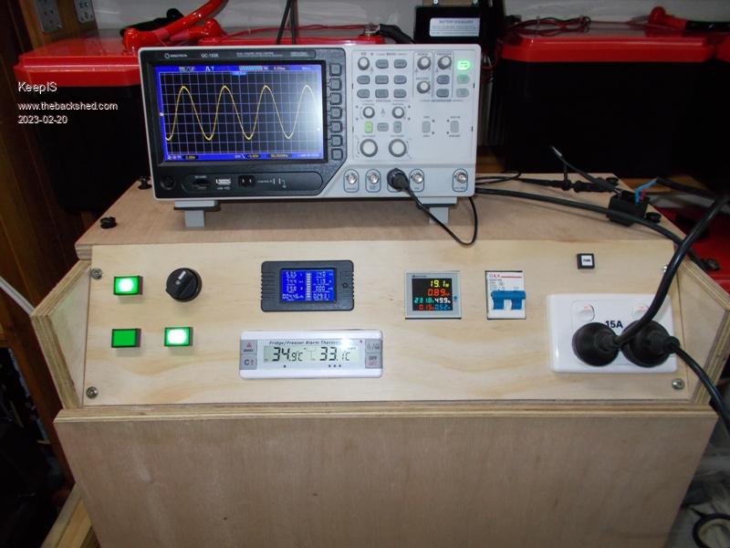
There is a dual 15A socket on the front panel for testing and local connections.
Large heavy duty wheels make moving simple.
I've had this running all day connected to house and shed, it runs cold. The only time you can hear anything is when the stupid heat gun is on low with that bastardized waveform from a diode in series with one side of the mains.
Another day of running and testing before I convert the rest of the solar system over to 55V.
Front panel removed.
Note: Front panels and case have to be rounded over, finished and sealed.
With just the Silent inlet fan running, the air exiting the bottom of the cabinet is quite strong. The airflow path has proved to be very efficient. Edited 2023-02-20 19:34 by KeepISIt's all too hard. Mike.
Revlac Guru Joined: 31/12/2016 Location: AustraliaPosts: 961
Posted: 09:45am 20 Feb 2023
Copy link to clipboard
Print this post
Looks Great, well done. I think I have some of those 120mm fans in 24v.Cheers Aaron Off The Grid
Murphy's friend Guru Joined: 04/10/2019 Location: AustraliaPosts: 583
Posted: 03:31pm 20 Feb 2023
Copy link to clipboard
Print this post
I see you were having fun building this, how big is it?
3 fans?, well my first inverter required 4 . Reason, the cabinet was way too crammed.
But all the other inverters I built since have now only one fan in the cabinet. It blows air upwards, from a screened inlet at the bottom to an outlet at the top side. That fan only cycles when ambient temperatures in my workshop are over 35 degrees when the load is high.
Now you need to build another inverter from scratch . None of that hot running Chinese gear, Anyway, welcome to the inverter builder club, you are one of the very few who got it going without a bang, or did you?
KeepIS Guru Joined: 13/10/2014 Location: AustraliaPosts: 1365
Posted: 10:24pm 20 Feb 2023
Copy link to clipboard
Print this post
Thanks, the 120mm Silent fan is 12v, noise is 20dba, basically I can't hear it. The other two are 240vac.
No I have not blown a single component, I have let the smoke out of a few cables and a CRO probe earth though. You know that just jinxed me
I wanted plenty of room around each section to make modifications, fault finding and upgrades simple.
The Cabinet is 600mm x 600mm x 300mm deep.
I gave up on drawing air from below after years of working on dust covered internals of equipment, even with filters, which end up being out of sight out of mind.
The extra two fans can also be run in series and make for an almost silent higher airflow path. The toriod transformer in this inverter is capable of easily running at 5kW for extended periods, so the extra cooling fans are for those humid 38 deg summer heat wave conditions with multiple air conditioners and fridge freezers running.
I have everything ready to build my own inverter driver. That's why it was important to make the Cabinet and inverter driver compartment as fool proof as possible when changing driver boards, no chance of disturbing and wiring in the rest of the inverter, I already have the current sensor installed ready for the new driver board.
Surprisingly this Chinese inverter runs almost cold, I have separate temperature sensors feeding the front panel readouts, one in the Toriod Core and one in the HI side heatsink just above the FETS (the warmest spot I could find)
It was 31 deg yesterday and the HI side only got to 34 deg @ 1.7kW after a few hours. The Toriod core was basically air temperature + 1 deg, only the silent fan running, most likely the heat from the exhaust air flow cause the toriod felt cold.
Idle power is 17.6 watts. The 240V -> 12v Aux supply for the Silent Fan and temperature sensor control board consumes a total of 4.2 watts, so the total no "external" load power is 21.8 watts. . Edited 2023-02-21 08:25 by KeepISIt's all too hard. Mike.


 . Reason, the cabinet was way too crammed.
 . None of that hot running Chinese gear,