| Menu | JAQForum Ver 19.10.27 |
| Menu | JAQForum Ver 19.10.27 |
Forum Index : Electronics : Turning a Toyota Prius into a "portable" generator
It sounds like you now have several different problems to solve, and the only way forward is to check through every single thing starting with just the bare control board by itself. Check every pin on every IC with an oscilloscope. There should be either ground or +5v, and clean rail to rail switching waveforms everywhere. Any "funny" logic levels means electrostatic damage. Make sure the analog to digital converter is working properly, or just replace it (for the time being). All four power stages are functionally identical. All four transformers can be driven with any of the four waveforms as they were all designed to accept 230v 50Hz ac on the primaries. Verify all the gate drivers and gate driver power supplies are functional. For initial testing just use only the drive waveform for the largest inverter. Its a simple 50Hz square wave, very easy to see on an oscilloscope, and very easy to trigger onto. Plug that into each power stage one at a time, and make sure all your mosfets are switching properly. Even the smallest power stage and smallest transformer will run off that basic slow 50Hz square wave, its a lot easier to see exactly what is going on with such a slow simple repetitive waveform. As with repairing ANY inverter, you need to clear ALL the various faults before powering it back up, or it will just keep going bang all over again. The Warpverter has one big advantage, modularity. If one inverter dies, there is no simple way for that destruction to propagate back to the driver board, or other power stages. If a pwm inverter fails, the whole lot usually self destructs in a spectacular way. The exception to that might be a fault on the driver board, but if you check the digital signals on every pin of every chip, either the logic levels will be partial, or not there at all. There are not that many chips on the board, should not take long to check every pin against the schematic. I have seen "funny" logic levels on a perfectly functional board. Electrostatic damage may be partial not total. But it could lead to future grief. |
||||||
Thanks warpspeed. Does that oscilloscope trace correspond to more-or-less what I should see for the second largest inverter output? Also is 10nf correct for the dead time capacitors? |
||||||
Any of the four inverters will look the same when driven with the drive waveform for the largest inverter. ----------------- . . . . . . -------- ------- ------ . . . . . . --------------- Yes 10nF will be plenty of dead time, that is what I am using. Its now three years since I looked at any of this, but from memory that was around 2.5uS which is heaps. 1nF was about 300nS dead time, and no capacitor at all about 50nS of dead time. Edited 2021-01-11 17:37 by Warpspeed |
||||||
The image I posted was of the second largest inverter. Does it look right? |
||||||
 Yes that looks fine to me for inverter number two. 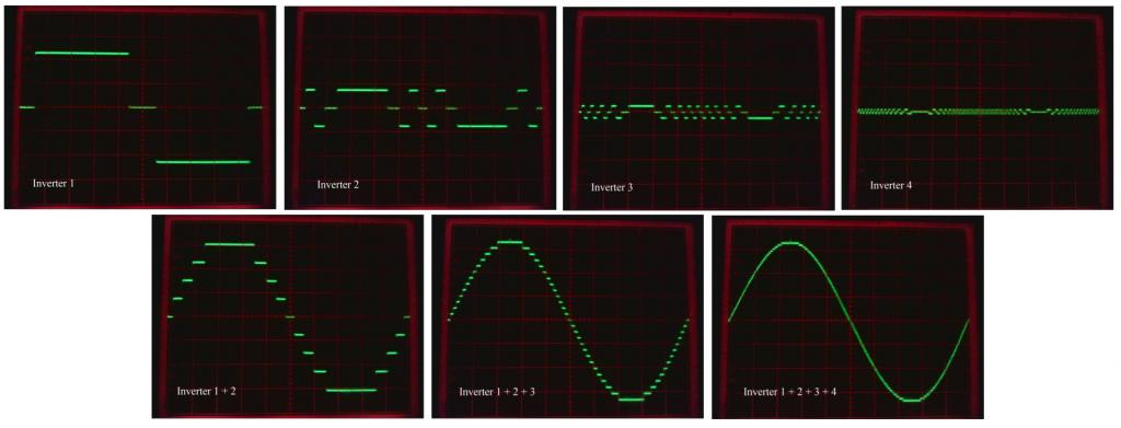 Edited 2021-01-11 19:30 by Warpspeed |
||||||
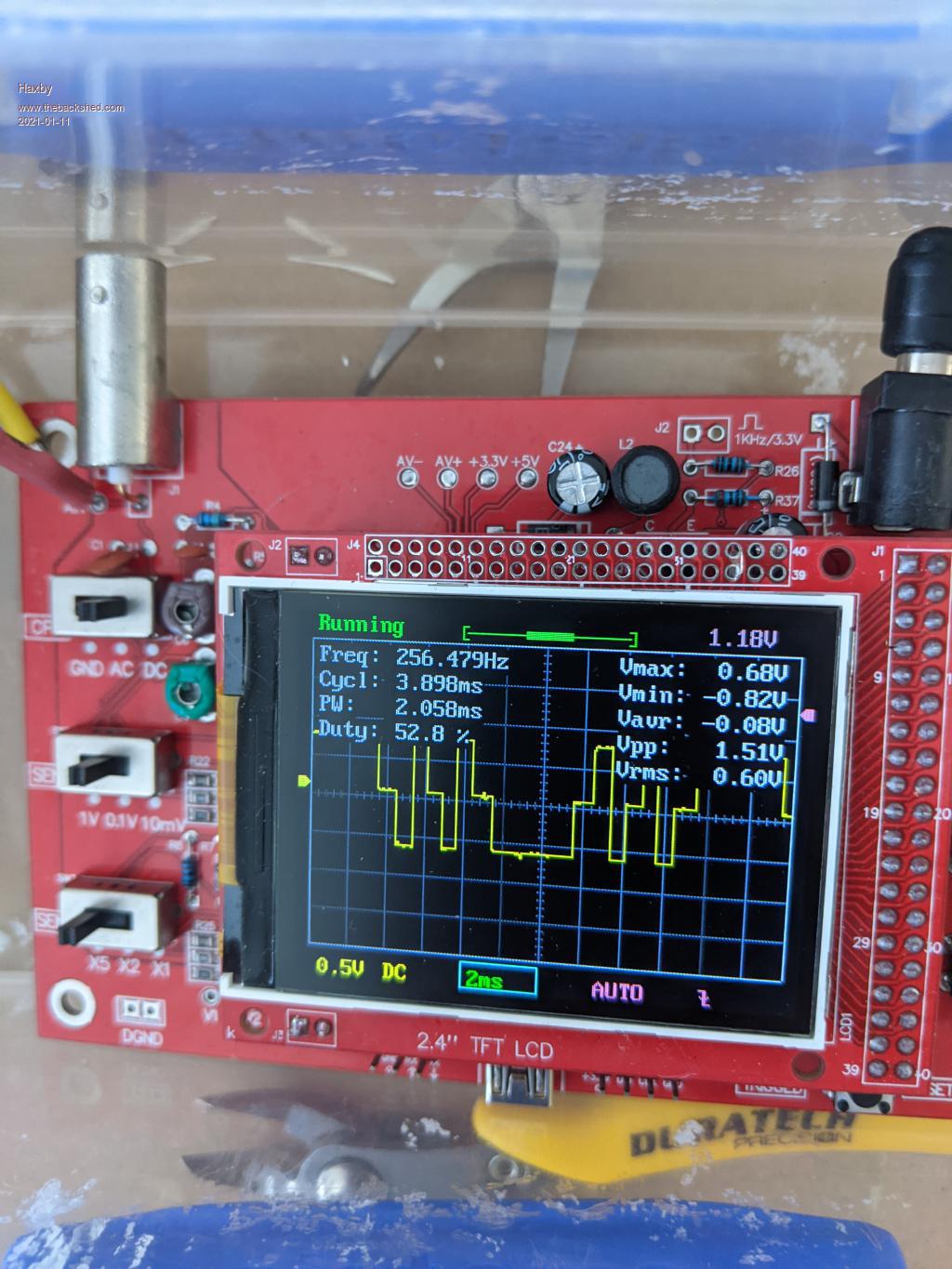
Ok this next one is on the output of the second largest inverter on its own.(transformer output side) Does this look ok? 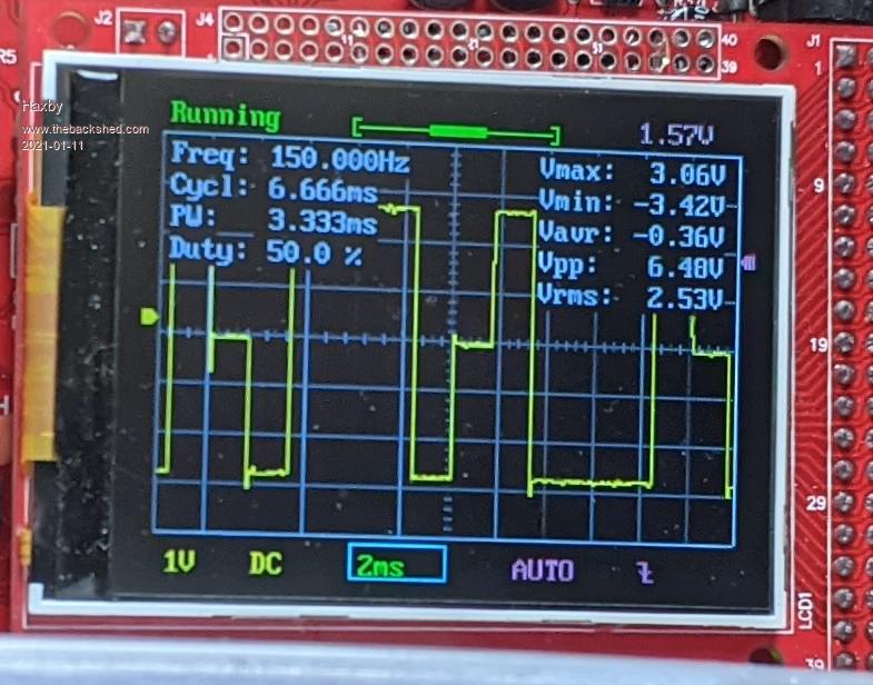 |
||||||
The transformer was buzzing before the IGBTs failed. It was buzzing more than the large inverter transformer. Maybe that's a clue. |
||||||
That last image is with the warpverter set to output the lowest voltage possible, as I applied 4v to the feedback on the ADC. |
||||||
I always test at minimum dc input voltage which produces the maximum number of small output steps. At twice the dc input voltage, the steps will all be twice as large, but only about half the number of steps, and that will greatly change all of the the drive waveforms. This is my inverter (with the smallest number four inverter disconnected). At minimum dc input voltage (90v) there are the full 27 steps. 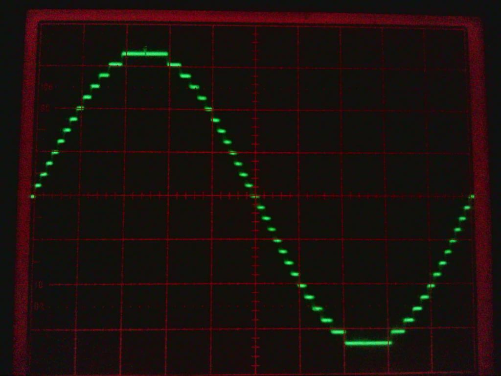 With the dc input voltage doubled to 180v, the inverter ac output amplitude stays the same, but the individual steps become twice as high, but only 15 of them. 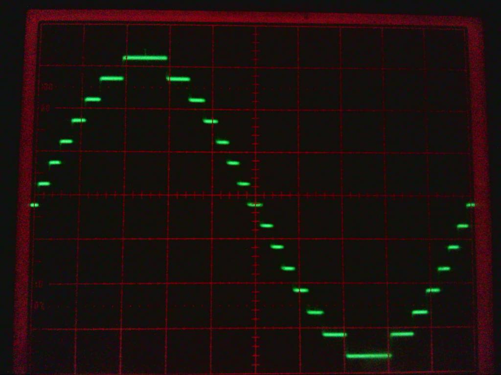 I never bothered to record the actual driver waveform shapes doing this, but obviously there are going to be very large differences between the lowest and highest lookup tables. With the smallest inverter connected up, the inverter output waveforms are far less lumpy, and its more difficult to demonstrate how the voltage regulation actually works. |
||||||
Could it be a back EMF problem? You are using 1200v IGBTs with a 100v supply while I'm using 600v IGBTs with a 330v supply. I'd have to buy some better test equipment to look into that. |
||||||
No, because your IGBTs should have an inverse diode, same as a mosfet. The peak collector voltage can never exceed the dc supply rail voltage. Just checked, yours do have the diode inverse, not all do. https://ru.mouser.com/datasheet/2/196/Infineon-IKFW90N60EH3-DS-v02_01-EN-1369182.pdf Edited 2021-01-12 08:43 by Warpspeed |
||||||
Ok I'm pretty sure that the traces are doing what they should do. It's as if the transformer is saturating at higher voltages. I'll rebuild the IGBTs and start with lower voltages and work my way up again. I have a hall effect current meter that I can clamp on one transformer leg. That might show if it's saturating. |
||||||
Put a resistive load on the inverter, maybe a light bulb or something. There should be a perfect sine wave current in all of the primaries. Primary voltages will be switched square waves, but the currents will be sinusoidal. As you say, transformer saturation will show up as high current peaks. |
||||||
Ok I was able to catch the fault on camera! here The core does seem to be saturating, but not immediately. I power on just before the video starts, and within a few seconds the core saturates! I then pull out the plug and the voltage slowly dies away. This is repeatable, every single time a few seconds after power up. I have limited the transformer current through a 5 ohm resistor, so at least there are no more blown IGBTs. The oscilloscope is measuring the voltage across the 5 ohm resistor. No load connected. This is with 140v DC square wave going into a 230v transformer winding. I also tried another large (3kva) toroid and it did the same thing. I tried a smaller (still 350va) E-I transformer and it did NOT saturate. What on earth is going on! |
||||||
The only thing I can think of right now is staircase saturation, where the core is driven slightly more (or for longer) in one direction than the other. That tends to ratchet up towards core saturation in one direction after many cycles. It means the positive and negative half cycles are not symmetrical for some reason, if that is actually the cause of what we are seeing ? Now I don't think it can be the data in the eprom, because nobody else is reporting this problem, and all the eproms are identical. Try feeding the same drive waveform from the control board into a different power stage, and see if it still does it with that same transformer. That might indicate if the unsymmetrical waveform is coming from the driver board or if its in the power stage. |
||||||
The large inverter does it first but at a higher voltage the medium inverter does it too. Not sure about the smaller ones. I'll experiment more tomorrow. I think it could be some effect that is exacerbated due to the higher voltages I'm using? Judging by the buzzing sound it makes, it definitely builds up slowly then locks on. Very intriguing. At least I'm getting closer to finding the cause. |
||||||
Commercial transformers are designed to run at a fairly high flux density to minimise the amount of copper and steel, to crate a smaller and lower cost transformer for a given power level. That makes them much more prone to saturation problems, and a lot more sensitive to any slight unbalance in the ac drive waveform. I am rather surprised that you are seeing this effect with only a 140v dc supply. |
||||||
Ok more testing this morning with a fresh brain.... This was the first time I traced the output terminals of the inverter with a transformer connected. You can see that while the high/low times look symmetrical, the "off" time is not. No idea why this is so.... 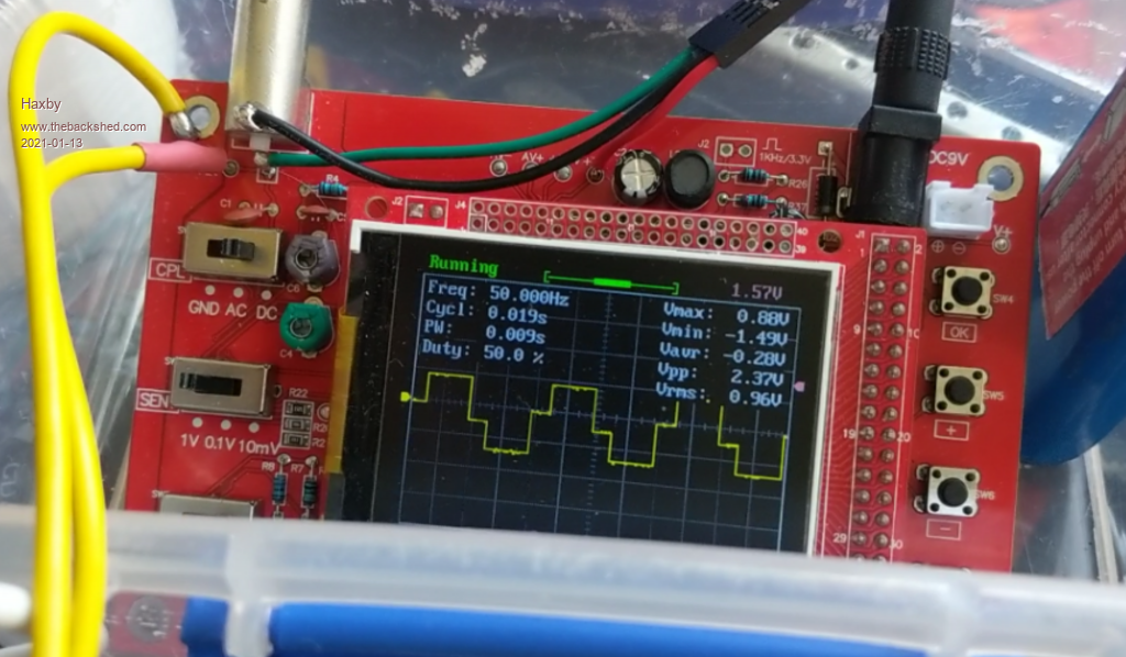 |
||||||
That waveform is not right ! Its not returning to exact zero in the middle. The positive and negative peak values are when a pair of diagonal IGBTs turn on. The zero point is when either a pair of upper, or a pair of lower IGBTs turn on simultaneously and place a dead short across the transformer primary. It does not matter which pair turn on together (both uppers or both lowers), either will work fine, but that does not seem to be happening. That is your problem for sure. Now we need to work out why ? Should look like this: 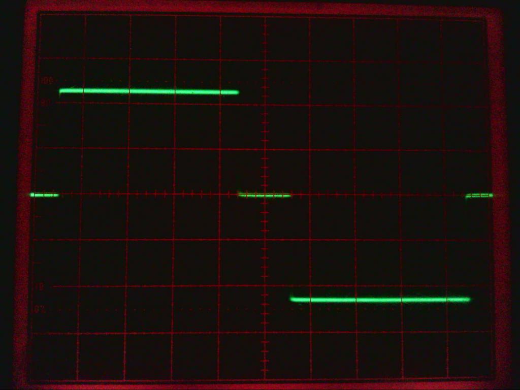 Edited 2021-01-13 09:39 by Warpspeed |
||||||
Aha, I think I've got it: I didn't think it was worth mentioning that one of the stages uses different IGBTs. Ixgn320n60 Well of course I looked up the data sheet, and they don't have an internal diode! A few 1n4007 diodes later and it seems to be working! |
||||||

