| Menu | JAQForum Ver 19.10.27 |
| Menu | JAQForum Ver 19.10.27 |
Forum Index : Electronics : Turning a Toyota Prius into a "portable" generator
Thanks Warp, Now before I install it in my Prius, and hit it with some decent loads, what are your thoughts on completely isolating the warpverter board from the 200-400vdc supply? Specifically, the battery voltage sensing 2-4v input part. I was thinking of using an analog optocoupler for the voltage reference instead of the existing resistor divider and pot. Any thoughts on that? |
||||||
Standard isolated SMPS designs use optocouplers in the linear region for feedback. I don't know diddly about Warpverters however. One cheap trick I have used to allow me to control existing motor speed controllers with a microcontroller is to replace a pot with an LDR and PWM an LED in front of it. It works freaking fantastic. But LDRs are pretty slow and so might not be suited to inverter feedback timing. |
||||||
InPhase: The warpverter is isolated by way of the onboard switch mode power supply, and all the outputs are optocoupled. The one remaining non-isolated point of the circuit is the voltage sense input, which uses a resistor divider to feed a 2v-4v signal into an ADC. 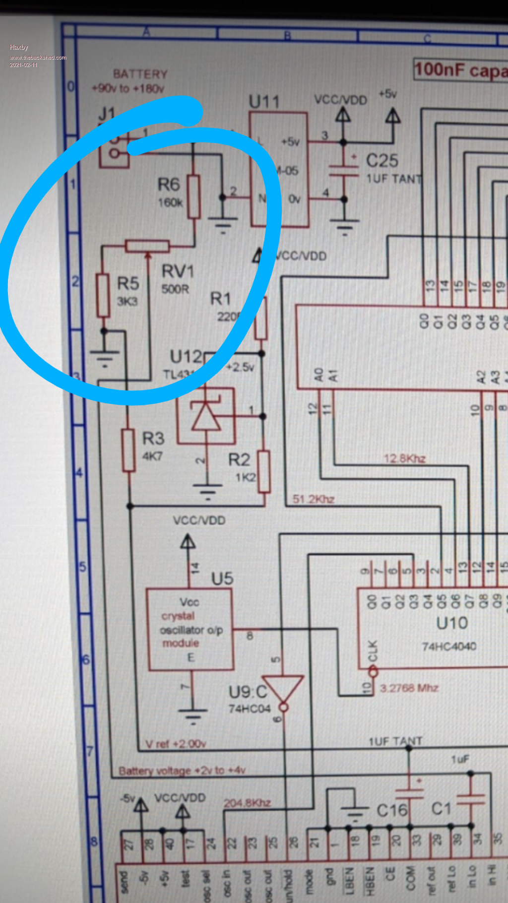 Since I am using higher voltages than it may have been designed for, I'm debating the merits of swapping the resistor divider to an analog optocoupler, rather than just increasing the resistor divider values. |
||||||
Please use a resistive voltage divider, its the key to having excellent long term voltage stability. What voltage did you wind your primaries for ? |
||||||
All 4 are essentially unmodified 230v mains transformers, except for a few back turns to get the voltages right. Large: unmodified 3kw aerosharp 230v:250v Medium: 1.5kw aerosharp 230v:93v Small: 300w 230v:30v Tiny: 150w 230v:10v So at 200v input, the output voltages are closer to the required 225,75,25,8.3 and a few external turns were added to get the voltages spot on. |
||||||
O/k, I should have remembered  Try R5 = 3K3 RV1 = 1K R6 = 430K You should be able to tweak the warpverter output voltage with RV1 between about 202v rms to 263v rms. |
||||||
Not having to wind giant transformers is a great advantage for me! That's why a 3 phase version of my inverter is a tempting thought. I already have all the parts required. I just need to convince Poida to write that Arduino mega code  |
||||||
I did a similar thing back in the late 80s for a noiseless volume control on my home-grown amp. Was fed up that all pots eventually get noisy so I used an incandescent 6V bulb onto an ORP12, the LDR replaced the pot in the volume control and the pot now controlled the incandescent bulb. It was a bit... you know... on the volume scale but it was *totally* noiseless in the amp. I was happy with it |
||||||
There are also opto isolators that use a fet as the output device. The fet works with dc or ac as a variable resistance, just like an LDR and light source, but its super fast. Resistance range might be a couple of hundred ohms to a couple of hundred megohms. https://www.alldatasheet.com/datasheet-pdf/pdf/52729/FAIRCHILD/H11F1.html Enjoy |
||||||
Gents, just working on a precharge circuit and I've coincidentally found a precharge relay and contactors from another Prius. 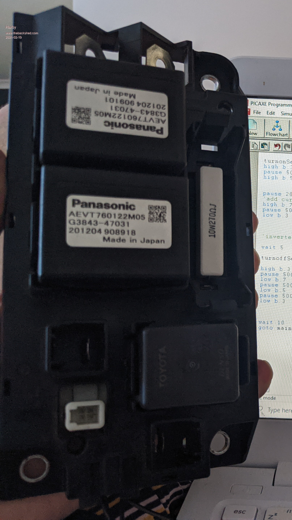 This one came from a Prius-C, which is the smaller variant and only has a 150vdc battery. I plan on running my inverter at up to 400v. The relays are rated for 400v, so all good there. But the stock precharge resistor is 30 ohms which at up to 400v input is 13 amps. The design load in the PriusC would have been around 5A and a very short pre-charge time. Size wise, the stock precharge resistor looks to be about 30w if I was to guess, but by my calculations it would have to withstand 750w momentarily. So I want to change the resistor value to something more gentle. What about 2x270 ohm 10w resistors in series? I've got them on hand. So 540 ohm So at 400v, initial current = 1.35A Initial power 540w Time constant = 2.7 seconds Am I pushing it? I don't have a data sheet for these resistors. They are just from Jaycar. |
||||||
Should work, and probably for a very long time. If the resistors do fail open circuit (due to thermal shock) just fit bigger ones. |
||||||
Is there a practical way I can measure EMI with my oscilloscope? I have built a circuit to control the power up sequence of the inverter. It consists of a processor that has two momentary switches, one for on, one for off, as well as control for 4 relays, being the pre-charge resistor relay, the high side DC contactor, low side DC contactor, and 240v output relay. The processor sequences the relays/contactors as required to turn the system on or off...... In practice, the circuit works fine when I'm powering the inverter from 200v, but at 250vdc or more there seems to be enough EMI picked up by the processor that it thinks pushbuttons are being pressed when they are not! The processor is not resetting, so it's not a 5v power stability issue. The phantom button presses are being picked up by a 10cm long wire that goes from the processor to the front panel switch. The pulldown resistor is 10k. I can decrease the pulldown resistor to a lower value and add capacitor, which will eliminate the problem, but I think that might mask a high EMI issue emanating from the IGBTs. Is there a practical way I can measure EMI with my DSO? I guess that the fast HV peak-to-peak transitions are causing EMI. I have tried to slow down the rise/fall time of the IGBTs by adding gate capacitance, but maybe I should add an inductor to each transformer as well? |
||||||
I don't know about measuring EMI with an oscilloscope, but an old AM radio will do. |
||||||
I made a wand by shorting out the oscilloscope probe. See pic bottom left. 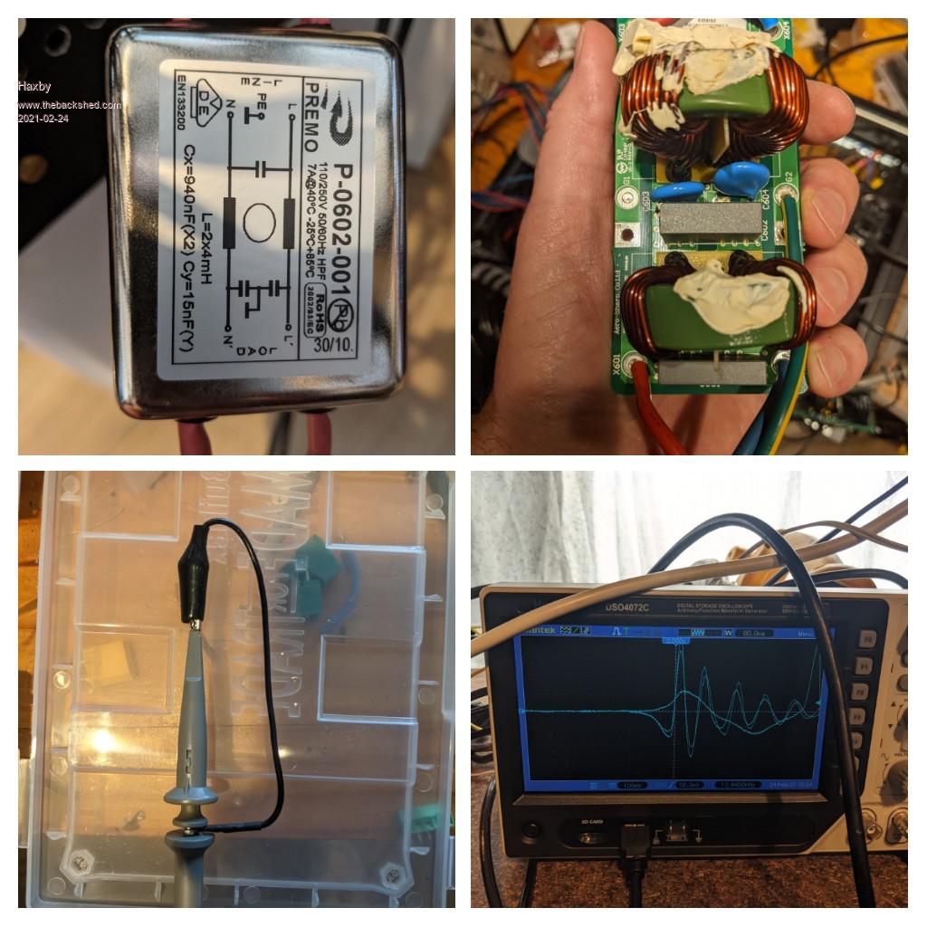 With the wand, I measured up to 1v p-p of noise in the DC input wires. The noise was everywhere along the DC line, not just current carrying wires. So I installed a filter in the 240v output, see top left pic, and another filter (top right pic) in the DC input section. Now the noise stops at the input and output filters, but internally the noise is still very much there. It's also in the wires between the igbt PCB and the transformers. Should I: A. Not worry about it B. Add 4 X filters to each inverter output between inverter IGBTs and transformer. C. Something else? |
||||||
Would a ferrite bead around the switch conductors help? I've seen them do all sorts of magic in other signal wires. Cheap and easy too. |
||||||
It couldn't hurt. I replaced the 10k pulldown resistor with a pretty heavy 330 ohm one. Works fine now, but I'm not sure if I should be concerned about the radiated EMI. An AM radio does pick it up, but it also picks up my fully approved new 10kw solar system too, so I don't know the magnitude of the issue. I'll definitely add a filter for the DC rail that powers the little hi-link switch mode power supplies. |
||||||
As long as currents are switching on and off rapidly, there will be some radiated emission. A grounded metal enclosure might be the answer. |
||||||
Haxby: I've made a 3 phase warpverter driver. It needs the Arduino Mega. The code is for a 4 transformer warpverter so it has 8 digital control outputs for each of the 3 phases. I use the mega's PORTA, PORTC and PORTK pins. This is 24 pins that will drive either the low or high side of a half bridge. 24 half bridges or 12 full bridge inverters..... There are two versions of the code. One takes a voltage feedback from one phase only, and this is used to maintain voltage output via my usual closed loop control. Vfb is about 2.5V for nominal output and it is pin A0 The other takes Vfb from A0, A1 and A2 and then individually controls the output voltage for each phase. This permits some degree of unbalanced load on the 3 phases. PORTK = A0, PORTA = A1, PORTC = A2 (if you get this mixed up the output voltage will not have a nice feedback control loop) As usual, you need to drive D8 to logic HIGH to run the inverter. Pull it down to ground (logic LOW) to stop it. There is a soft start and soft stop. No SCR over current immediate stop function enabled but just change one line near the bottom of the code, it should be clear to see. Ensure Vfb is noise free. I suggest an RC filter on the signal as close as possible to A0, A1, A2 similar to what I have done with the brainboard for the MPPT. mega_no_sync_3ph.zip mega_no_sync_3ph_3vfb.zip Purple is D9, a sync pulse for the DSO The others are decoded warpverter drive signals that are then converted to analog voltages. 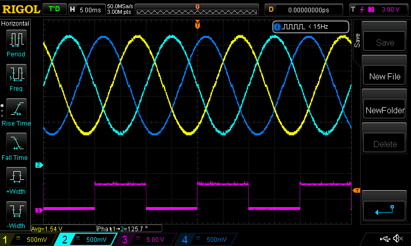 have fun. make sure to video first time power ups so we can enjoy the fireworks!! |
||||||
Thanks for your work Poida, I'll try it with 3 of my igbt power boards. I'll design a shield PCB with some 74hc04's as per the warpverter board. Breadboarding it would be a big rats nest! Another big thankyou. This will be another great advancement in the warpverter chronicles! |
||||||
How did you get the traces on the scope? Do you have 3 warpverters? |
||||||

