
|
|
Forum Index : Windmills : visual effect of capacitors
| Author | Message | ||||
SparWeb Senior Member Joined: 17/04/2008 Location: CanadaPosts: 196 |
...From the formula for resonance F = 1 over 2 Pi sqrt LC or it's derivative LC = 1 over 4 times Pi sq times F sq we can theoretically calculate caps for all series F&P. Then why don't I see anybody working out an example to show it? Xc = 1/(2*pi*f*C) and Xi = 2*pi*f*L and fc = 1/2*pi*sqrt(LC) Somebody has all the numbers ready to fill it in... I'd do it myself, but I'm sure somebody will come along and say it's not that easy. Get that guy to work it out, then. The math is simple to write and follow, and then we wouldn't be speculating about whether Gordon's mill runs above, at, or below the resonant frequency. I'm going out on a limb and I'll say then that Gordon's mill seems to have just reached the resonant frequency with his series of capacitors when it's at 430 RPM and gets his 18 Amps. I'm using numbers posted back and forth on this thread so I can't tell if they apply to the same condition. Somebody out there who didn't just learn AC circuit analysis yesterday (like I did) can correct me if I'm wrong. Steven T. Fahey |
||||
herbnz Senior Member Joined: 18/02/2007 Location: New ZealandPosts: 258 |
Hi All As stated away back I have a test rig and are working on Capacitors on FP. I will not comment on results yet. I will however raise a couple of issues re generator theory. There is no self inductance in the stator coils while generating, reason the current in the coil can not produce flux it is overridern by the rotor flux if not we would not generate. In other words the mmf from the rotor must be greater than the mmf from the stator coils. So simple Xc = Xl is not valid. What does happen in all generators is as stator mmf increases with load the rotor lags back in time, try using a stroboscope triggered to flash sycronised to the rotation. This effectivly reduces the flux to the coils. capacitors advance this lag. I will not say more at the moment as disscussions on therory have not been accepted on here. Herb |
||||
| Dinges Senior Member Joined: 04/01/2008 Location: AlbaniaPosts: 510 |
Reading this thread I'm reminded of Zubbly's experiments with a 7.5 hp motorconversion in a heating application, using capacitors: http://www.fieldlines.com/story/2006/10/29/201016/09 I vaguely recalled having done some calculations for him back then... fortunately, I posted about it (#47), or I would have forgotten all details about it... 
I'm not sure the resonant theory is correct. If it is, there's still another practical problem, determining/measuring inductance of the generator. From Flux's explanations (long time ago, can't refind the thread) I recall that it's not as simple as hooking up an inductance meter and reading the value. Apparently the rotor comes into play too, and the 'real' inductance is also dependent on the speed of the rotor, IIRC. I don't know how one could easily measure or determine the correct inductance. If anyone knows how to, please explain. As stated, I'm not sure the resonant theory is correct. Recalling Oztules' recent experiments, where he used an axial flux in a heating experiment, I think it's interesting to have a look at the load characteristics of battery charging (standard), battery charging with capacitors in series, and heating: In Oz's heating experiment, voltage goes up as RPM and windspeed go up; the voltage isn't clamped by the battery: as RPM rises, voltage rises; the curve is a rising line. Recall that Oz mentions a relatively large power, larger than when battery charging. Obviously the load, generator and wind are better matched somehow. In a plain battery charging application however, voltage is clamped by the battery. As RPM goes up, voltage stays the same. The curve is basically a horizontal line. In a battery charging application with series capacitors, we see the effect that at low RPMs the caps present a relatively large impedance, thus reducing available voltage (and current) for charging. As RPMs rise the impedance decreases. The new (combined) voltage curve of the batteryload and capacitors is again rising, due to the lowering of the capacitors' impedance as RPM rises. At higher RPMs the capacitors basically disappear and the flat, horizontal curve of the battery is dominant. Keeping Oztules' recent experiments with water heating in mind, the similarity of the curves in both situations (heating and batterycharging with caps) may explain the higher observed powers. At least, that is my guess. As in Zubbly's experiments, the extra impedance of the capacitors disappears as RPM (and thus AC frequency) increases. It's my suspicion that it is this that causes a better matching of the (battery)load to the windturbine and/or wind. (devious thought: I wonder; does wind have an impedance, as for example space does to RF?) The above may or may not be the same thing as matching with caps to achieve resonance; one would have to fill in the figures and do some math; it may very well be that both explanations explain the very same observed phenomenon in two different ways. Or does anyone know how to determine whether it's a matching issue or a case of powerfactor correction (PFC) of the inductive component ? If it's a matching improvement, replacing the caps by resistors (of the correct value at the specific RPM/frequency/windspeed) should have the same effect on power output. If it's a powerfactor correction thing (to correct for inductive impedances), series resistors would not yield the same results as series capacitors. |
||||
oztules Guru Joined: 26/07/2007 Location: AustraliaPosts: 1686 |
Dinges, the blades already overpowered the mill, so resistance won't help. Inductive reactance killed it off at 11 or 12 amps... so this is the culprit. I have a lot of time for Gills explanation, and it fits the facts pretty darn well. It is the only decent reason I can see for getting the amps up. I entertained some wild ideas about how the caps could increase the current some other way, but they didn't hold up. In the end it was the effective lowering of the resistance (by lowering the ac impedance ) of the coils that was the key.... then the dc wire resistance ceased to be the limiting factor. I think the other thing with the MPPT argument, is that you can never recover the cubic function of the wind with any gadgetry..... because the alternator only goes up with the square of the blade speed. The blades only go up linearly with the air speed, but the wind is doing it's own thing as a cube of the wind speed.... so I think squared is as good as it gets. If you can hold the R losses by resonance at the point where your max power is, I think it will be as good as it gets. If you look at Gills graph, it is a X sq looking curve with frequency.... which is exactly what we want to match the alternators X sq output. If the caps are chosen well, I suspect no amount of gagetry will beat this arrangement for MPPT..... the alternator is just not capable of X cube performance. (W=Esq/R)...... Now this extra magnitude that we can't track with the alternator, may show up partially. If we assume that the blades will speed up a little as they are not being loaded correctly as the practical wind rises, we may get a bit more voltage than we would have... ie the rpm increases over linear as we increase wind speed, but by how much, and do we use that advantage already... I'm sure we do as the alternator will take up the extra rpm .....until the blades finally win the tussle and finally overpowers the alternator. This may skew the calculated cap value for wind speed..... but not rpm. All in all I think we are slowly getting to the bottom of this. .........oztules Village idiot...or... just another hack out of his depth |
||||
| Dinges Senior Member Joined: 04/01/2008 Location: AlbaniaPosts: 510 |
Ah ok, missed that. Yes, that seems to basically rule out the capacitors acting as 'powerless resistors' to match the genny to the load. Now with the series-LC circuit analogy all kind of other thoughts prop up... Like Q-factor. What would the Q of a F&P be ? If it's high, would it be beneficial to lower it (with a series damping resistor) so the resonance peak becomes broader and thus bandwidth increases? Or maybe 'stagger tuning', as used in IF filters ? Have one phase tuned to a certain frequency, phase two to a slightly different one, and phase 3 to yet another frequency. This would broaden the curve (but also lead to imbalance between the phases). Or even continuous tuning, by switching in or out capacitors (via relays? SSR?) to make sure that there's always the right amount of capacitance to achieve resonance at any frequency (RPM) ? Plenty of (silly) ideas come to mind... If anyone knows how to determine the inductance of a generator, I'd be very interested. I once measured the inductance of the 10 hp conversion stock winding with the LC meter (11.7 mH per phase), but was later corrected by Flux that this wasn't the 'true' inductance, as it didn't take into account the effect of the (rotating) rotor. For the series-LC technique to work one would need to have an idea of the generator inductance with which to calculate required C at a desired F (=RPM), so the inductance measurement issue becomes real. Or one would have to resort to trial and error. |
||||
Gill Senior Member Joined: 11/11/2006 Location: AustraliaPosts: 669 |
Certainly, I'll concede there may well be influences that cause a variance to the resonance equation in theory and practical terms, though it is the basis of my rational. Observation and experimentation will reveal this if our knowledge of theory cannot. oztuls, I disagree with this though here is not the place for that debate. I do agree here at least for the stage 1 of my MPPT proposal and provided blades are correctly chosen, though I don't see it negating the need for stage 2. Again that's not the main thrust of this topic either so I must let that go for another time too. I have tried to get measured values for the inductance in the stator but both my analysers suit frequencies from 500kHz, 1.8mHz and above. I never do well at measuring impedances.  was working fine... til the smoke got out. Cheers Gill _Cairns, FNQ |
||||
| GWatPE Senior Member Joined: 01/09/2006 Location: AustraliaPosts: 2127 |
I have checked the AC voltage across the capacitors with the mill operating. voltage measured across the capacitor appears to be sort of proportional to mill rpm. I have no way of correlating this yet. I may have to build a variable speed test bench myself. Trying to measure and record the many parameters on a mill in the wind is becoming difficult now. Too many of the measurements require electrical isolation. I will need to score a 2hp AC motor and drive a F&P directly. I have a VFD on loan, so I can possibly set up a suitable test rig myself. The capacitors seem to behave in a similar way to a series resistor. The benefit is the power is transferred to the load instead of being dissipated in the resistor. the power gained is similar to what would be dissipated in the windings and a resistor. On a previous occasion I measured 550W with caps, this was an increase from a maximum of about 280W without caps. Today I measured 25VAC across the caps for about 10A battery current. An equivalent series resistor of 2.5ohm for the 3phases would give similar voltage drops at the measured currents. This would equate to a power dissipated of around 250W. The caps do not behave this way though. This is how I see what is happening; The charging and discharging of the caps within the cycle is the mechanism for transferring the additional current to the load. The diodes do not allow current out of the battery and so the capacitors charge up, by drawing current from the coil. As soon as the voltage reverses, the stored energy is pushed though the diodes and the capacitor starts to charge in the opposite direction. The total current is the sum of the coil current plus the additional current from the capacitor. Additional bypass capacitors on both sides of the main cap will possibly reduce some of the diode switching spikes. A normal charge pump works with a capacitor at a frequency above the series resonant frequency of the cap. Normally a square wave is used. The steering diodes provide a doubling function. These can be stacked to give multiples of the original peak to peak waveform. The cap is an effective isolated short cct. In the windmill scenario, the cap has to be charged and discharged. If the cap becomes an effective short cct, then there is no benefit to power output. My testing puts the operating range of the mill to be well below the series resonant frequency. The inductance of the coil is the primary constraint. We would all benefit from knowing the inductance. I do not have an inductance meter either. I have estimated a 100S in delta has an inductance of 2mH. The inductance has to be at least lower than 2mH for capacitors to be effective. The combination of the coil resistance and the inductance and the cap ESR and the wiring resistance determins the resonant frequency. In my simulation I used a coil resistance of 1ohm and an inductance of 2mH and a wiring/capESR resistance of 0.1ohms. The cap is 230uF. The series resonant frequency is 246Hz for other cap values 50uF 490Hz 100uF 350Hz 150uF 290Hz 200uF 250Hz 250uF 225Hz 500uF 160Hz If the inductance is doubled the series resonant frequencies for varying caps are 50uF 350Hz 100uF 245Hz 150uF 207Hz 200uF 175Hz 250uF 160Hz 500uF 104Hz The F&P stator has a frequency of 28Hz at 60 rpm. So for 400rpm this gives a frequency of 187Hz I chose 500rpm as the upper rpm, 233Hz. this gave a cap of 230uF for 2mH at the series resonant frequency. If the inductance is doubled, then the 233Hz upper limit requires aabout 120uF. I considered this too small a cap to transfer much useful power. energy stored in a cap = 1/2 x C x emf^2 so size is important. If the inductance is halved then the cap size can increase. Smaller inductance is better. The cap size is chosen for the power levels, too much reduces effectiveness. 500W appears to be 250uF. 1000W would require 470uF and the same inductance, for the same pole count and rpm. This is about as far as I will speculate until I am able to quantify with measurements or the various stator wiring combination inductances are known. 24V F&P systems appear to be able to benefit most from caps. The inductance should be proportional to the number of turns. There is published info on this. I am sure Dr Chalko calculated a stator inductance. Gordon. become more energy aware |
||||
| SparWeb Senior Member Joined: 17/04/2008 Location: CanadaPosts: 196 |
[quote]If anyone knows how to determine the inductance of a generator, I'd be very interested. [/quote] You might want to check out this stuff: http://www.eng-tips.com/viewthread.cfm?qid=226803&page=1 ...check out every link on that forum thread, and especially don't miss this from "electricpete": http://home.comcast.net/~electricpete1/torque_web/ After downloading all that stuff, it really puts the write-ups you and I do to shame, doesn't it!? 
I admit it's pretty heavy going. It's getting to be over my head, too. But it is filling in lots of blanks for me. The interest for him, of course, is in induction motors, not in generators, and the geometry must be reversed for a F&P. Setting these differences aside, I think there is a lot to be learned. It doesn't answer the question at hand, I admit, but it does open a window on the mutual induction between rotor and stator. With some research I think the answer to your questions can be found. Steven T. Fahey |
||||
Bryan1 Guru Joined: 22/02/2006 Location: AustraliaPosts: 1209 |
Hiya Guy's, Gordon your reference about the 2hp motor and VFD I suppose are headed in my direction and yea mate if we really want to down and dirty into this I can make up a test rig using the above and have Gordon here as the supervisor. Now I did see a q meter in the silly chip mag a few years ago buy it used a bloody avr not a pic  . If we go ahead with this test bench it will need to have all the guages so for a jobbie like this a picaxe won't cut the mustard so I'd better think about making that LC meter sillychip did a few months back but with a twist as I hate just copying projects. The test bench will need to cater for different gennies so that will take some thought, so time for a big think tank to get this baby going. . If we go ahead with this test bench it will need to have all the guages so for a jobbie like this a picaxe won't cut the mustard so I'd better think about making that LC meter sillychip did a few months back but with a twist as I hate just copying projects. The test bench will need to cater for different gennies so that will take some thought, so time for a big think tank to get this baby going.
Cheers Bryan  |
||||
| GWatPE Senior Member Joined: 01/09/2006 Location: AustraliaPosts: 2127 |
Hi sparweb, I have no intention of going back to school. There may be some percentage of readers who could wade through the physics. I did the engineering and scientific theory a long time ago. I am finding logical testing of ideas and trial and error are helping me more than a calculated system. I still use a spreadsheet and graphs to visualize trends, but I have no desire to prove theories on paper anymore. A UNI student hoping to do a PhD may take up this in a scientific way. Dr Chalko did not measure the stator inductance, but mentioned that the inductance was complicated with rotation speed. Hi Bryan, I have to take a break for a while from windmills. My F&P is working really well now. I hope other readers with 24V and 12V systems do try the series arrangement of capacitors and provide some feedback. I have no desire to write a paper on my findings. I am not going to test all the inter relationships that are possible. Hi oztules, I think that your axial flux mill will benefit significantly with series caps. The caps will probably need to be a ,000's of uF for the power your mill can produce. I would even think that your mill could be connected to 24V or 48V battery. The caps could allow 3-5kW into the 48V battery. Imagine 100A. Better make the grid your friend. I think the caps and inductance relationship is a non linear one. There may well be a close to ideal loading. The bottom end before cutin is still benefited with a boost cct. I think that furling ruins the cubic relationship more at the top end, so no point in pushing things too far. I will be monitoring the caps over time. Some one with an anemometer and other logging would be an ideal candidate to trial and provide some additional feedback. BTW I determined that the important stator inductance value was close to 2mH as with 230uF cap this is the combination that is parallel resonant at about 200Hz. This is where I saw the mill output fall to zero. This is why I chose the same value for the series caps. Gordon. PS I had looked at if a smaller cap would be better, but there is a tradeoff with the slightly higher resonant frequency with the reduced energy transfer function provided by the cap. The cap has to be the right size so that the voltage developed across it only effectively allows the mill voltage to double and not much more. I have seen a doubling of mill output. A buck converter seems to be a waste of time if caps can allow the transmission of current at a higher voltage. High currents at battery voltage at the high power levels seem to be avoided. Wiring loss at high power levels may be reduced to half. become more energy aware |
||||
| oztules Guru Joined: 26/07/2007 Location: AustraliaPosts: 1686 |
Dinges....you said: "Plenty of (silly) ideas come to mind... If anyone knows how to determine the inductance of a generator, I'd be very interested. I once measured the inductance of the 10 hp conversion stock winding with the LC meter (11.7 mH per phase), but was later corrected by Flux that this wasn't the 'true' inductance, as it didn't take into account the effect of the (rotating) rotor. For the series-LC technique to work one would need to have an idea of the generator inductance with which to calculate required C at a desired F (=RPM), so the inductance measurement issue becomes real. Or one would have to resort to trial and error." Do you recall from your discussion with Flux, just what was the broad relationship with rpm and inductance? The reason I ask, is coupled with Gordons wrap up of events, it occurs to me that the reason he is seeing a reasonable positive result throughout a fair part of the range, is that the inductance is changing with frequency, and that this may be giving a fairly broad spectrum where the resonance is useful, rather than a high Q circuit where it works for a narrow frequency band only...? It may be happy coincidence that the TSR can pick up if we are way off Q, and the frequency shift may catch back up closer to resonance and reload the prop better.... that didn't come out quite right, but I can't think of a way to express what may be a dynamic relationship between the prop and the possibly variable tuned circuit. Put another way, does the inductance of the stator go up with rpm or down..... Gordon.... 100A@48v..... be afraid.... be very afraid. 
It is already capable of 5kw and over with small loss in the stator with 4R load, It does over 2kw straight into the batteries, but at probably 50% efficiency. I think I can scrounge up a dozen or more 5000uf 60v caps, but that won't be enough for series paralleling them to clear the voltage hurdle, so I will see what else I can get hold of. Well done again, and you have ended up with a happy mill to boot. .........oztules Village idiot...or... just another hack out of his depth |
||||
| GWatPE Senior Member Joined: 01/09/2006 Location: AustraliaPosts: 2127 |
Hi oztules, You might need 10000uF @ 200VAC, the lower frequency output would mean more capacitance. I see the 5kW would be very possible into the battery. Maybe a bigger battery. I think you mentioned 6pole pairs of magnets, so 300rpm gives 25Hz. 20000uF would be a good start per phase. The lower frequency means 8 times the capacitance and then the 10fold power level would mean 10 times the capacitance again. 230 x 8 x 10 = 18000uF. This is a serious capacitor for a serious amount of power. Maybe not a way to go. Need to up the pole count for realistic use of capacitance on your mill. Gordon. become more energy aware |
||||
| oztules Guru Joined: 26/07/2007 Location: AustraliaPosts: 1686 |
Gordon, I was kinda hoping 300rpm was closer to 30 hz.... see smaller caps already 
........oztules Village idiot...or... just another hack out of his depth |
||||
| SparWeb Senior Member Joined: 17/04/2008 Location: CanadaPosts: 196 |
18000 uF.... assuming the inductance with which you want to resonate is the same as the F&P's. It isn't likely in an axial flux machine. A motor conversion would be different again, and for different reasons, too. Trial and error it is, then! Steven T. Fahey |
||||
| GWatPE Senior Member Joined: 01/09/2006 Location: AustraliaPosts: 2127 |
Hi oztules, it was late, yes 30Hz. I covered both bases as I had said 10000uF would be a start. I see much activity on fieldlines. I will add caps to my axial flux mill. I have noticed that the axial, being electrically stiff should benefit as well, as the caps will add a degree of sponginess. The rotor will be allowed to spin up a bit faster during peak power in a wind gust. At the moment the battery holds the rpm down and the blade tsr drops. Better to get the voltage to current conversion to happen outside the stator, as the stator only heats up with current. This cap phenomena will probably simplify design of all AC generators in windmill applications. Gordon. become more energy aware |
||||
| oztules Guru Joined: 26/07/2007 Location: AustraliaPosts: 1686 |
Yes Bryan started a useful discussion over there, and I felt the need to chime in as it looked like it would die after Flux's first response..... so I stole your work and fired the discussion back up.
The difference in sentiment from Flux's first response to his last means that it was explored sufficiently well for even him to come around..... I take this to mean it must have some serious merit. For Glen it must be pleasing that Flux see's a glimmer of hope for the F@P: Flux: "With them in series you have found a way to overcome the serious limitation of that type of alternator. The resonance will drastically increase the output. I initially thought that off resonance it would be no use but wind requires low levels of load in low winds and the fact that it is off resonance gives you a better match to the prop in those light winds. In its natural state The F & P is pretty hopeless, you have maximum loading when you least need it and when you really need the load then it goes reactance limited and sheds load ( reverse of what is needed for wind)." Which I think is his way of saying that it is a respectable little performer now. I believe we (mostly you) have collectively bought Dennis's idea in from out in the cold, and he is now in a better position to say "Mission Accomplished" 
Your going to need some serious capacitance yourself for that axial..... very little inductance there I suspect. But if you can do it, then the world changes just that little bit.... (perhaps we should invest in capacitor shares? )
..........oztules Village idiot...or... just another hack out of his depth |
||||
| GWatPE Senior Member Joined: 01/09/2006 Location: AustraliaPosts: 2127 |
I have just gone through some of the relationships that an ideal windmill has to have. I have taken 3 points only in the wind energy spectrum An initial say 10W at the shaft, 80W, and 640W. This corresponds to a doubling and doubling of an initial windspeed giving a starting wind energy of 30W for the particular rotor. Ideally the TSR should be constant with increasing windspeed. assume the 10W gives 100rpm and we have a nom 24V battery. [A battery presents a very low impedance] this is a sort of table for the power relationships at the various wind energies. I have tabled approx wind energy to mill rpm and mill voltage and calculated current and then battery current. 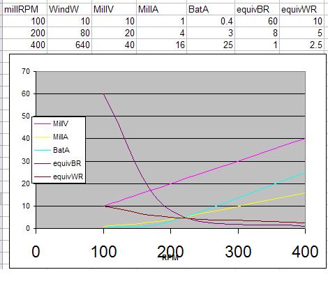
WindW = wind power at shaft millrpm millV = loaded mill voltage millA = loaded mill amps BatA = battery amperage equivBR = equivalent resistance at battery voltage to dissipate power equivWR = equivalent resistance at windmill voltage to dissipate power. The battery and windmill are not anywhere near the impedance that is required. A series capacitor creates this type of matching, as at low frequency/rpm it is a high resistance and as the frequency increases the impedance drops. I do suspect that the series caps cannot boost the voltage, so a separate boost method is required, but above the battery voltage the caps perform the required function. I need to follow up with some more testing of currents. Gordon. PS the capacitor should not be a value calculated at series resonance. become more energy aware |
||||
| GWatPE Senior Member Joined: 01/09/2006 Location: AustraliaPosts: 2127 |
I fixed the table above and provided a graph of what needs to be done by any impedance matching system. My maximiser performs this task electronically. The series caps seem to do a good job without the complexity. I have tested a rewired 80 series. I had no success with it. I suspect the cut in was too high. I did not have enough wind for thorough testing. The 100S is back up again for the moment. I have offers of motors for a test rig on all fronts. This may be my next project. So much for a rest. Gordon. become more energy aware |
||||
| oztules Guru Joined: 26/07/2007 Location: AustraliaPosts: 1686 |
hmmm... I wonder if the days of rewiring are over?? My understanding of F@P output figures is thin to say the least, but I don't recall the converted ones performing as well as the standard 100 series you have been working on. (500W) What is the phase resistance (DC) of the 100 stator you have been playing with. The rewired 80 series may benefit from parallel caps.... and then series the output through caps... I can't begin to think of what happens electrically then.... may get some interesting nodal points. Then when that fails.... maybe return the 80 to standard and test that. Holiday.... what holiday
............oztules Village idiot...or... just another hack out of his depth |
||||
| GWatPE Senior Member Joined: 01/09/2006 Location: AustraliaPosts: 2127 |
hi oztules, I have simulated a parallel and series followed by a parallel arrangement. The relationships become very peaky and I think would be difficult to reproduce in the real world. If the caps do work as a DC-DC converter and Maximiser then most problems encountered with load matching and power transmission will be solved. Transmission of power problems are current related. If the wiring is moderately sized for the average current expected and the voltage rises with the increasing power level and the caps are at the battery end, then the wiring only sees the relatively low currents and the high currents appear between the caps and the load only. I still have to measure the RMS current in the AC from the mill at high power levels. If the mill current is indeed lower, then this will confirm the DC-DC conversion of the caps. The experimental data to date does confirm this. I did measure 60VAC in the mill output and 550W. This gives i=P/V = 550/60 = 9.2A This is spread over 3 phases. The current into the battery was 550W at 28V or 19.5A The windings will only see the 9.2A instead of 19.5A. The winding loss would be reduced by a factor of 4 and so would be the transmission wiring loss. In an axial flux machine there is really only copper loss. Surely a reduction by 4 of the copper loss in the stator would still be an improvement. I do not believe that the iron is the only contributor to the performance gains. I have a second set of caps that I could test on my axial flux mill. I would have to place the caps in the yaw box with the rectifiers, as I have only 3 slip rings. I would need 8 slip rings to place caps off the mill. This is not doable. I think there will be problems with my maximiser on this mill as well. Someone else may have to follow up this aspect with an axial flux mill. BTW I passed 1A through the 3 coils in series and measured the voltage. 3.4V for 3 coils at 1A, so around 1.1 ohms DC resistance per coil. This mill is in delta, so total connected resistance is lower. Is it 0.37ohms. This would give winding resistance loss at 31W. diode loss would be 1.5x19.5=29W, The cap loss would be <10W as there was negligible heating of the caps. The iron loss is probably the same as the copper loss, 30W, so around 100W still makes heat to produce the 550W of useful power. At the 250W before caps power level, there would be the same winding loss and half the diode loss. In both cases the shaft power would be the same, so say 650W. Without caps the efficiency equates to around 38%. with caps, the efficiency equates to 84%. I suspect there are other factors in play as well without caps. Whatever is happening is a good thing. I do not see the top end power being a problem unless the furling design is poor. So what if the mill output falls a bit at the very top end due to the caps becoming an AC short. The furling should already be reducing output by then anyway. I cannot see a mill runaway as the winding current still has a way to go to the 11.5A I saw when directly connected to the battery. The arrangement I have has the stator still within 80% of maximum current before iron limiting becomes a problem. I doubt that it is worth trying to push this combo any further. Gordon. become more energy aware |
||||
