
|
|
Forum Index : Windmills : visual effect of capacitors
| Author | Message | ||||
| Dinges Senior Member Joined: 04/01/2008 Location: AlbaniaPosts: 510 |
Sorry Oztules, I googled it again some more but I can't refind it. Before I posted I searched too because I wanted to know what Flux had to say about it. It's there somewhere though. However, I'm not 100% sure it applies to our synchronous PM gennies too, or just to (asynchronous) induction motors. Steven, thanks for your links. I'll study them as soon as I can spare some time again. They look interesting. |
||||
Gill Senior Member Joined: 11/11/2006 Location: AustraliaPosts: 669 |
In the turmoil of coming to grips with the theory behind cap use, my suggestion to change the cap arrangement seems to have gone unnoticed. Flux has commented on the expected short life of caps used in the back-to-back manner and I feel this supports my suggestion. How about a pic as clarification. 
I expect the values currently used would need adjusting but when done would provide a more stable and better basis of theory calculations not to mention a longer real time life. It is my view it would dispel or confirm thoughts the interaction of the caps in this B2B arrangement is responsible for the effects noted rather than a changing power factor correction and reduced impedance as tied to Fq and at the same time matching load of generator to available wind power. If it confirmed, it would indicate to what level it's contribution was. was working fine... til the smoke got out. Cheers Gill _Cairns, FNQ |
||||
| Gill Senior Member Joined: 11/11/2006 Location: AustraliaPosts: 669 |
Further, perhaps a better alternative to the configuration suggested would be to add a resistor to maintain a B2B configuration but have it adjustable. This could spread the cap discharge over the 1/2 cycle and tame the surge peak. It's effect could thus be controlled and noted? 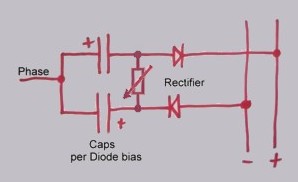
was working fine... til the smoke got out. Cheers Gill _Cairns, FNQ |
||||
| GWatPE Senior Member Joined: 01/09/2006 Location: AustraliaPosts: 2127 |
I will present some measured data. I was not able to measure the three variables at the same time with my instrumentation. I measured Windmill RMS AC output voltage between 2phases and the RMS AC current for 1phase. The 1phase RMS AC voltage is the reading between phases / 1.73. I measured the single phase RMS AC current in 1phase and the RMS AC voltage across the same phase capacitor. I measured the RMS DC current to the load and the RMS AC voltage between 2phases. Windmill furling at the higher power levels will distort this area somewhat. I was able to graph the data sets and interpolate from the graphs to produce a single data set that compared the RMS AC current per phase, the voltage across the capacitor and the RMS DC current to the battery with the same RMS AC windmill output voltage. The raw data and graphs are presented 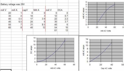
The single phase output voltage is calculated by dividing the voltage between phases by 1.73. This is the result of interpolations to compare the data sets. 
I am not prepared to interpret the data. It is clear that the caps are creating some phase changes with the current and voltage. I repeated the shorting of the caps during the testing and the maximum current to the battery peaked at 8.5A only. Dr Chalko could have saved us a lot of work by studying series cap configurations as well. Gordon. PS, I suspect that the caps are extracting more shaft power and some of that power is converted to additional battery charging current. There may be more power dissipation in the stator. This would not be good. Static testing would confirm this. become more energy aware |
||||
oztules Guru Joined: 26/07/2007 Location: AustraliaPosts: 1686 |
I give in Gordon, Why did you calculate the ac rms as phase voltage /1.73, if the machine is in delta?... for star I get it. I would have expected the delta phase voltage to be just the rms between phases. The total output current (AC RMS ) would have to halved though to see the AC RMS current in a single phase. However, as you measured a single phase only it should be correct.... but the voltage has me ? This would bring say the first reading up to 21v AC RMS X 1.414 = 31v DC... just over cut in volts... which makes sense to me. ( the sine wave looks good enough for 1.414) I'm lost again 
.........oztules Village idiot...or... just another hack out of his depth |
||||
| GWatPE Senior Member Joined: 01/09/2006 Location: AustraliaPosts: 2127 |
Hi oztules, my reasoning is 240VAC 3phase, like out of the grid. Between 2 phases you get 415VAC. The AC voltage on a single phase is only 240 though. I was trying to get an idea of the power that was seen. I had expected that the input power would have been the power per phase x 3. This was why my PS with the phase relationships being a factor. I have extrapolated the graphs from the data above to the maximum power that had been previously recorded. 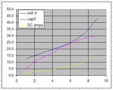
the x-axis is a reference mill ACamps for each dataset. The trends appear to be that the cap voltage is plateauing, the mill voltage is increasing and the output current is increasing. The AC on the rectifiers was increased slightly with increasing power 22-22.7VAC. The battery was able to hold the voltage pretty constant from 0-500W. This is not a perfect arrangement, but with a suitable test rig, a better understanding would be gained. On another note. The alternator will have a squared power output if the load impedance was a constant. ie double volts, then double amps, hence squared output power for a doubling of mill rpm. For a windmill to follow the wind power, the load has to increase as the voltage increases. The impedance has to fall. A capacitor has this relationship with frequency/rpm. Gordon. PS edit Cutin ACV for my battery is 22VAC or abouts, depending on battery SOC. become more energy aware |
||||
| oztules Guru Joined: 26/07/2007 Location: AustraliaPosts: 1686 |
Gordon, The grid 3 ph is star. This is so you can get 240v with neutral point grounded. If grid 3ph was delta, there would be no neutral point to ground...Power per phase can be IsqxR or ExI etc Total power is phase power X3 I was under the impression you are in delta with that setup, so phase to phase is your coil voltage. The another Note. I think Gill my be better at understanding the ac impedance of the coil with caps for resonance than me ( so would most people I think). But The square relationship with the alternator with rpm, holds true, even if you drag the impedance of the load down to load the alternator, ie volts down .. current up... same old same old.... but..... If the caps can decrease the AC internal impedance of the alternator as the Q goes up, then I think we can do better than squared... but only if the resonance can decrease the AC impedance of the alternator for us. So unless we can dynamically decrease the AC mill impedance with freq, we will never do better than square even if we use a theoretically correct MPPT, as this only changes the impedance of the load to match the alternators output.. or a matched resistive load.... If we run at around resonance, maybe the caps can do the impossible, and vary the internal impedance of the alternator. Can caps do this..... Gill?? ..........oztules Village idiot...or... just another hack out of his depth |
||||
| davef Guru Joined: 14/05/2006 Location: New ZealandPosts: 499 |
Sorry to chip in a bit late (and a bit off-topic), but I'd like to make some comments about polarised capacitors being reversed polarised: One of the few occupational hazards as an electronics engineer has been the odd time a (polarised) electrolytic capacitor got connected up backwards. If the reverse voltage was a significant percentage of the working voltage the "life time of capacitor" would be measured in milliseconds not days or years. Fortunately, I wear glasses . . . which if a capacitor had blown up in my face I would have protected my eyes. Ensure that polarised (electrolytic) capacitors never see a reverse voltage across them by the use of series diodes as per the last diagram on page 7. And make sure they are doing there job. (Not much point in the diode going short circuit because of in-rush current or who knows what). If firing up that big power converter for the first time wear safely glasses and keep well back. Also, recommend not doing it in the living room in case you have a mess to clean up! Back to your topic. |
||||
| GWatPE Senior Member Joined: 01/09/2006 Location: AustraliaPosts: 2127 |
Hi oztules, You should see by the data that the input AC power by the calcs was very large compared to the output DC power. This is what led me to think the current and voltage are really out of phase. 
I have made a test rig with a borrowed motor, a 2.2kW 3phase AC motor, thanks Bolty, a VFD, the motor is direct coupled to an 80 series rewired to 2S7P and some 8ohm 100W loading resistors. The VFD can be programmed to any motor frequency, 0-50Hz. The slip that occurs was ignored, as the output frequency was measured for each test. The VFD was set up without any feed back speed control. The 8ohm loading resistors were placed in star across the alternator output. I tested unloaded, loaded no caps, loaded + par caps, and loaded ser caps. The data was graphed so with interpolation a set of performance data at the same frequency could be generated so the effect of the caps at similar rpm could be made. This has not been done yet. The data and initial plots are given here. 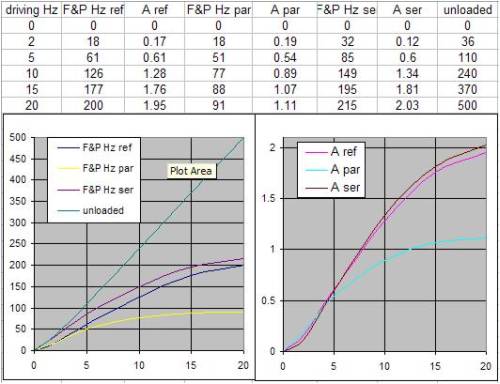
These tests were performed without rectification. In looking at the interrelationships, I see so many combinations to be investigated. The test was setup to sort of simulate wind loading effects. As the drive was ramped up, the load tried to slow the alternator. This is sort of what happens with a blade as it is loaded by the alternator and load. The parallel capacitors show a marked - change. The series caps show minimal + change. I will be checking on a battery as well. It is too early to make any conclusions. I have minimal components, so I will not be checking a range of capacitors. If I can get a rig set up with F-clamps a lump of timber and some electrical tape and plastic tube as a coupling, then I suspect there would be many others with some equipment who could be providing some test data as well. Gordon. PS Hi davef, the use of polarised caps back to back for AC use has merit. I use them for my testing. I do see a rise in temperature. Windmill today has been maxing out 550W on many occasions with average 150-200W. My cap bank is wrapped in electrical tape and the temp has risen a maximum of 16 degrees above ambient. These are 85 degree rated, but Jamicon make 105 degree types. The 200Hz AC is the problem. Apparently STD non polarised electrolytics are just 2 back to back in the same can. Apparently diodes are not neccessary either. become more energy aware |
||||
| GWatPE Senior Member Joined: 01/09/2006 Location: AustraliaPosts: 2127 |
I have run out of testing. If an normal AC induction motor is to be used for testing, it will probably need at least an 8x mechanical reduction gearing. Direct driving is useful for testing at the low power levels only. The 80SP tested has a much higher cutin. 300RPM into my 24V nom Battery. The capacitors had similar results to direct connection. I suspect that the higher cutin is a result of the lower coupling of the pole fingers as a result of the twisting to reduce cogging. Everything interacts unfortunately. My observations see a very rapid change in loading at the higher rpm. This is probably as the capacitors response approaches the tuned frequency. The performance matches the direct connection up to about 8A DC output. As the mill responds to the gusts, the current continues to increase with capacitors, whereby without, the current just flattens off. I may look at a drill press with 3phase drive to continue testing. Gearing may be the only way to use a std induction motor as a driving element. Time to look at hum removal. Gordon. become more energy aware |
||||
| Gill Senior Member Joined: 11/11/2006 Location: AustraliaPosts: 669 |
Oztules, I see the addition of series caps as providing 2 influences for the increase of power in ALL ac wind generators. 1. Power factor adjusting: This adjusts the internal impedance of the generator by the changing rpm(Fq). As coil voltage is set by the number of turns the coil voltage remains tied to rpm whereas the current is set by the internal generator impedance(resistive{wire resistance} and impedance{inductive and capacitive reactance}. Lower impedance raises the current. 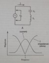 This 1st influence is set by the capacitors size(uF). I feel the selection of this value is most easily achieved by substitution just as Dennis did. It is not necessary to achieve resonance 'per se', as the curve will need be the best match for the wind curve. Here the coil Q dictates this curve but as that is not adjustable with our set F&P coil, we can leave that for the axial flux guys who wind coils to follow up further. With correct selection this achieves stage one of an MPPT function. 2. Current boost: I see this feature as being the result of the Back to Back electrolytic caps. I see them as providing a current boost similar to that provided by buck conversion and as such achieves partly or fully stage 2 of an MPPT function. I think provided the Fq stays below resonance the caps will charge within the 1/2 cycle, though discharge is faster and this makes a time where reverse bias potential is applied across the caps. I feel this current conversion could be controlled should failure become an issue for this reason. It is more prone at lower Fq. Of the two influences I see the first as simply a matter of finding a range of values for each F&P Series. It is the second with more unpredictable character yet I have not been able to draw any comment on this topic with my suggested tests. was working fine... til the smoke got out. Cheers Gill _Cairns, FNQ |
||||
| GWatPE Senior Member Joined: 01/09/2006 Location: AustraliaPosts: 2127 |
Hi Gill, The capacitors are not connected across each other. They are connected in series. The arrangement you present above presents a short in the caps. An electrolytic capacitor draws a lot of current when reverse biased. the caps I use are arranged + |cap1| - - |cap2| + I connect the two -v's together and the +v's are the connections in the wiring. I believe the extra current comes from the charge that is collected and discharged from the capacitors. This is seen as the voltage that appears across the caps that I measured and presented. The lowest impedance to discharge the cap when the polarity is reversed is through the rectifier. The process repeats twice in a cycle. The energy in a capacitor is proportional to the voltage across it squared divided by 2. The principle may only work with electrolytic caps. The output DC current seems to be correlated to the AC voltage developed across the capacitor. I am not sure of the general use for all alternators now. I have stated the need for the energy transferred by the capacitor to match the power of the windmill. The inductance and capacitance are inversely related. The tuning will be specific, yes, but usefulness will depend on a suitable capacitance to transfer enough power to be useful. Gordon. become more energy aware |
||||
| Gill Senior Member Joined: 11/11/2006 Location: AustraliaPosts: 669 |
Gordon, Thanks for putting me right on the Cap arrangement. That makes it harder. I can't see the sense in that at all. Still if it is working..... I'll leave you with it then. was working fine... til the smoke got out. Cheers Gill _Cairns, FNQ |
||||
| GWatPE Senior Member Joined: 01/09/2006 Location: AustraliaPosts: 2127 |
Hi Gill, I can only describe what was done. I am speculating as to the physics. I have provided some measured data. A full analysis is way beyond my resources. Maybe someone with venture capital could help out. Gordon. PS It is really hard to take measurements on a flying windmill that are objective. A test rig in laboratory conditions may be required. Do we really need to know why anyway? I am just happy to make use of the additional power I get. It sure beats having to put up a bigger windmill. become more energy aware |
||||
| oztules Guru Joined: 26/07/2007 Location: AustraliaPosts: 1686 |
Gordon..... I have a problem at this end I'm afraid. I calculate my inductance per phase at only 6uH from this formula L=radius^2 X turns^2 / 9 X radius + 10 X length Mean radius is 1.22 inches, length is 2304 inches, turns = 300..........6 uH It gets worse, as my operating freq is low then LC=25330/.000030^2 (mhz) ..... makes C approx. 4000000 uf. I think I will need a small wheelbarrow to carry the caps for testing.......... I'm out of contention for these tests I'm afraid 
.........oztules Village idiot...or... just another hack out of his depth |
||||
SparWeb Senior Member Joined: 17/04/2008 Location: CanadaPosts: 196 |
Yesterday I took some measurements that may be of interest in the discussion. My multimeter, "Meterman/ Amprobe 37XR" can measure inductance of a coil. Among the motors I've collected and converted, there is a Baldor 3-phase motor that I experimented on in the spring. I used the rotor from a different motor, temporarily installed magnets on it, and inserted it in the Baldor to do some tests. What I have is a 3-phase, 4 pole, 3hp motor with star connections, upon which I can measure phase inductance with no rotor, with the stock rotor, or with a rotor arrayed with permanent magnets. Here is what I measured: No rotor: 15.7 mH Stock rotor: 65 mH Magnet rotor: 27.8 mH With these numbers, particularly the one from the magnetized rotor, I worked out the impedance of the unmodified circuit (in Star) and then found the capacitance required to compensate. I used a highly simplified windmill as the basis, where simple open-circuit voltage is divided by winding resistance to obtain the current. Below is a graph of the generator's output. The red line is pure resistance, it's the baseline and would give the highest current output. The blue line takes reactance into account, and the growing impedance effectively caps the output of the windmill as the speed goes up. This like what I see in my operational windmill. I cannot make the curve agree exactly with my windmill output, however, because its output increases linearly up to 500 RPM before it flattens out. The blue curve is close enough for the purpose of seeing what's going on, I hope. The black dashed line adds up the impedances of the inductance, resistance, and capacitance in series on the windmill output. The capacitor has something of a counter-productive effect at low RPM, but once the windmill gets going (and the capacitor is helping it get started, in fact) the output really does get optimized at 300 RPM in this example. The optimization is VERY sensitive to the capacitor value. The values used in this case are L=35mH, C=7200uF, R=1.6Ohm, E=0.2V/RPM, and f=1Hz/30RPM (4 poles) 
Selecting a higher capacitor value, say 22,000uF, sends the resonant speed down to 200RPM, but using too high a capacitor value also cuts performance above 400 RPM. On the other hand, C=5000uF makes the resonant speed rise to 400RPM. Along with the higher resonant speed comes hampered performance at lower speeds. This is the detailed analysis, using MathCAD, a software program that does the arithmetic and algebra for you. I see a lot of power in these capacitors to counter-act the effect of inductance, even in motor conversions. Before putting too much faith in the math, however, let's bear in mind that the inductance in any motor is VARIABLE. All I can calculate here is a starting point. It will take plenty of trial and error. C may vary up or down by a factor of 10. The biggest capacitors that I have are 270 uF, so it will take some scrounging around to find anything 10 times higher, or 10 times as many. Like Oztules, I can't join the race just yet, either. Steven T. Fahey |
||||
| oztules Guru Joined: 26/07/2007 Location: AustraliaPosts: 1686 |
Sparweb, It looks impressive on paper, if you use a small booster at the bottom, you have a very good looking alternator. Also it depends on where you add extra resistance as to where your peak will be. A resistor in parallel with the capacitor will pull the freq down, or in parallel with the impedance will delay freq till later. 
I am orders and orders of magnitude away from your impedance, plus I have far too much unfetted output as it is at the moment... yesterday I had a short play, and was running over 2kw for a good bit of the time... just too much for me to handle for long before the batteries take off..... and it is still at ground level. Upping the efficiency is not at the top of my to-do list until I can use what I have. .............oztules Village idiot...or... just another hack out of his depth |
||||
| GWatPE Senior Member Joined: 01/09/2006 Location: AustraliaPosts: 2127 |
Hi oztules, the inductance of axial flux reminds me, you cannot saturate air cored inductors. I had said that inductance is the key, and the energy from the capacitive and inductive components must compliment. The axial flux is the opposite end of the spectrum to a large inductance machine. My axial flux mill has 17 turns per coil, the coils are a mean 1.25"x1.35" almost rectangular, and the wire length is 68" per coil and there are 11 coils per phase. There are 4phases. This amounts to a very small inductance. Resonant frequency would be very high, so I won't be investigating caps on it either. My suspicions on caps helping a very select group of alternators may be true. Hi sparweb, The output current for inductance only you provide does not fit the observed behavior of a windmill. Is this because you have simulated with a resistive load and not a battery? IRW on a battery, I see current limiting and not a negative exponential drop off of current. How do the measured values I have given compare with your simulator predictions? If you need specifics, please advise? RFSim99 rounds the inductance to 1 sigfig. It gives a frequency pole at 11Hz with the data you provided. This is 330rpm with your alternator. With my mill, 230uF works well. From your calcs I can reverse engineer and calculate that the 100S in delta has an inductance of about 2.5mH. The number of turns is known for all F&P stators and can easily be calculated for all rewires. Ecoinnovation provided a table somewhere. The various inductances could be estimated and then the capacitor values calculated. The best units in various rpm ranges could then be tabled. Gordon. become more energy aware |
||||
| SparWeb Senior Member Joined: 17/04/2008 Location: CanadaPosts: 196 |
Gordon, I used the reactance calculations that are the basics of AC circuits. I know you don't want to "go back to school", but if you want to know more, here's a great primer on the use of the formulae: All About Circuits I agree, having done the math myself, that if you have one mill with 15 times the inductance as another, then the capacitor values required to optimize it will also be 15 times greater. One must be careful making this assumption, however, because the frequency/RPM ratio also comes into play. That mill requiring higher value capacitors to go with its higher inductance would also need to have 1/15 of the frequency per RPM, or else the speeds will not be matched. Your FP has how many poles? About 60 right? Bang on 15 times more than my 4 pole, which is darned lucky, isn't it!? 
I plugged some of your numbers into my calcs, and 430 RPM did, indeed, fall out of the bottom. Looks good so far! 
Oztules: You just keep working on things to do with your kW's of excess power and we'll keep working jealously on our miniatures! 
Steven T. Fahey |
||||
| GWatPE Senior Member Joined: 01/09/2006 Location: AustraliaPosts: 2127 |
Hi sparweb, What happens to the AC voltage across the capacitor at resonance? I have measured an increasing AC voltage with increasing power. Does this correspond to the theory, or does the inductance vary similarly with increasing mill rpm, to counteract things. Gordon. become more energy aware |
||||
