
|
|
Forum Index : Windmills : Testing Capacitors
| Author | Message | ||||
herbnz Senior Member Joined: 18/02/2007 Location: New ZealandPosts: 258 |
Its our little secret to confuse the natives lol reactive power that is inductive is power that goes to charge magnetic fields on the increasing side ac cycle then is returned to cct on the decreasing side as they collapse 90 degrees out step with power in resistor. no need for supply from the source hence no watts, wattless. Yes if the current suppling this is via resistance in wires I^2 R losses are there. hence we use caps that do the same but at opposite times to supply this necessary magnetising power (VARS)locally rather than via wires. |
||||
| herbnz Senior Member Joined: 18/02/2007 Location: New ZealandPosts: 258 |
Steven If you get what you call failures like above please can you go ahead and document there is much more to be learned from failures than success usually. Herb |
||||
| KiwiJohn Guru Joined: 01/12/2005 Location: New ZealandPosts: 691 |
[KiwiJohn walks quietly away shaking his head and looking for old text books]  |
||||
fillm Guru Joined: 10/02/2007 Location: AustraliaPosts: 730 |
Herb , If something doesn't work , theirs no way in the world I am going to waste time on documenting the failure , it is simple 50Uf caps didn't work if some one can come up with a equation for how to select the right cap for a given voltage and stator, would be amazing.. PhillM ...Oz Wind Engineering..Wind Turbine Kits 500W - 5000W ~ F&P Dual Kits ~ GOE222Blades- Voltage Control Parts ------- Tower kits |
||||
SparWeb Senior Member Joined: 17/04/2008 Location: CanadaPosts: 196 |
Hi, I wish I knew how to edit or correct stuff - I really did get the terminology mixed up. VARs is the proper unit of reactive power. Now what I don't understand is the bridge between the mechanical power and the electrical power. I thought that in a system where Mechanical power is INPUT, such as a generator, the Apparent electrical power must be fulfilled if the power factor is not =1, while if an electrical source is the INPUT, such as a motor, then only the True power can be OUTPUT, but the Apparent power is the INPUT when power factor is not =1. I expect to be wrong on this. I'm sorely lacking in textbooks (like KiwiJohn). Phill, I won't go chasing down the rest of the test data (for the cap corrected tests) until I can get my head on straight. I'm content to be wrong if I can learn something from it. Takes time for the lesson to sink in... still a long way from making predictions... ...Seems I also have to go read the FP&PE thread, too... Steven T. Fahey |
||||
| GWatPE Senior Member Joined: 01/09/2006 Location: AustraliaPosts: 2127 |
Hi sparweb & herb. The F&P@PE thread, was where I started documenting my stuff and testing results. Things have moved on a lot. I have been liasing with Phill re some cap testing. The 50uF episode you mention and phill has been caught up in came about during the first testing phase. Phill doubted the caps could work as the outputs were so bad and things got hot. We had many phone linkups to confirm wirings were as per p15 cct on the other thread. I decided that series resonance was the culprit, and the series80S was not going to work with the loading available. The series80 rewire 2s7p was where to go next. The data used in the graphs I provided will be published when a second test run is done. There were some outliers, so I felt the raw data would be confusing and if used in other number crunching, that this could discourage future analysis to do it again with new data. Phill will be back from work soon, so the wait should not be too long. Gordon. become more energy aware |
||||
| GWatPE Senior Member Joined: 01/09/2006 Location: AustraliaPosts: 2127 |
Readers may be interested in the winding resistance of a rewired series80 2s7p being around 0.2ohms per phase. This would account for the higher performance of this configuration in testing in delta and 48V. Gordon. become more energy aware |
||||
| herbnz Senior Member Joined: 18/02/2007 Location: New ZealandPosts: 258 |
hi Been studying Phils results in detail. The indications I have had from previous reports is that caps increase the natural current limit ( in my mind current limit is caused by the demagnetising effect of the stator current )this has been puzzling me. In the past I have used amount of the contribution of the dc output curent as a indication of the ampere.turns in each stator coil, amore correct way would be to convert to actual current flow. Using this allows me to do quick calcs. My past tests indicate limiting occurs approx between 150 to 200 amp turns. now crunching these figures delta 48v no limiting output 400w .68a/pole 136amp turns - caps give increase star 48v limiting output 250w .74a/pole 148 amp turns - caps no increase delta 24v limiting output 250w .85a/pole 170 amp turns -caps no increase star 24v limiting output 150w .9 a/pole 180 amp turns - caps no increase this is showing caps will change chars below limiting and can be used here but runaway will occur just the same after about 150 amp turns (this is lower than what i had tested in the past but results here) On hydros and fixed units caps have little use, as confirmed by Gill's results, i always use my bank for fine tuning but never leave them in. However on the variable wind mills we must be able to set up to get close to a chars that match utilising the fact that caps automaticly change with frequency. Gordon i realize you dont accept my methods or theory but what i would ask is can you give me a set of figures that show the power available from a mill at say 100,200,300,etc rpms i know its When my testbed is avaliable i will set up one to this chars. Herb |
||||
| GWatPE Senior Member Joined: 01/09/2006 Location: AustraliaPosts: 2127 |
Hi herb, You can appreciate that the readings change very quickly on the windmill. I will attempt to get some rpm/amps/volts readings. I have to convert my windspeed to voltage sensor to an rpm to voltage sensor, so I can record at a useful rate with my 4 channel logger. This will require a change to the loading, to remove the battery from the equation as well , so all power will be recorded into the one loading. I am still finishing my wooden blades, and trying to save some fruit from the birds, so this may take some time. I will need to wait for some stronger winds as well. I don't thing acceptance of theory is right. I just have not seen the theory account for the measured readings. Gordon. become more energy aware |
||||
| herbnz Senior Member Joined: 18/02/2007 Location: New ZealandPosts: 258 |
I dont need readings off your mill actually just need what is the ideal chars for gen. The white graph is enough i suppose. let me confirm tho to see if i got my facts right. power from the wind is proptional to the cube of the windspeed. TSR is the ratio of windspeed and tip speed. it is ideal to keep a constant TSR therefore we want a gen that has a power output proptional to rpm cubed. btw one gen i know that is ideal for this is separatly excited series gen has this been used ? A Permanent Gen in its natural state can only have voltage directly proportional speed therefore power output proptional to speed ^2 (power prop v^2 ) herb |
||||
| KiwiJohn Guru Joined: 01/12/2005 Location: New ZealandPosts: 691 |
Herb, I believe you are right on all counts including the need for a power output to increase faster than RPM, so I have opened another topic on that! |
||||
| fillm Guru Joined: 10/02/2007 Location: AustraliaPosts: 730 |
Hi All , I have finally put the mill back up and have used a dual stator set up in 2 x 80s 2s 7p with one in star and 1 in delta , both have the caps and voltage doublers and std rectifiers in parallel and twisted poles approx 10deg, as you can see from the pic of the cabnet at the base it is a bit of work to get it all set up , especially for someone who is a bit challanged in the electricial finner points 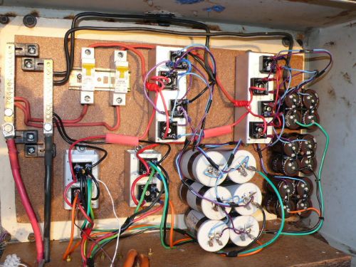
It went up last tues at 2.30pm in a very light 10 to 15 klm patchy breeze and the moment it started turning it sounded completly different from any of my previous mills , The quad ( would not have been turning ) The dual Neos wouldn't have looked at at spinning , my first dual , which are the same stators fitted here had to have the bridge recs in series and the output was dismal , BUT this is the WINNER buy a MILE , instantly the amps were sitting on 1 to 3 and even when it died down to just moving the leaves I was still getting .2 to 1 amp into 53V ... As Gordon has said " POWER WHERE THERE IS USUALLY NONE " A couple of slight puffs came through of approx 20 to 25klm and the amps instantly shot to 12 ( 600watts ) for a few brief moments and with in 4 hrs 225 watt/hrs were accumulated on the piclog , the next day was even more dismal for wind and 250w/hrs were accumulated , 1/2 Kw where all my other mills would have been lucky to do 100W/hrs.. As was posted in the graphs Gordon did from my Lathe tests on output from a dual in this config it seems to be performing exactly as the power curve says , cut in is @ 100rpm and just keeps going up in relation to the wind .. The blade dia is 2.850mt and are the same blades that hit the deck on the Quad , cut down and reshaped and I feel they are still to big for this set up as the tips are making a fair bit of noise at higher rpms . I am unable to publish the data from the piclog at present as there are problems with the Rpms as the AC pulse is all over the place and very high voltages , due to the Caps hopefully this will be sorted out soon , I also don't have a annemometer as this was destroyed with the quad failure , hopefully soon it will be all working better than before as I now have upper guys and the A/C leads running through the pole and have made provision for the annemometer to mount just below the blades on the pole . In summing up to this point .. I must give credit to Dennis L for starting the cap testing and Gordon for his tireless efforts with the Caps and Doublers etc and Brian for the twisting poles to minnimise clogging . As stated many times over IT DOES WORK!! and I don't really care how it does it and how the capacitor works or what happens to the flux before and after etc ..etc ..etc.. as many out there seem to want to debate the finner details . I am just over the moon with watching the results on an amp/watt meter going back into the grid inverter is enough for me ,and of course to keep testing and posting results ...Regards to all... PS.. The big gap behind the rear rotor was for the Quad Stator which needed 6 blades to even try and match the output of this mill , #2 is on the way and it wont be "THE BEAST"... 
PhillM ...Oz Wind Engineering..Wind Turbine Kits 500W - 5000W ~ F&P Dual Kits ~ GOE222Blades- Voltage Control Parts ------- Tower kits |
||||
| KiwiJohn Guru Joined: 01/12/2005 Location: New ZealandPosts: 691 |
Excellent work Phill, you quite right to be proud of it. |
||||
| brucedownunder2 Guru Joined: 14/09/2005 Location: AustraliaPosts: 1548 |
Well done Phill. I'm doing maintenance on my rig ,,hopefully get it back up soon and do the cap's thing.. Bruce Bushboy |
||||
oztules Guru Joined: 26/07/2007 Location: AustraliaPosts: 1686 |
Very nice looking set up there Phill. It works and that s the key thing. Gordon has done a great job testing out different configurations, and it looks like it has culminated in a very usable system for you. The doublers seem to fill the gap of electrickery quite nicely, and this is a good thing for the pwm challenged. It means a simple inexpensive bulletproof system is only a wiring job away for the F&P'ers. As with all the things you do, it looks the part as well. Nice work........ oztules ps I'm still none the wiser as to how the caps work in back to back, and the jury is still out on the exact mechanisms that make the caps work on the mills..... but I guess Dennis is right... who cares so long as it works. I have learn't an awful lot through this "debate" process, but it is still a mystery of sorts.... sigh.. Village idiot...or... just another hack out of his depth |
||||
| KiwiJohn Guru Joined: 01/12/2005 Location: New ZealandPosts: 691 |
The workings of the capacitors in this application are a mystery to me too, but then so are a lot of things, my wife says I dont even know how the toilet set works.
However, do we have a comprehensive schematic of a F&P mill incorporating capacitors anywhere? |
||||
| GWatPE Senior Member Joined: 01/09/2006 Location: AustraliaPosts: 2127 |
Hi Kiwijohn, There is a schematic that I posted for the capacitor doubler on p15 of the visual effect of caps thread, but I will include a link here. cap cct The doubler is connected across the normal bridge rectifiers. This is a parallel arrangement. The wild AC from the normal rectifiers inputs connects to the sets of caps in the doubler. The rectified outputs from the doubler connect to the DC lines to the load. It is important to NOT leave out the normal rectifiers. Cap values of 50uF to 250uF 240VAC, or equivalent continuous rating will work for a 24, and 48V setup. larger and smaller cap values will decrease doubler effectiveness. I have no testing for 12V system. Gordon. become more energy aware |
||||
| Gizmo Admin Group Joined: 05/06/2004 Location: AustraliaPosts: 5019 |
What I plan to do in the next few weeks is put together a page about the caps. We have a couple of combinations that work ( 100 series for 24v, split 80 series for 24v ), so its something that can be documented and the results replicated by anyone. As other working combinations come to light, I'll add them to the page. I would still like to see an option for the 12v users, even if it involves a 24 battery bank efficiently regulated to 12v. A lot of people, like me, use 12v and have 12v inverters. Glenn The best time to plant a tree was twenty years ago, the second best time is right now. JAQ |
||||
| KiwiJohn Guru Joined: 01/12/2005 Location: New ZealandPosts: 691 |
Glenn, excellent idea, putting such a page together. Thanks Gordon, I wasnt sure that the page 15 schematic was the current convention, ('groan') there has been so much discussion and I sort of lost track! Meanwhile, I am nutting out a scheme that might be of interest to low voltage users, of course it will most likely get rubbished as soon as I post it!  |
||||
| GWatPE Senior Member Joined: 01/09/2006 Location: AustraliaPosts: 2127 |
Hi kiwijohn and Gizmo, The 12 volt arrangement should only require 2 of the same capacitor arrangements used on 24V. There is 2x the current at half the voltage. The capacitor sizing is mostly related to power [current] transfer. A certain size capacitor can handle a certain amount of current. If you use 2 sets of caps that work at 24V, rather than a single large cap, then there is more chance that the power handling [amps] will be doubled. My latest testing showed only a 10% change in power output for a 4x change in capacitance, either side of the 100uF value on the doubler on a F&P 24V system. This suggests to me that the AC coupling, removing the heavy loading caused by a battery is probably the most significant aspect. I suspect that the additional current I have measured into the battery is supplied by the additional emf produced by the alternator. I have measured 20AAC in the stator as well, so it is likely that additional power is also consumed in the stator as heat, rather than rejected by the inductance. I will speculate here by saying that it is possible that the only application that will benefit from the cap arrangement is a windmill, because the alternator will not necessarily be more efficient. Gordon. become more energy aware |
||||
