
|
|
Forum Index : Windmills : Testing Capacitors
| Author | Message | ||||
| KiwiJohn Guru Joined: 01/12/2005 Location: New ZealandPosts: 691 |
Hmmm, a 250% increase in output is certainly much more than just improved efficiency. There is something happening here that I dont understand as apparently addition of capacitors somehow modifies the mill so that it extracts more energy from the wind and if that is the case Phill's lathe tests may not lead us down the path towards the knowledge we seek. 
As always, IMHO. |
||||
oztules Guru Joined: 26/07/2007 Location: AustraliaPosts: 1686 |
It's about what I would expect Gordon. The current line represents a fair display of emf-soc shape of an unloaded voltage curve. It is slightly behind the voltage rising wave front as no curent can flow until soc is reached.. except charging up of plates in the caps before soc is reached (probably lost in the noise at 0v till soc. It may also be that chemical changes in the batt plates lag slightly as well (speculation). The trailing edge of the current curve appears to hold up until v approaches 0, so the cap must sustain the current curve for a very short time... following the voltage down slower. ( I assume we need to lift the v curve up a bit to match the amplitudes...). The voltage seems to plummitt as soon as soc is reached on the trailing wavefront...this is probably the last gasp of the cap... holding the soc up for as long as it can, before trailing off the current... from the cap. Of interest, is the top portion of the voltage curve. It tells me that the caps give a softening of the load impedance, allowing the V to increase above soc, and so allow the blades a bit of leeway. This extra leeway will express itself in better tsr and higher emf. Way to go Bryan.... windy as all .... here as well. Mill is stopped as the car is charged, and too windy to drive it 
Will be interested in the figures. Edit: 1/1/09..... still too windy, car still fully charged, wind passing by without me extracting some worth out of it  probably wasting 1.5 to 2kw....... probably wasting 1.5 to 2kw.......
.........oztules Village idiot...or... just another hack out of his depth |
||||
| GWatPE Senior Member Joined: 01/09/2006 Location: AustraliaPosts: 2127 |
I have some more pics, but will post on the visual effect of caps thread. Gordon. become more energy aware |
||||
fillm Guru Joined: 10/02/2007 Location: AustraliaPosts: 730 |
Hi All, Sorry I missed all the action , have been for a hot air balloon ride today and had to get up at some ungodly hour ,and then came home and hooked straight into some more testing with caps . Thanks Peter and everyone for doing the number crunching , as you can see the computer is not my best friend , but good to see great team work and good advice comming out of the test for all to benifit from.. I sent Gordon a swag of test results tonight done today on 24v and 48v using the caps&doubler and standard bridge rec in parallel, hopefully he can present it a lot better than I can .. PhillM ...Oz Wind Engineering..Wind Turbine Kits 500W - 5000W ~ F&P Dual Kits ~ GOE222Blades- Voltage Control Parts ------- Tower kits |
||||
SparWeb Senior Member Joined: 17/04/2008 Location: CanadaPosts: 196 |
[quote] ... A series80 has a single coil wire resistance of approx 6ohms. Gordon. [/quote] Thanks Gordon, but that surprises me! The "80" has 42 coils on it! Did you mean "single phase" resistance of 6 Ohms? Steven T. Fahey |
||||
| GWatPE Senior Member Joined: 01/09/2006 Location: AustraliaPosts: 2127 |
Hi sparweb, This is approx single phase resistance of a std unmodified series80 F&P stator. The number crunching of Phills data is almost finished. I will run the spreadsheet back to Phill. There is a lot of data, and graphing of multiple sets on the same axis will confuse things. I have prepared many comparison graphs, including some normal dual stator combinations, and how these change with doublers. I won't spill too many beans yet. Gordon. become more energy aware |
||||
| GWatPE Senior Member Joined: 01/09/2006 Location: AustraliaPosts: 2127 |
Hi readers, Phill has asked me to publish the first set of graphs. This will give some idea of typical 80SP rewire outputs into 24V & 48V systems with star and delta configurations with and without a capacitor doubler. and what can be achieved with a dual combination as Phill is planning to configure. This is the first of a series of testing. These are not laboratory std results, but all measurements were done on the same day, in the same sequence, with the same instruments and the capacitors used in the doubler were 50uF non polarised type of > 400VAC ratings. The graphs are annotated and should not require explanations. These graphs only test one value of capacitance so far, for a doubler combination only, in parallel with existing rectifiers. 24V Star 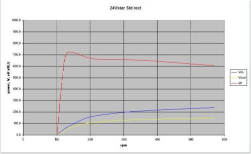 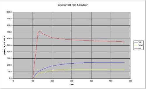
24V delta 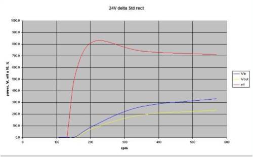 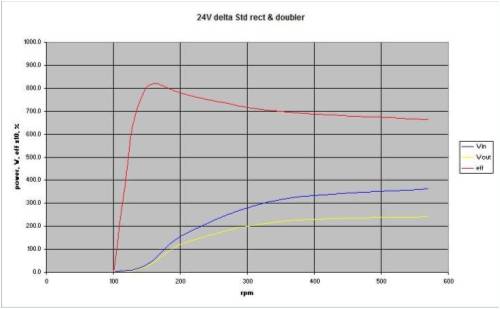
48V star 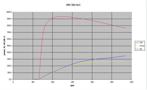 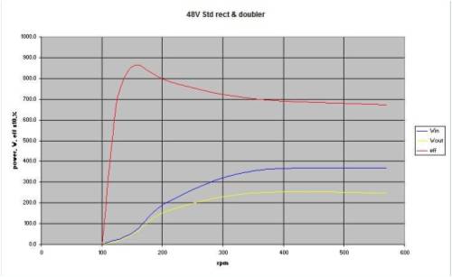
48V delta  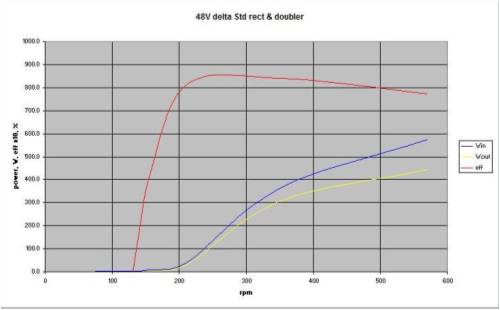
48V dual, star and delta 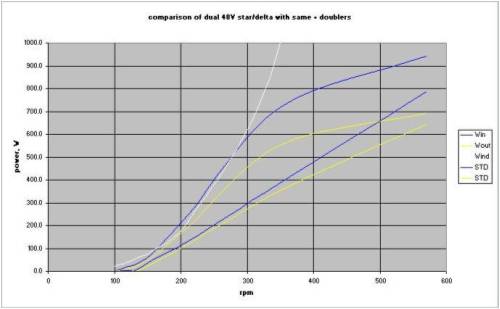
This last graph shows 2 sets of data. The lower sets, straighter lines are for a usual dual with a star and a delta configuration. the upper set that closely follows the white line [approx cubic wind energy curve] are for the same configuration with capacitor doublers across each stator as well. Gordon, for and on behalf of Phill. PS edit: The cutin rpm is not accurately known as the rpm cannot be precisely adjusted. This will be looked at in future testing, to confirm the small differences with the doubler to cutins. become more energy aware |
||||
| fillm Guru Joined: 10/02/2007 Location: AustraliaPosts: 730 |
Thanks Gordon for doing all the graphs and calcs with the data I collected , I will rase one concern I have that we talked about and that is the Open circuit voltage hith the Caps and doubler , as I took readings every step the higest it hit was 392VDC at 500+ Rpm and the "Stored Energy" in the Caps when discharged was a very scarry spark!!! BE CAREFULL IF YOU ARE GOING TO USE CAPACITORS!!!! And the should not be left open at the bottom of a windgen tower for some one to come in contact with .. As you can see from the last graph my Quad Stator is going to be shelved and I will be going back to a dual and using Caps & Doubler .. I will be running a second set of tests over a broader range of speeds when I get back in 7 days and hopefully can get hold of some different cap sizes to trial PhillM ...Oz Wind Engineering..Wind Turbine Kits 500W - 5000W ~ F&P Dual Kits ~ GOE222Blades- Voltage Control Parts ------- Tower kits |
||||
| KiwiJohn Guru Joined: 01/12/2005 Location: New ZealandPosts: 691 |
Gordon, Phill, great work there! However I must confess to be rather dumb, could you please explain what the red, blue, and yellow traces represent? I cant make out what the little box says on my display. |
||||
herbnz Senior Member Joined: 18/02/2007 Location: New ZealandPosts: 258 |
Gordon Phill Many thanks for your efforts John I blew the images up and you can read them. Red eff yellow Wo Blue Win Many questions I would like to ask but as At this time I am a armchair observer I will keep brief To change from 24 to 48 volts were you changing the batteries or was there another form of load ? Would it be possible to show the cct actually used of the doubler there has been a few versions publised ? Herb |
||||
| GWatPE Senior Member Joined: 01/09/2006 Location: AustraliaPosts: 2127 |
Hi herb, the load for 24V, was a 2 x 12V @ 200Ahr [approx] Pb-acid batteries in series. The 48V was a commercial 48-24V DC-DC converter, as used in trucks etc, connected to the same battery. The battery voltage was maintained at close to 26V with an inverter and loading. The cct was that provided on p15 of the visual effect of capacitors link to cct thread, 2/12/08, using 6 x single AC, non polarised capacitors with associated rectifiers, instead of the 12x back to back polarised electrolytic DC capacitors and associated rectifiers. All the graphs were similar layout. There was efficiency x10 as a % plotted with the input power and output power in the first 8 graphs. The final graph indicates the loading curve that can be obtained with a dual stator combo. There is no reason that for 24V, that a single series80 stator wired as 14p, with half the coils connected in star, and half in delta, with normal rectifiers and doublers as well; would perform as well as the series80 2s7p at 48V. As Phill, has pointed out, high voltages can present with an unloaded system and capacitors, so treat all connections as lethal, even on a 24V system. [code] 24V RPM dc/oc-s/br dc/oc-dbl star 100.0 46.7 63.9 star 122.0 57.0 78.0 star 131.0 65.0 89.0 star 156.0 86.0 106.0 star 212.0 101.0 133.0 star 350.0 147.0 235.0 star 571.0 270.0 370.0 [/code] These are some serious voltages stored on the 50uF caps at the higher rpm. Take care out there with unloaded systems with testing. Gordon. become more energy aware |
||||
| Gizmo Admin Group Joined: 05/06/2004 Location: AustraliaPosts: 5024 |
It might be an idea to place a 100k resistor across each cap. This will bleed off any lethal charge within several seconds. Maybe on any future circuit diagrams we include the resistors as a safety measure. Glenn The best time to plant a tree was twenty years ago, the second best time is right now. JAQ |
||||
| Gizmo Admin Group Joined: 05/06/2004 Location: AustraliaPosts: 5024 |
It may not be practical, but I would be interrested in some tests on a 12 volt system. There are 12v systems out there, and a lot of 80 and 60 series stators, the 100 series are becoming rare. Glenn ( poor old 12v system user ) The best time to plant a tree was twenty years ago, the second best time is right now. JAQ |
||||
| GWatPE Senior Member Joined: 01/09/2006 Location: AustraliaPosts: 2127 |
Hi Glenn, The testing suggests that even a series80, 14p has too many turns for 12V. This would be similar to the 24V graphs in shape and power outputs with rpm. Series caps, that would reduce the loading at low rpm, coupled with a doubler, or tripler may be a better option with a series80 rewired to 14p. You will have to test this yourself though. The kiwi rewind may still be the best option for 12V, if series100 stators are scarce. A chinese windmill would look like a good option. Gordon. become more energy aware |
||||
| SparWeb Senior Member Joined: 17/04/2008 Location: CanadaPosts: 196 |
Thank you Gordon for the extra info. Now I have been able to break the data down (in my own quirky way), and there's something I'd like to put in, now: 
Because a lot of information was provided, I was able to make an analysis of all of the power inputs and outputs. I started with the mechanical power. The force on the lever, times its length gives torque. Torque times rotational speed gives power. For example: At 357 RPM, the Star input force 710 grams x g = 6.96N The arm is 0.846 meter, thus Torque= 7.0 N*0.846 m=5.9 Nm When turning at 357RPM, or 37.4 rev/sec P_in= 5.9 * 37.4 = 220 Watts The same is repeated with the 45 grams to find the power lost to friction and magnetic hysteresis in the iron. P_iron = 14 Watts The output power is pretty easy: 52 V * 2.5 A P_out = 130 Watts Knowing the phase resistance of the stator (in Star) is 6.0 Ohms, then the loss to copper resistance is: 2.5A * 2.5A * 6 Ohm * 1.73 (the square root of 3=1.73) P_copper = 65 Watts So if it takes 220 Watts to turn the generator, presumably those 220 Watts must go somewhere, do something... 14W + 130W + 65W = 209W Where is the missing 11W? A little bit of power may be lost in the rectifier... 1.5V * 2.5A = 4W ...and there's certainly some margin for error in the data, but the shortfall is consistent through all data points. I believe it is lost to "reactive power". Since everyone has been talking about inductance in these F&P's, then it would be a certain amount of reactance that is being counter-acted by the capacitors. Analysing AC circuits with out-of-phase power is a little tricky. I'll try it with a small diagram, but you would be best to look it up on a reference like "All About Circuits", where there is a lot of good explanation. _ \| Using trig, any side of a triangle can be found if you know the other two. Reactive power is 90 degrees to the real power component. A mechanical system, on the other hand, is loaded by the "vector sum" of the components. Usually that's done with the "sum of the square of the sides" approach, and it will work here. The hypotenuse is the mechanical power input (220W) The long side is the sum of the known power demands (209W) The third side is sqrt(220^2 - 209^2) = 69W I have graphed out the reactive power along with the other data for the Star and Delta tests. I don't have the data for the capacitor corrected tests. Ultimately, if there is going to be any "science" to sizing the capacitors, a power analysis like this one can be done to find the amount of reactive power to be counteracted by the capacitors. More tests will help demonstrate that empirically. Steven T. Fahey |
||||
| KiwiJohn Guru Joined: 01/12/2005 Location: New ZealandPosts: 691 |
Deleted by me, while I read some more books! 
[Later] OK, I looked at the books again, 'reactive power' is as far as I can understand another way of expressing the losses associated with a less than perfect power factor and refers to the losses incurred when current flows in and out of a reactive component (capacitor or inductor). I think the current and voltage graphs we have seen indicated such a good power factor that it cannot explain the level of reactive power shown in these graphs. |
||||
| GWatPE Senior Member Joined: 01/09/2006 Location: AustraliaPosts: 2127 |
I have added some comments to the F&P@PE thread for sparweb and others to consider. This is not directly related to cap testing. Gordon. BTW: I have a problem with the delta graph. If you add the power output to the reactive loss and the friction loss, then this is greater than the power input at the 300W and 400W input power level. also When turning at 357RPM, or 37.4 rev/sec should be 37.4 rad/sec become more energy aware |
||||
| fillm Guru Joined: 10/02/2007 Location: AustraliaPosts: 730 |
Steven , Is the data you have used to do these calculations and graphs , are they the figures I posted a week or so ago , if so they are for a unmodified 80s stator and were done to use as a base for any improvements that can be made with caps , twisting poles , bearing seal removal and even neo hubs .. The graphs have a lot to say and very well presented but when I put the 50Uf caps on a unmodified stator it was a total failure , from your caculations can you work out the correct cap size for this stator? PhillM ...Oz Wind Engineering..Wind Turbine Kits 500W - 5000W ~ F&P Dual Kits ~ GOE222Blades- Voltage Control Parts ------- Tower kits |
||||
| herbnz Senior Member Joined: 18/02/2007 Location: New ZealandPosts: 258 |
Steven Reactive power is VArs not watts it is Vars do not require input power so have no bearing on the watts in. They are refered to as wattless power. Nothing in the info supplied indicates that there is or is not VARS present you are assuming input is apparent power its true power. Herb |
||||
| oztules Guru Joined: 26/07/2007 Location: AustraliaPosts: 1686 |
.... do you mean wattless current or wattless volts?... wattless power seems to be contradictory sort of. lost on this a bit (again) .........oztules Edit, I was pulled over the coals by Danb for referring to wattless power in IRC once and didn't forget it, now I look it up, and it is really used by the you electrical engineers..... sorry for the interjection (although I notice that reactive current in a resistive circuit can lead to real power loss. Village idiot...or... just another hack out of his depth |
||||
