Notice. New forum software under development. It's going to miss a few functions and look a bit ugly for a while, but I'm working on it full time now as the old forum was too unstable. Couple days, all good. If you notice any issues, please contact me.
kingw Newbie Joined: 07/03/2010 Location: United StatesPosts: 23
Posted: 04:19pm 10 Mar 2010
Copy link to clipboard
Print this post
As a fun project I am going to build an anemometer. A cross between the Easter Egg (any better materials suggestions vs. plastic Easter egg halves are welcome) and the bicycle computer one found on otherpower.
I have a wired bicycle computer module and I�ve been thinking about the best ways to extend the wire. I wonder if rewiring it with a longer wire would throw off calibrations or be too much resistance for the little 3 volt (CR-2032) battery.
That way I could have the computer head unit in the house and the anemometer outside, but we�d be talking about a fair bit of wire there.
The other option would be to just run the computer down to the base of the pole and build a little outdoor housing for it. But wouldn�t it be fun to be reading inside and glance over to look at the wind speed?
Any suggestions?
-kingw
bobshau Newbie Joined: 22/11/2009 Location: United StatesPosts: 27
Posted: 12:42am 11 Mar 2010
Copy link to clipboard
Print this post
I am using a DIY anemometer that I made similar to the one you describe: Three Easter egg hemispheres; hard-drive bearing; bicycle speedometer/computer powered with the CR-2032 battery, and magnetic actuated reed switch from Radio Shack. The computer readout was located in the house about 450' from the anemometer coupled by two 22 AWG conductors. Worked great for several months until water penetrated the insulation in the wiring and shorted the signal. The readout is now located in the instrumentation shack located about 50' from the anemometer. Apparently, the reed switch signal to the computer doesn't draw much current and dosen't cause significant voltage drop to interfere with performance.
Blessings and peace.
BobBobS
Downwind Guru Joined: 09/09/2009 Location: AustraliaPosts: 2333
Posted: 01:57am 11 Mar 2010
Copy link to clipboard
Print this post
I have build a few now with HDD motors as bearings and old printer parts for the photo interrupter and a 08m picaxe to count the pulses and transmit it wireless to the house that another 08m Picaxe receives the signal via the 433mhz receiver.
The picaxe sends the data to a computer to be logged.
As for your long wire to the house..1 it could be made a wireless link....2 why dont you mount the aneomometer on a pole off the roof of the house then the wiring run will be shorter.
It would be best to have the meter where you would read it often and loose a bit of accuarcy then have it mounted somewhere you view it once a week.
Pete.Sometimes it just works
birdhouse Regular Member Joined: 27/01/2009 Location: United StatesPosts: 63
Posted: 02:16am 11 Mar 2010
Copy link to clipboard
Print this post
kingw-
would it work to use the standard wire that comes with the bike speedo and mount the unit on the pole, then use binoculars to get the reading? that would make it really easy and accurate!
birdhousei pee more than once before flushing, and don't have to flush at all up at the ranch!
kingw Newbie Joined: 07/03/2010 Location: United StatesPosts: 23
Posted: 02:18am 11 Mar 2010
Copy link to clipboard
Print this post
Roof mounted for sure Pete. I might be able to just come straight down through a vent hole through a light fixture and into the living room. Now wouldn't that be nice? I've got my HDD motor and the bicycle computer is en route. Should be posting pictures this weekend (so long as I don't get swamped!)-kingw
kingw Newbie Joined: 07/03/2010 Location: United StatesPosts: 23
Posted: 02:19am 11 Mar 2010
Copy link to clipboard
Print this post
mm no binoculars for me. that sounds like more work than having it cozy in the living room.-kingw
Downwind Guru Joined: 09/09/2009 Location: AustraliaPosts: 2333
Posted: 03:09am 11 Mar 2010
Copy link to clipboard
Print this post
If you can get the wiring into house near where to computer is or can take a laptop to the wiring then it would be real easy to use a 08m picaxe to data log the wind speed to the computer.
You still could use the bicicle display as well.
The signal in will need to be under 5 volts.
I could help you with the program for a picaxe if you needed.
Just a thought and might change where you mount the aneometer.
Heres a shot of my last one i built with easter egg moulds for cups.
Pete.Sometimes it just works
Downwind Guru Joined: 09/09/2009 Location: AustraliaPosts: 2333
Posted: 12:20pm 11 Mar 2010
Copy link to clipboard
Print this post
heres a photo of the internals showing the photo interupter used out of an old bubblejet printer.
.
You can see the amount of interrupts it has per rev. by the shaded area on the clear plastic disc being made up of interrupt lines.
Most systems with 1 or more targets (sensors) per rev. is next to useless in low wind speeds and as most bicycle computers only have 1 target per rev. I question what sort of reading they give in light winds.
PeteSometimes it just works
Tinker Guru Joined: 07/11/2007 Location: AustraliaPosts: 1904
Posted: 02:17pm 11 Mar 2010
Copy link to clipboard
Print this post
Pete, looking at your anemometer cups I wonder if they survive the magpie landing on them test .
Also, why 4 cups and no three? Just about every anemometer I've seen has 3 rotating cups.
The anemometer that has been spinning on my roof for about 25 years uses cut down plastic towball covers. The black plastic survived the elements very well so far.
Water ingress is the greatest enemy of these things and it took me a few go's to figure it out . The secret was to have the anemometer hanging down and the windvane on top.
Windvane is strong enough to hold a magpie and keep it off the anemometer cups below.
Upside down mounting means no water can get into the works through the shaft. There is no seal at the shaft to minimise friction.Klaus
kingw Newbie Joined: 07/03/2010 Location: United StatesPosts: 23
Posted: 03:52pm 11 Mar 2010
Copy link to clipboard
Print this post
Photo interrupter, I like that. I can always put more magnets for the computer and compensate by cutting the circumference measurement in the computer by half. Double the sensors... however usually these computers are used to seeing far less sensor per rev, as cycling wheels RPM far less than I imagine an anemometer would.
The hitch covers look to be more sturdy than the egg halves, but the pastels do the anemometer justice.
I am interested in picaxe, though have little experience with circuits. I have been reading all about circuits and it is well written. One of my friends is an electrical engineer who can come to the rescue if need be, but I like to impress him if I can. Let’s make a shopping list? I have been dreaming about getting a practice board and soldering kit. Do you guys have any tutorials that are online flash based? So you can make all your mistakes there before wiring it up in life?
This is getting more fun every day.
William
-kingw
Downwind Guru Joined: 09/09/2009 Location: AustraliaPosts: 2333
Posted: 01:12am 12 Mar 2010
Copy link to clipboard
Print this post
Tinker,
Now you have seen a 4 cup aneometer.
Why 4 cups....Well i was lazy and routered a plastic disc out on the cnc router with a groove to locate the spokes in and rather then do the math for X&Y coords for 3 spokes i just went +&- coords on both X&Y and used 4 spokes.
The thing has never stopped spinning more than a few seconds, even when there is no breeze to be noticed.
As for the cups ...the $2.00 shop had a bag of 8 egg moulds out for $2.50 so i dont care if the break but doubt that they will as its a sturdy plastic.
I still have a spare set as well as the other half that is useable as well.
If i have a magpie problem then there will be a cloud of feathers and .....no more problem.
I do intend on putting a bit of stainless mig wire through the cups so they are not bird friendly.
William.
An earlier one i built used holes drilled into the HDD platter and a photo interupter, this gave me 33 holes per rev and i thought this was minimal for a decent reading as i had done one that had 6 targets and thought it was useless in less than a good wind.
The photo sensor needs to be turned around and adjusted.
I will get some more details together about what is needed for you to do a wind logger project.
Pete.
Sometimes it just works
RossW Guru Joined: 25/02/2006 Location: AustraliaPosts: 495
Posted: 07:14am 12 Mar 2010
Copy link to clipboard
Print this post
Don't be too hasty!
I've been building sensors for various industrial and control applications for 30 years. It's a common misconception that slow-turning things can't give "precise" speeds (I use the term precise rather than accurate here for good reason).
The way I've done it for longer than I can remember is to have not one, but two speed/frequency/RPM strategies, one for "low" speeds and one for "high" speeds. Often contained within the same instrument, the software switches from one to the other at some arbitary point.
Method 1, the type most people will be familiar with, is to count the number of pulses in a fixed period of time. 83 pulses in one second = 5980 RPM. Higher speeds give increasingly precise displays.
Method 2, not practical at particularly high speeds, uses the input signal as the "gate" time, and I count a high speed clock (eg, 4MHz system clock). Suitable prescaling of the clock gets you a usable figure. One revolution per second (60 RPM) only requires a clock as slow as 60Hz to provide 1 RPM resolution at that speed.
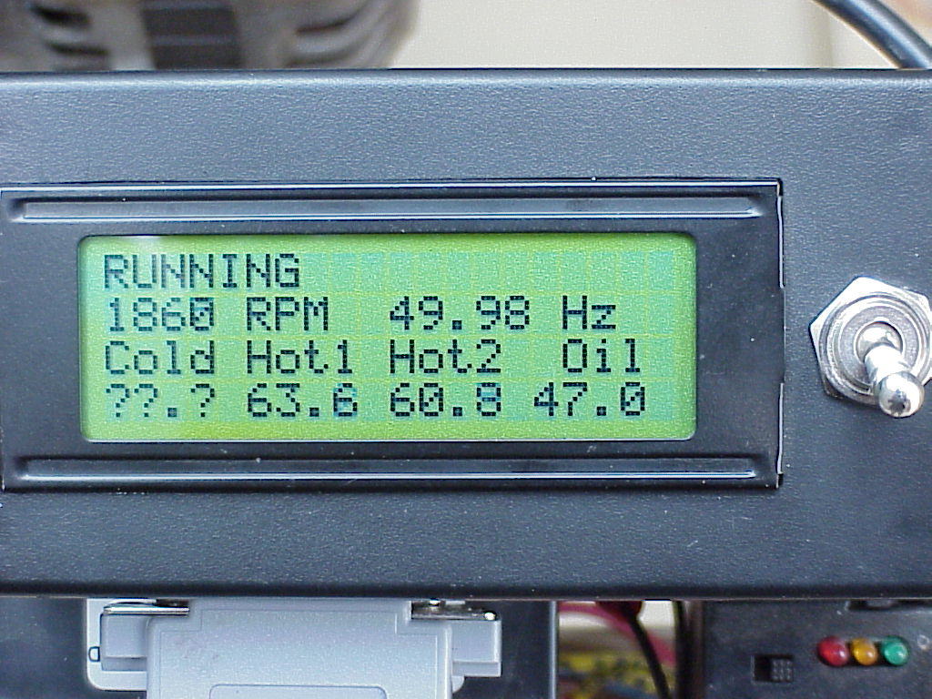
I use this techniqe to measure my generator output frequency (nominally 50Hz) to 2 decimal places - while being able to update the display several times a second. Same for the engine RPM - updating several times a second and displaying the nominal 1883 RPM - I only display to RPM, but could easily display to more precision if the need was there.
GWatPE Senior Member Joined: 01/09/2006 Location: AustraliaPosts: 2127
Posted: 08:11am 12 Mar 2010
Copy link to clipboard
Print this post
Hi Ross,
the maths is what makes most steer away from measuring an interval. Having increasing counts for increasing rpm is pretty logical. Having the counts decrease for increasing rpm puts a lot OFF going this way.
Gordon.
become more energy aware
Downwind Guru Joined: 09/09/2009 Location: AustraliaPosts: 2333
Posted: 08:29am 12 Mar 2010
Copy link to clipboard
Print this post
Hi Ross,
Very good point you bring up and i have used this method in other things but must admit it never crossed my mind for this application....Guilty of not thinking outside the square.
The original direction of this thread was to use a push bike meter to record the speed and i was not thinking outside of the standard method used.
It would seem William is now keen to have a play with a picaxe and do some data logging which would allow for your method to be used.
As Gordon said the math can get a little dawnting at the beginner level with programming so might tend to steer away from your method if able.
I do like you thinking though, and kick myself for not thinking of it with a earlier aneometer that i scrapped because of low reading abilitys.
I like being corrected with practical solution.
Pete.Sometimes it just works
RossW Guru Joined: 25/02/2006 Location: AustraliaPosts: 495
Posted: 09:42pm 12 Mar 2010
Copy link to clipboard
Print this post
The code need not be so scary. Here's a few snippets out of my genset controller (an Atmel, but the principles remain valid):
' divide hertzconf by freq to get hertz*100 (ie, 2 decimal places, based on 8MHz clock and /64 prescaler)
Const Hertzconv = 12500000
The ISR is basically just this:
Inthz = Timer1
If Inthz > Lastcount2 Then Freq = Inthz - Lastcount2
Lastcount2 = Inthz
And to get the frequency for display on the LCD:
L = Hertzconv / Freq / 100
Here's a display when I was making it. (The cold sensor was unplugged at this stage)
kingw Newbie Joined: 07/03/2010 Location: United StatesPosts: 23
Posted: 09:59pm 12 Mar 2010
Copy link to clipboard
Print this post
I have to comment that a lot of these recent developments do land outside of my understanding. I get a bit of it, but not enough to try and build it. On a positive note I did get 4 nice hard drives with great bearings in them. So this way I can build my bike computer one for giggles, and work with Pete on the photo interrupter (just pulled one of these out of a printer) one. With Easter coming up, the cups shouldn’t be a problem.
This will be fun to compare the read-outs between the two.
-w-kingw
RossW Guru Joined: 25/02/2006 Location: AustraliaPosts: 495
Posted: 01:58am 13 Mar 2010
Copy link to clipboard
Print this post
It's one of those things that seems very odd, until you "get" it - then it's pretty obvious.
For those who've never been exposed to this concept, I'll try to explain it in basic terms - with examples - hopefully someone will/can benefit from it.
We're all familiar with RPM, and since this post was about anemometers, lets start there.
1 RPM is 1 revolution per minute. OK, thats obvious.
60 RPM is 60 revolutions per minute. Similarly obvious.
Using a counter and a timer, you could count the number of pulses you get in a minute, and display it, but it takes a long time between updates and responds very poorly to changing conditions. You also have a maximum resolution of 1 RPM. That is, you can read 30 RPM, or 31 RPM, but not 30.5 RPM or better.
60 RPM is also (not quite as obviously) 1 revolution per second.
With updates once per second, you can see changes quickly, but you have lousy precision - 1 count per second = 60 RPM, 2 counts = 120 RPM, and nothing in between!
There is a way to get the "best of both worlds" - high precision AND high update rates - but it requires thinking differently.
Going back to the 60 RPM (1 RPS), imagine for a moment, if we could count to sixty in a second. When the reference mark on your shaft goes past, we start counting - and when it gets back to the same place, we stop counting. If we got to 60, it's obviously taken a whole second to turn 1 revolution (60 RPM).
Lets now say the shaft was turning twice as quickly - we start counting as the mark goes past, it gets back to the same place - but this time we've only managed to count to 30! We're counting the same speed, but it's got around in a count of 30, so it's going at 60 (how fast we can count in a second) divided by 30 (how many we counted to in one turn) = 60/30 = 2. So it's turning at 2 RPM.
If we'd only counted to 15, it would be turning at 60/15 = 4 RPM.
We can't count to 60 in a second, clearly - but a small computer chip certainly can. It can count way faster than that too.
Lets say it could count to 600 in a second. This will let us have a precision of 1/10 of an RPM while updating the display every second.
If we could count to 6000 in a second, we can now display to 1/100 of an RPM every second - or we could display less precision more often - like 1/10 of an RPM updated 10 times a second.
While we may not be able to read the display that fast, it could be very useful for example, in an MPPT system thats trying to adjust the output based on the wind speed - and it needs to do it quickly enough to stop things getting away in a gust.
In reality, many small processors give us access to counters that can reliably count millions of times a second. The small processor in my generator controller can count at 8 million counts per second - even counting the 50Hz output from the alternator (so the timing interval is 1 50th of a second) this 8 million is too fast. Fortunately, most of this type of chip also include a "prescaler" - which divides the frequency down to slower rates for real-world use. In the code I posted earlier, I divided the 8,000,000 counts per second clock by 64, to get 125,000 per second - still plenty of resolution when counting 50Hz.
Hope this helps someone,
RossWEdited by RossW 2010-03-14
Downwind Guru Joined: 09/09/2009 Location: AustraliaPosts: 2333
Posted: 03:27am 13 Mar 2010
Copy link to clipboard
Print this post
Well explained Ross.
One still needs a few sensors per rev or your timing interval becomes very long in low speed winds.
The count accuracy is still there.
I think 3-6 sensor readings per rev would be enough if interval timing was used.
It would also be very important to have each sensor exactly spaced or the interval count would vary.
Pete.
Sometimes it just works
GWatPE Senior Member Joined: 01/09/2006 Location: AustraliaPosts: 2127
Posted: 04:19am 13 Mar 2010
Copy link to clipboard
Print this post
I have used the pulsin command on a picaxe.
For my alternator, 1Hz=10RPM, so at a 4MHz clock, timeout is in around 0.6s, so you need at least 1 full AC transition per second.
The counts reading I divide 16, and then divide 65535 by this new count. This is then just treated as the unscaled RPM.
I can get RPM from 10-1000. The scaling factor in Gizmo's piclog program is 576, as I integrate 3 readings. This will work equally as well with a F&P, or an anemometer. RPM with an AxFx gives usually poor resolution with the picaxe count command, even with a 1 second interval.
As Pete has mentioned, the sampled pulse stream has to have good uniformity, as this will affect the measurement precision.
Gordon.
become more energy aware
Downwind Guru Joined: 09/09/2009 Location: AustraliaPosts: 2333
Posted: 10:52am 13 Mar 2010
Copy link to clipboard
Print this post
As there was a HDD motor on the bench from testing the HDD generator someone else asked about, i had a play at reading a pulse from the 3 phase motor.
With the use of a opamp i get a 4 pulse per rev square wave out.
There is a little drag caused by the magnet in the motor but this is marginal and think the HDD motor could be used as a pulse generator for an aneometer without modification.
This makes the project rather easy with limited construction and circuitry.


 .
.
 . The secret was to have the anemometer hanging down and the windvane on top.