Notice. New forum software under development. It's going to miss a few functions and look a bit ugly for a while, but I'm working on it full time now as the old forum was too unstable. Couple days, all good. If you notice any issues, please contact me.
Tinker Guru Joined: 07/11/2007 Location: AustraliaPosts: 1904
Posted: 08:25am 02 Jul 2018
Copy link to clipboard
Print this post
Thanks guys, for the kind comments.
Wow, what an interesting selection of alternative ways for lithium battery cell balancing has suddenly surfaced here. I had no idea about those methods...
But, printed words do not much to convey an idea to my ageing grey matter and warpspeeds sketch goes a long way to overcome this.
I would be happy to try something new if there was more info by way of schematics, having no idea how to create the drive signals etc. etc.
I do like the idea of the single turn transformer mentioned by warpspeed, could that be a small ring toroid?
To be useful for myself, this balancer should cope with at least 16 individual cells in the 100-200Ah range. I have 8 off 6 year old 200Ah cells and 8 off 3 year old 200Ah cells here, connected for a nominal 48V bank. This means my battery voltage fluctuates from ~54V floating voltage, fully charged and ~52V with very little charge as happened today with all rain and grey skies. Klaus
yahoo2 Guru Joined: 05/04/2011 Location: AustraliaPosts: 1166
Posted: 08:41am 02 Jul 2018
Copy link to clipboard
Print this post
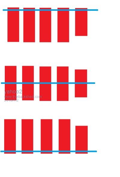
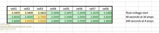
I agree. I worried about balancing a lot, so I run a experiment on a 3.5 year old 400ah 24 volt bank.
after 589 days with no balancing. I done an eight minute balance with bypass resistors that max out at 2 amp but usually bypass around a third of that.
I ended up draining 0.6 watts from cell 3 to fully balance the bank
notice that there are 5 cells with higher voltage than cell 3 at float yet they are all lower than cell 3 when the cells are charging and full.
I think constant balancing is flawed logic. I'm confused, no wait... maybe I'm not...
Warpspeed Guru Joined: 09/08/2007 Location: AustraliaPosts: 4406
Posted: 09:56am 02 Jul 2018
Copy link to clipboard
Print this post
Klaus,
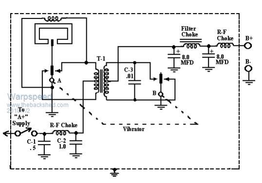
Back in ancient times before semiconductor devices, everything used valves which needed to be run from a high voltage dc power supply. For things like a car radio that only had the 12v car battery, a thing called a vibrator power supply was used. You might even remember those from your youth.
These had vibrating contacts in both the primary and secondary side of the transformer that worked together synchronously. The contacts in the primary generated an alternating square wave, and the contacts in the secondary converted a higher voltage square wave back into dc. Mechanical rectification if you like. There were no silicon diodes in the very early days.
Now the curious thing about this is that if you could keep the vibrator going, the whole thing is completely bi directional. This is what Wiseguy referred to earlier as "a dc to dc transformer".
If we replace the vibrating contacts with mosfets, we can achieve the same effect of having an isolated dc to dc power supply that is completely bi directional. One side chops up the dc into an ac square wave, and the other side acts as a synchronous rectifier turning the ac back into dc.
If the transformer is 1:1 ratio and we have two battery cells, one on either side, they effectively become solidly linked in parallel, but without any direct galvanic connection. Power will flow from the higher voltage side to the lower voltage side until the voltages become exactly the same. And the effect is completely bi directional. Cheers, ĀTony.
Tinker Guru Joined: 07/11/2007 Location: AustraliaPosts: 1904
Posted: 10:37am 02 Jul 2018
Copy link to clipboard
Print this post
Well, maybe for some cells.
On my 6 year old ones from which I had disconnected the balancing while re arranging wiring, one cell shot up to over 4 volts in the absorbing stage. This happened over a few days. I got it back to normal with my shunt balancer eventually.
I shall keep the balancing going from now on, these cells are too expensive (to me) to ruin by neglect. It takes very little power to run my balancing gizmo.Klaus
Tinker Guru Joined: 07/11/2007 Location: AustraliaPosts: 1904
Posted: 10:49am 02 Jul 2018
Copy link to clipboard
Print this post
So you could link 16 cells via 16 1:1 windings and they *all* assume the same voltage? Sounds like black magic to me but I believe you.
Is that 'same voltage' the average of all cells?
And how much or little by way of Amps is there being shuffled around? I suppose that depends on the cell voltage difference and the 'shuffled' current drops to zero once all cells get to equal potential?
I suppose this method would work a lot quicker than my present 'relay shuffling' where each cell gets connected only once every 56 seconds to get a measured boost, depending how much, or little, it needs.Klaus
yahoo2 Guru Joined: 05/04/2011 Location: AustraliaPosts: 1166
Posted: 12:41pm 02 Jul 2018
Copy link to clipboard
Print this post
Hi Klaus, when I mentioned constant balancing, I am talking about balancing at any voltage. I only balance at 3.6 volts on a CALB bank because that is where they need to be all level. if I balanced at 3 volts they will not be level at 3.6 volts, the smallest capacity cell will hit full and shoot up in voltage before the others.
you guys are balancing voltage and assuming that equates to balancing capacity
if you try and make the voltages level over a range of state of charges the smallest cell will be constantly adjusted every cycle. I'm confused, no wait... maybe I'm not...
Tinker Guru Joined: 07/11/2007 Location: AustraliaPosts: 1904
Posted: 01:45pm 02 Jul 2018
Copy link to clipboard
Print this post
Hmmm, I admit I did not fully understand just exactly what you meant by "constant balancing". Thanks for explaining.
However, "balancing at 3 Volts" makes no sense at all as the cells are just about empty then and most likely - mine would - show equal voltage at each cell.
From what I understand, battery cell capacity and its voltage level are related. 3.6v would indicate to me the cell is full. That is the voltage anyway where my outback charge controller does the absorption stage and the charge current drops right back.
To my way of seeing it one cannot balance cell voltages by itself as this also affects the cell charge level. But I'm happy to stand corrected if I missed something here.
BTW, what is a "CALB" bank? Klaus
Warpspeed Guru Joined: 09/08/2007 Location: AustraliaPosts: 4406
Posted: 10:38pm 02 Jul 2018
Copy link to clipboard
Print this post
They will "try" to all assume the same voltage, but if the cell capacities are greatly different that can never really happen throughout the full charge/discharge cycle. It might just settle down to having some average mean cell voltages that are still different to each other, but not by as much.
The current flow is going to be determined by the internal resistance of the switching circuit. Mosfet rdson and transformer winding resistances for example may be made fairly low, but can never be zero.
The whole balancing issue is rather contentious, everyone has different ideas, and our applications do vary.
Solar people usually top balance because the idea is to keep the cells as fully charged as possible without having one cell go super high voltage and be damaged. We terminate charging when any one cell reaches the max voltage, so we want all to reach max voltage together if at all possible. This is why I like the individual cell discharger that sucks some power when above a precisely set voltage threshold.
The electric vehicle guys generally balance down to end of charge voltage, because they want as much mileage range as possible without the weakest cell being damaged. The applications are very different and different strategies are needed.
This bi directional power shuffling idea could be used on only two cells for example. If you linked just your strongest cell to your weakest cell, it might be of some help squeezing some more useful life out of the weakest cell.
I cannot think of a way to come up with a useful specification to design a thing like this, because everyones idea of what is required will be rather different. Cheers, ĀTony.
Warpspeed Guru Joined: 09/08/2007 Location: AustraliaPosts: 4406
Posted: 11:00pm 02 Jul 2018
Copy link to clipboard
Print this post
That is how I see it too.
The weakest cell will have the greatest voltage swing, highest voltage when charging, lowest voltage when discharging. I believe it is important to be able to record on a visual display display the peak maximum and minimum voltages reached of each cell, as well as the current real time voltages.
If all the maximums and minimums and the current voltages all line up across the screen, well and good. If something is slowly deteriorating with one particular cell its then very easy to see the peaks have spread further apart, and corrective action can then be taken.
A large clear visual display can be taken in at a glance. Columns of numbers from a data logger require far more effort to interpret, especially where there are a great many cells to monitor.
Cheers, ĀTony.
wiseguy Guru Joined: 21/06/2018 Location: AustraliaPosts: 1000
Posted: 02:25am 03 Jul 2018
Copy link to clipboard
Print this post
There is a lot of correct things being said, perhaps some less correct, lets re focus on what is written about LiIon Cells and their proper care and maintenance - I welcome information that is more correct - the purpose of this is to inform others prompt discussion and learn more ourselves in the process. If I refer to battery it is more than 1 cell. NB I am also posting about only 1 type of LiIo chemistry (LiPo).
1)LiIo cells usually operate from 3.0V to 4.2V Empty to full charge note1: Opinions vary down to 2.8V and up to 4.3V note2: always follow manufacturer's advice closely for the cells they supply 2)Taking LiIons above or below these levels may cause irreversible damage 3)Capacities & performance are never/rarely exactly the same between cells 4)Loss of a cell's capacity or self discharge often arise over their life & use 5)Series charging of batteries does not guarantee equal cell voltage distribution 6)Like wise Series discharge of batteries to an end point. 7)A mistake of overcharge on 1 cell can be catastrophic if it goes feral in a string 8)Mismatch of cells performance and capacity usually deteriorates over time 9)Charge rate should generally be held between .5C and 1C 10)Cells are damn expensive
Now some other discussion. As I understand it the most critical issues with LiIon cells occur at end of capacity ~3V and at Max capacity ~ 4.2V. For the main 95% of capacity between these points life is good.
My view is that not balancing batteries is flawed logic (poking a hornets nest lol)
The cells are essentially a chemical reaction and the 100% capacity point is mainly dictated by the 4.2V and reduction of charge current at some end point (0.05C?)
Whilst balancing is not really required for 95% of the time it is really needed at end of capacity and at the other extreme when approaching full charge.
With an active balancer such as my earlier post it should be possible to connect a 100AH cell and 2 x 10AH Cells in series and draw ~11V @ 2A for 60 hours - this is not a proposal or suggestion (dont try this at home) but it should work.
If an active balancer is used 100% of the time, it will mask a poorly behaving Cell so a method or mechanism of identifying such a cell is probably still required - this is a work in progress.....
I am working on posting a suggested circuit for an active balancer but this is still a few days off - finding stuff that operates well on 3V is a bit of a pain whilst also trying to keep it uncomplicated.
Edited by wiseguy 2018-07-04If at first you dont succeed, I suggest you avoid sky diving.... Cheers Mike
Warpspeed Guru Joined: 09/08/2007 Location: AustraliaPosts: 4406
Posted: 02:43am 03 Jul 2018
Copy link to clipboard
Print this post
The actual recommended cell voltage range can vary quite a lot between different manufacturers that use slightly different cell chemistries.
Its a bit of a "magic pudding" where secret ingredients can give some perceived advantages over competitors cells.
But basically there will be a very flat voltage characteristic, and at either end a point where the voltage change becomes increasingly steep.
My own thoughts are, that if you stay in the flat portion you may be giving up some total capacity, but the whole thing becomes a lot easier to manage and is probably a lot more gentle on the cells long term.
If the cells are new and in first class condition and not thrashed, according to a great many people they stay pretty much in balance all by themselves without needing any help.Cheers, ĀTony.
wiseguy Guru Joined: 21/06/2018 Location: AustraliaPosts: 1000
Posted: 04:17am 03 Jul 2018
Copy link to clipboard
Print this post
I concur with most of your comments. But if I understand you, instead of say 3.0V & 4.2V you are more conservative and keep the range between 3.1V and 4.1V?
My gut feel is that the chemical reaction is partially incomplete (so less than 100% capacity) and there is still no guarantee of equal voltage distribution to stop a single cell exceeding its max limits (or min limits discharging)?
I have a confession... I dont even have a string of batteries exceeding 10AH ATM. (and I'm STILL waiting impatiently for my EGS0002 boards to arrive)
We are just about to build a new house and I want lots of solar & lots of storage & a decent inverter, hence finding this forum in the process.
I personally will use an active balancer but the finer details are still a work in progress to be determined. Maybe it will only operate when below 10% and above 90% state of charge.
Edited by wiseguy 2018-07-04If at first you dont succeed, I suggest you avoid sky diving.... Cheers Mike
Warpspeed Guru Joined: 09/08/2007 Location: AustraliaPosts: 4406
Posted: 05:33am 03 Jul 2018
Copy link to clipboard
Print this post
I have a 5Kwh of Winston cells, here but they are not yet in use. I did some trial charges and discharges a while back, nothing too drastic. But the voltage begins to rise at an ever increasing rate above about 3.4v. Charging stops when any cell reaches 3.45v and over voltage disconnect is set to trip at 3.5v.
Its very conservative, but then I am just starting out.Cheers, ĀTony.
yahoo2 Guru Joined: 05/04/2011 Location: AustraliaPosts: 1166
Posted: 05:42am 03 Jul 2018
Copy link to clipboard
Print this post
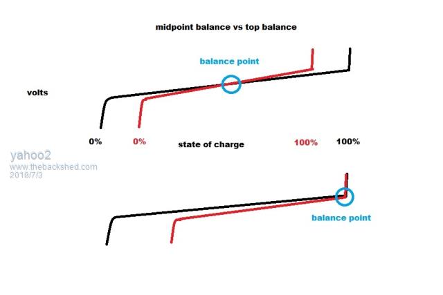
I have obviously done a crappy job of explaining this, maybe I can do it with pictures.
the red line is a cell with less capacity than the black line (rest of the cells). If I balance at a specific state of charge all the cells will be at that voltage EVERY CYCLE and the smallest cell will always hit full or empty before the others.
We need to chose a voltage to balance very close to the top and stick to that voltage so that all the cells hit the "knee" together. Then we trigger our low voltage disconnect before the smallest cell gets to the bottom "knee".
with really old cells I would prefer to balance at the bottom and stay away from full charge but solar being what it is there are almost no opportunities to bottom balance a battery bank.
CALB is cells made by china aviation mainly for submarines, they have slightly different voltages than winstons.
we assume we are talking about lithium iron phosphate, they tend to be large format and not such a fire hazard, they tend to be full between 3.6 and 3.8 volts depending on the brand and how fast they are charged.
The way I do it is have an upper limit of 3.4875 volts per cell then I balance between 3.6-3.65 volts about six times a year or less. seems to work OK, haven't had a client with a problem yet. (touch wood)Edited by yahoo2 2018-07-04 I'm confused, no wait... maybe I'm not...
wiseguy Guru Joined: 21/06/2018 Location: AustraliaPosts: 1000
Posted: 06:13am 03 Jul 2018
Copy link to clipboard
Print this post
Thanks Yahoo2 - I think I get you now - a picture is worth a heap of words, but it raises another couple of questions for me.
How do you know the weak cell is at its midpoint of capacity - is cell voltage a relatively reliable indicator of remaining capacity ?
Your method sounds a little like a type of equalisation where you try to set the string capacity midpoint to match the weak battery capacity midpoint. But it appears this also reduces the capacity range for the whole bank ?
My understanding is that an active balancer would give one the best results at all points along the good batterys capacity curve.
All the "better" batterys will assist the weaker battery as far as delivering capacity to load (they would all contribute to the capacity loss of the weaker battery by slowing its progress to low end point) - all cells ideally reach the exhaustion point at ~ the same time. When charging the weaker battery (without balancer running the weak cell would peak out earlier), but the balancer now works in reverse and shares any minute over charge on the weak battery between all the other cells until the ideal total string voltage is reached.
I dont see it as driving the poor little weak battery harder whilst cycling but rather helping it & slowing its demise whilst minimising capacity loss for the whole string. Edited by wiseguy 2018-07-04If at first you dont succeed, I suggest you avoid sky diving.... Cheers Mike
Tinker Guru Joined: 07/11/2007 Location: AustraliaPosts: 1904
Posted: 09:50am 03 Jul 2018
Copy link to clipboard
Print this post
I do hope you ordered more than one board . I have half a dozen busted EG002 boards here. They do work but also expire easily.
If yours is for an inverter do read the modifications we did to them, posted way back in the beginnings of my inverter builds.
EG002 problems have steered the inverter builders here to make their own version control board with the EG1810 chip doing the tricky bits.Klaus
wiseguy Guru Joined: 21/06/2018 Location: AustraliaPosts: 1000
Posted: 03:57am 04 Jul 2018
Copy link to clipboard
Print this post
Thanks Klaus, Yes but I have only ordered 2 EGS002 for now - I intend to treat them nicely - well to start with anyway. I also ordered some EG8010 to DIP boards for some more serious future work. I will modify the EGS002 boards as you advised.If at first you dont succeed, I suggest you avoid sky diving.... Cheers Mike
Warpspeed Guru Joined: 09/08/2007 Location: AustraliaPosts: 4406
Posted: 05:28pm 04 Jul 2018
Copy link to clipboard
Print this post
The main reason the EGS002 boards die is that the isolated mosfet gate drivers are located on the EGS002 board. When a mosfet finally goes to mosfet heaven, it more often than not kills one of the the driver chips on the EGS002.
If you fit a proper heavy grunt non inverting gate driver on the power board, either one of Mad's Totem Pole wonders, or some serious gate driver ICs (in sockets!) then that protects the wimpy gate drivers on the EGS board which are not really up to the job of driving multiple monster fets anyway.
Like everyone else I have blown up a few EGS boards, they are certainly cheap enough, so best to get a few of them just in case.Edited by Warpspeed 2018-07-06Cheers, ĀTony.
yahoo2 Guru Joined: 05/04/2011 Location: AustraliaPosts: 1166
Posted: 12:35am 05 Jul 2018
Copy link to clipboard
Print this post
No , you have it backwards, I am saying DONT balance anywhere away from one end or the other. choose one point and stick to it.
Perhaps there are some things you wont understand until you run a battery bank hard and your active balancer will not keep up and you cook your first cell, or worse, cook someone elses.
Lithium cells dont always give you nice slow absorption cycles, I have seen banks charge for forty minutes and the taper at the end is 12-30 seconds if you are off by even 2-3 watts at the end and you are measuring total bank voltage to control the charge rate, it will not see one high cell you are going to have to dissipate 100-200 amps. The individual cell high voltage disconnect is supposed to be a failsafe not a regular event.
Yes I know that new perfectly matched cells can run for years with nothing keeping an eye on them but this is a DIY site where cheap old mismatched gear is catered for. I'm confused, no wait... maybe I'm not...
Warpspeed Guru Joined: 09/08/2007 Location: AustraliaPosts: 4406
Posted: 01:34am 05 Jul 2018
Copy link to clipboard
Print this post
Its really scary how fast the voltage on one particular cell can rocket upwards at the end of charging. Its vitally important to monitor all the cell voltages individually and stop charging as soon as any individual cell "takes off", and that can happen in seconds even at quite low rates of charging.
Once you have personally seen this effect with your own eyes, you will be astonished. Its the reason why many people prefer the individual cell discharge loads that cut in and out at a very specific voltage.
The cell that takes off first will start its discharger going first, and charging will then abruptly cease as the cell voltage rockets up to the charger turn off. The cell discharger continues to pull more power for a brief period from that same cell, until that high cell falls back and the discharger cuts out.
In this way, the cell that takes off first, and has the highest voltage at the end of the charging cycle, has a small amount of current "stolen" by the discharge load each charge cycle, and that allows all the others to gradually catch up over time.
As this happens at the end of every charge cycle, eventually all the cells will start to "take off" pretty much simultaneously, and the cells will then be quite closely top balanced.
Its fascinating to watch all the individual cell voltages very slowly march up the screen pretty much in a straight line. Then at about 3.40v several will break into a sprint up towards the 3.45v finish line, where the charger cuts off. This all happens within a minute or two.
I see no point in charging to a much higher voltage as some people do. The difference between reaching 3.45v and 3.55v is about twenty seconds of charging time. That is not going to help the actual state of charge very much.
I would stop at 3.40v, except that last 50mV is where the cell balancing load switches in, and its what makes the top balancing work very selectively.Cheers, ĀTony.


 but I believe you.