
|
|
Forum Index : Microcontroller and PC projects : CMM2 Expansion Module Design Contest
| Page 1 of 2 |
|||||
| Author | Message | ||||
| RetroJoe Senior Member Joined: 06/08/2020 Location: CanadaPosts: 290 |
I was mostly joking in this thread, but perhaps the CMM2 community should have a serious chat about designing and fabricating a "standard expansion module", that is compatible with the form factor of the CMM2 reference PCB design. An edge connector approach does not feel like the right solution. These are ideal if you want to expose the entire CPU bus and will be using most/all the signals at once on a peripheral (e.g. RAM/ROM expansion). It also enabled the classic 8-bit era cost-cutting "trick" (Sinclair, Commodore, et al) of putting a male edge connector on the motherboard, forcing the peripheral manufacturers to bear the cost of the expensive female edge connector. GPIO signals are more selective, and what seems to happen is: * some GPIO pins being more in "demand" than others * running out of the current allowance on the +5V and 3.3V rails * consuming GPIO pins for peripherals that logically would go on the CMM2 PCB (e.g. PS/2 mouse jack, ESP01 module for WiFi, etc) It crossed my mind when I was wiring up my PS/2 mouse interface that this is not something "nostalgia seekers" would necessarily want to do, nor necessarily have the skills for, but a low-cost "EZ-PCB" would be appreciated. I know a few folks are manufacturing "souped up" CMM2s with some/all of these features, but a cheap, mostly passive, prefab PCB for expansion would be ideal for the existing CMM2 installed base. The design spec as I would like to see it is roughly: * external USB power and rectifiers, at minimum with fixed +5V and +3.3V volts and maybe one adjustable one * PCB traces that allow the simple soldering of parallel headers (4 to 6). This would allow the flexibility to add full or partial headers, male or female * a prototyping area that included a "sea of holes" + standard "6 + 6" DIP configuration, and easy access to the power rails * prewired pads for PS/2 mouse and ESP01 connections * designed to accommodate a PS/2 jack, and to clear the standard CMM2 case and sit on top of it (something like Tom's photograph). Thoughts? Edited 2021-02-01 05:20 by RetroJoe Enjoy Every Sandwich / Joe P. |
||||
| elk1984 Senior Member Joined: 11/07/2020 Location: United KingdomPosts: 232 |
It's an attractive idea to have CMM "HAT"s count me in! |
||||
| RetroJoe Senior Member Joined: 06/08/2020 Location: CanadaPosts: 290 |
I agree :) From what I've read, the CMM2 GPIO pins are in fact compatible with the "HAT" ecosystem, but I've never attempted that. One more requirement: "global availability" to promote adoption of "core" HW capabilities. This could be achieved by having Geoff and/or Peter sign off on the reference design, and all the folks currently engaged in low-volume PCB manufacturing (I'm not one of them !) could make it locally available. P.S. Here's a very rough approximation of what I have in mind, but with a right-angle female header, not a male edge connector. The Apple II hardware hobbyist market is probably much bigger than the Maximite one... but I'm not certain about that. 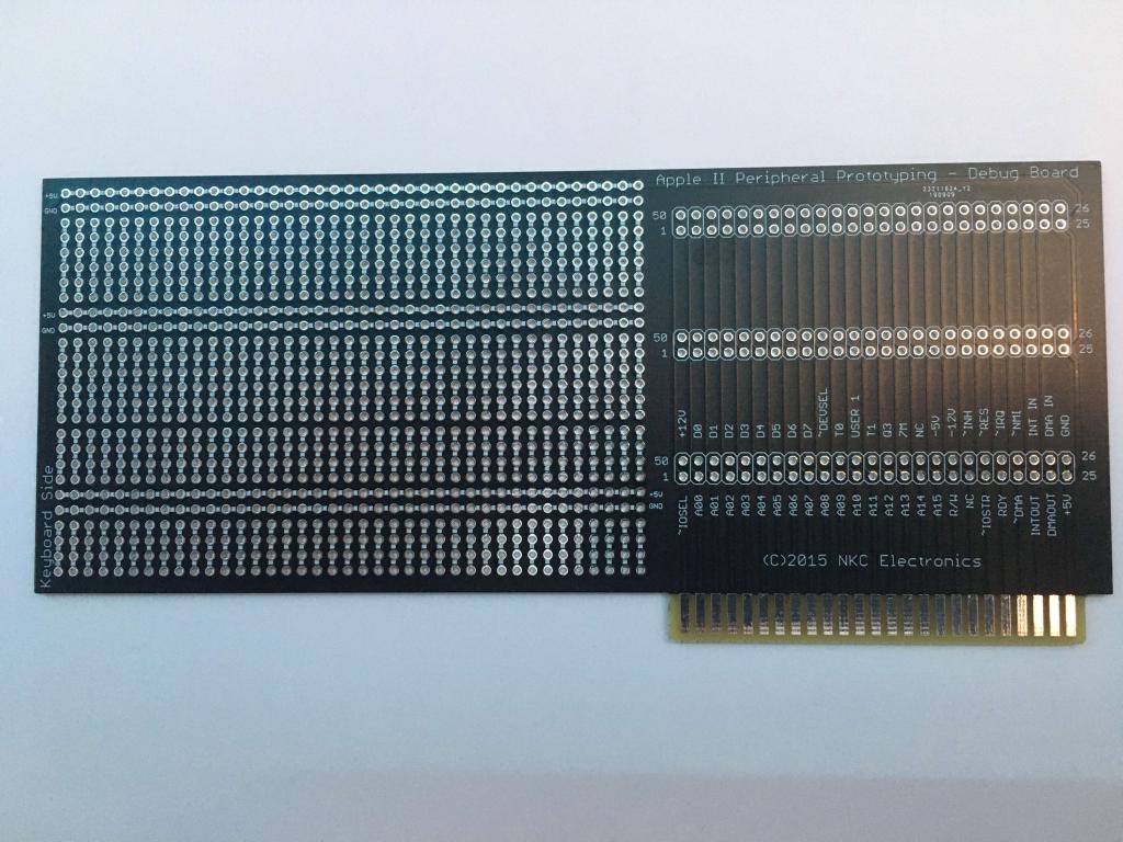 Edited 2021-02-01 04:54 by RetroJoe Enjoy Every Sandwich / Joe P. |
||||
mclout999 Guru Joined: 05/07/2020 Location: United StatesPosts: 509 |
I think it should fit inside one of the same standard enclosure used for the CMM2 so it can be stacked on top. Then a simple short 40 pin cable can link them and you can cut holes in the front and back of the faceplate of any ports you need for the addons. They call me Shai-Hulud (The maker) |
||||
| elk1984 Senior Member Joined: 11/07/2020 Location: United KingdomPosts: 232 |
A few random thoughts about design. For example, the "mouse" could have been something an end user could build with a "template" expansion housing that could take a chip holder, some dupont connectors to plug the chip to the connector to the CMM2 etc. This is something that could easily be extended to other use cases / chips etc. 1. Abilty to use off the shelf components in a solderless solution. Something that presented a breadboard ready for use with dupont connectors and components would be great. 2. Should interface using standards built into the CMM2 whereever possible (Serial, I2C etc.) removing the need for drivers etc. 3. Keeping components safe in daily usage - this leans towards an enclosed design. 4. Ease of plugging / unplugging to the CMM2 - robustness of cables - perhaps something that takes the ribbon into a round cable? Minimal length cables would be best to keep desks tidy. 5. The range of CMM2s that exist. It would be great to have a solution which plugged into the back of a CMM2 which daisy chained ports to the rear of the expansion unit, but there are practical considerations (cost, complexity, possible power drop off) as well as a range of implementations meaning no standardized physical form factor. 6. Something compact? Most of the components being looked at power extend the rear of the CMM2 by no more than 3-4cm. A unit which doubles the depth of the unit would be cumbersome. 7. Potential to stack expansions on top of the CMM2 (at which point something the size of a standard unit would probably be better. I'm sure this is a wildly ambitious wish list. But here's my two-penneth. Edited 2021-02-01 05:59 by elk1984 |
||||
| Mixtel90 Guru Joined: 05/10/2019 Location: United KingdomPosts: 8913 |
I was thinking of this expansion only last night... :) It's a gaming box for 2 players, with an individual joystick and scoreboard for each. I envisaged an identical case with two 4-digit multiplexed LED displays (one for each player) and 2 standard switch-type joysticks (on the sides). They are connected to a 28-pin Micromite as the "brains" and linked to the CMM2 over I2C. Connection would be via a 6-way female Dupont connector plugged into pins 1-6 of the I/O connector. 1 - omitted 2 - 5v 3 - SDA 4 - 5v 5 - SCK 6 - GND An internal LDO regulator would power the board at 3.3v. I didn't work out whether putting the Dupont in upside down would cause damage. lol Using just I2C leaves all the rest of the I/O port free, of course. This is just an example, but a similar approach bringing the pins of the external Micromite to pins/pads on a PCB might be an idea. The length of I2C connection to a stacked board probably isn't too bad. This is as far as the idea got, apart from a quick sketch to see if there would be enough pins on the Micromite (I think there are, even reserving console pins). Mick Zilog Inside! nascom.info for Nascom & Gemini Preliminary MMBasic docs & my PCB designs |
||||
| elk1984 Senior Member Joined: 11/07/2020 Location: United KingdomPosts: 232 |
Or have standard sized cut outs on the front / side (depending on where the extender is designed to be mounted) that can be pushed out to fit (for example) a USB port, DB-9 port, Nunchuk connector or even the full GPIO? |
||||
TassyJim Guru Joined: 07/08/2011 Location: AustraliaPosts: 6541 |
I have a supply of old IDE cables and the connectors are cheap so: 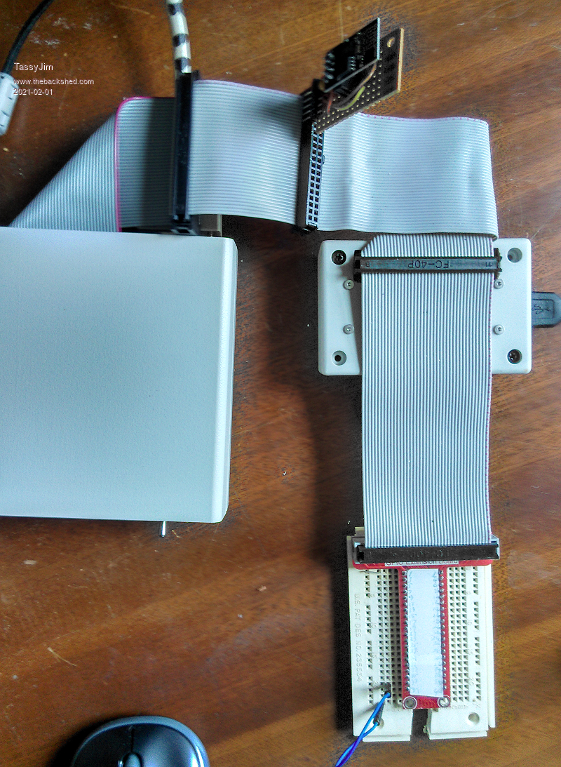 There is a short IDE extension cable attached to the CMM2 to save the main connector from rough handling. On the first socket is the ESP8266 then comes the mouse. It's permanent so gets a box! I might add the ESP to the mouse house. Finally the breadboard. I can add as many IDE connectors as required and I can always find a longer cable if needed. Just need a bigger desk. One thing I have learnt is to only use as many pins on the strip-board as you need to connect to the IDE. Plugging in all 40 pins gets to be very tight and an unnecessary strain. You also have to be careful using pin 40 and now pin 37. They are checked on boot-up so any load to ground should be avoided. Jim VK7JH MMedit |
||||
| RetroJoe Senior Member Joined: 06/08/2020 Location: CanadaPosts: 290 |
A $2 IDE cable - very nice! A professor once told us, "A good engineer is someone who can build for a quarter what any idiot could build for a dollar" :) I suppose my mind was oriented towards a more finished/permanent/robust solution, given how fragile my little PS/2 "barnacle" looks hanging off the back of my CMM2. But, I'm going to go cannibalize my decommissioned Pentium boxes Right Now. Nice thing is I can now tell my wife: "See, there *was* a reason I've kept them all these years!" Edited 2021-02-01 06:52 by RetroJoe Enjoy Every Sandwich / Joe P. |
||||
| elk1984 Senior Member Joined: 11/07/2020 Location: United KingdomPosts: 232 |
This could work. Except the enclosed part because at least once every six months I send a tidal wave of tea across my desk  |
||||
| elk1984 Senior Member Joined: 11/07/2020 Location: United KingdomPosts: 232 |
I have an FPGA inside an old desktop beige case. If I could squeeze a CMM2 in that, my desk would be tidier and the satisfaction of "I did it because it was there" would be complete! |
||||
| TassyJim Guru Joined: 07/08/2011 Location: AustraliaPosts: 6541 |
If you do use IDE cables, make sure it isn't an 80 core one. They are not a good choice even if the connectors do have the correct number if pins. They have all sorts of internal bridging that will not play nicely with the CMM2. Also, some IDE cable have one pin blanked out as a means of orienting them correctly. There are still plenty that have all 40 pins/cores available. Having the correct tool for adding connectors helps but I have been know to use multigrips or a vice instead. Jim Edited 2021-02-01 07:28 by TassyJim VK7JH MMedit |
||||
| Nimue Guru Joined: 06/08/2020 Location: United KingdomPosts: 427 |
My CMM2 looks like this -- ribbon cable to breadboard glued to the top of the CMM2 case -- keeps it tidy for simple prototyping.. 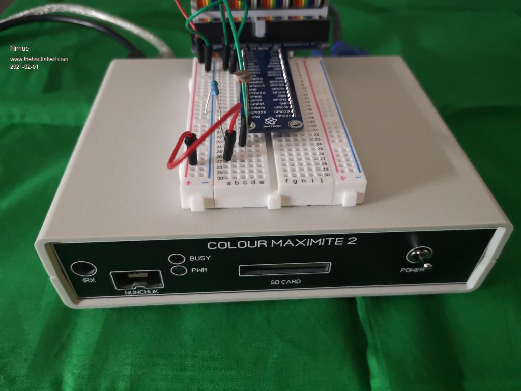 Entropy is not what it used to be |
||||
| frnno967 Senior Member Joined: 02/10/2020 Location: United StatesPosts: 105 |
In another thread, Piotr Siwy (PS Labs) mentioned that he was going to work on an expansion box for the stock CMM2. It would be great to have something like that as an option instead of having to roll our own hardware. I bet he could help get a design bootstrapped really quickly. Jay Crutti: Ham Radio Operator, K5JCJ. Computer Enthusiast. Musician. Engineer. |
||||
| siwypiotr Senior Member Joined: 18/08/2020 Location: PolandPosts: 127 |
Dear Maximite fans! In fact Im working on expansion system now. In 1 week I should have first prototype delivered. This will consist of expansion board that will use bottom half of maximite enclosure (it will nicely stack on maximite): 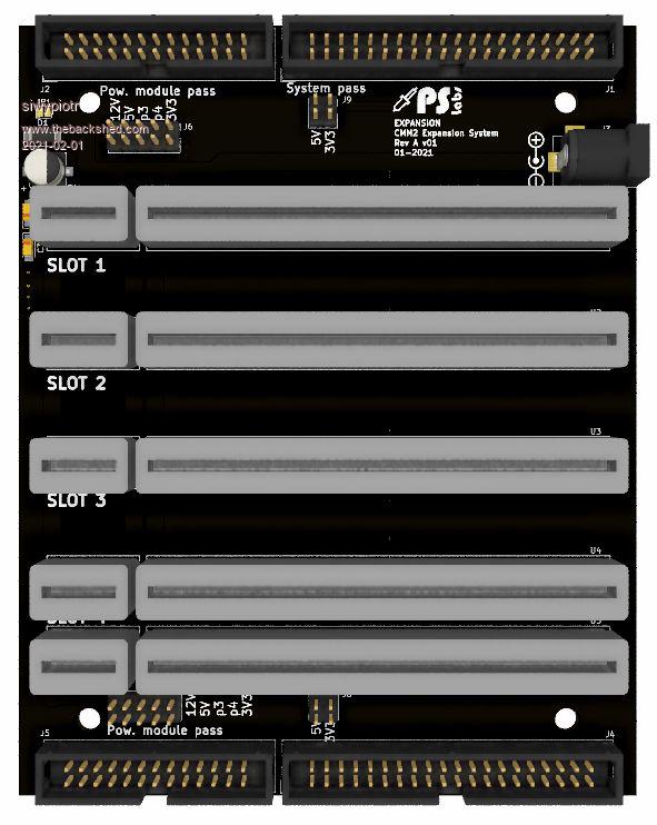 Expansion can be daisy chained toogether. It will be connected with ribbon cable with maximite. As You can notice there is additional ribbon cable. This one will carry multiple voltages and most importanly additional signals so daisy chained expansions can communicate with each other. Module will be powered using 12 V, 12 volts rail will be available on expansion card bus, mainly it will be used for power module. Each expansion card will have the jumper so You can choose which power supply You want to use, from maximite or from power card. With the first prototype order I will receive following modules: Prototyping card 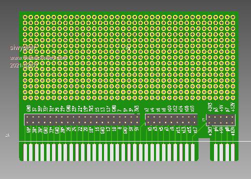 Power module This will deliver 5v and 3v3 volts from highly efficient step down converters. This will be efficient enough to run for example relay array 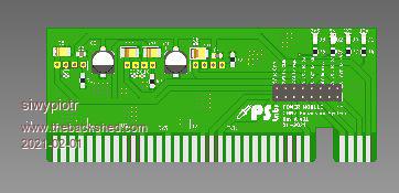 Mouse, joystick and additional Nunchuk This will use HT chip for mouse 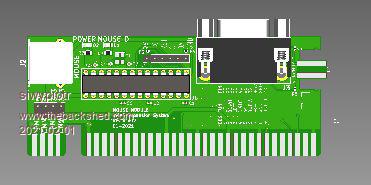 WiFi with ESP module This will also i nclude USB to UART chip so You can easily flash the ESP 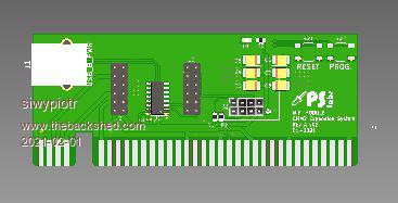 Led array using shift registers This is mainly to experiment with shift registers this will give a ground for card like relay arrays, they will communicate using additional ribbon cable on expansion board. 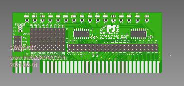 Soon I will give to public github project. This will include everything You need to design Your own expansions. My target is to have this available in my shop in 4-5 weeks: https://sklep.pslabs.pl/Maximite-c91 Edited 2021-02-01 19:53 by siwypiotr |
||||
| thwill Guru Joined: 16/09/2019 Location: United KingdomPosts: 4369 |
Looks like @siwypiotr is aiming for a "gold standard" but for those with more modest interfacing ambitions can I give a shout out for the CMM2 prototyping boards produced by @bigmik: https://www.thebackshed.com/forum/ViewTopic.php?TID=6992&PID=149992 Best wishes, Tom MMBasic for Linux, Game*Mite, CMM2 Welcome Tape, Creaky old text adventures |
||||
bigmik Guru Joined: 20/06/2011 Location: AustraliaPosts: 2981 |
Thanks Tom.. Regards, MICK Mick's uMite Stuff can be found >>> HERE (Kindly hosted by Dontronics) <<< |
||||
| siwypiotr Senior Member Joined: 18/08/2020 Location: PolandPosts: 127 |
Schematic for expansions system: exp_syst_REVA_v02.pdf pins x1 to x20 wil carry additional signals for expansion modules communication, signals x1 to x18 are also available for next expansion system You connect. p3, p4, p7, p8 - are free power lines that can be used in future On jumpers J8 and J9 You can decide of the 3v3 anf 5v rail from maximite should be chained. J6 and J7 you decide if voltage rails from power module should be chained. Edited 2021-02-01 20:10 by siwypiotr |
||||
| romba6 Newbie Joined: 04/07/2020 Location: United KingdomPosts: 37 |
Excellent work Piotr, this looks a very practical and expandable solution. Look forward to seeing it in your 'shop'. I'm currently using bread board expansion so for me prototyping card(s) will be a big plus. |
||||
| mclout999 Guru Joined: 05/07/2020 Location: United StatesPosts: 509 |
siwypiotr Hi. is this the expansion system that the relay controller board I WON will work with and when will that be coming my way WINK WINK. They call me Shai-Hulud (The maker) |
||||
| Page 1 of 2 |
|||||
| The Back Shed's forum code is written, and hosted, in Australia. | © JAQ Software 2026 |
