
|
|
Forum Index : Microcontroller and PC projects : Shall I call this one Gemini?
| Page 1 of 4 |
|||||
| Author | Message | ||||
| Mixtel90 Guru Joined: 05/10/2019 Location: United KingdomPosts: 8913 |
Twin PicoMites Another odd idea that came from some doodling.... PICO1 is a VGA device, with the usual display (simplified) and keyboard. I/O wired out. GP10-GP13 are wired to a 4-way female header, with pullups on GP10 and GP11. It gets it's supply from a linear regulator. PICO2 is a conventional PicoMite with an optional little SSD1306 display for debugging. All pins wired to a header except VBUS, VSYS. Pins GP18-GP21 are also wired to a female header. This device can be powered from the linear reg if required (Note - I forgot to run 5V to VSYS!). Links can be put between the two female headers to link the two PicoMites using I2C, COM port or SPI. So, you can use PICO2 as a master, with PICO1 as a slave display with keyboard or you can use PICO1 as a master with PICO2 as expanded I/O. I suppose you could do some sort of parallel processing. As there are 4 possible pins linking them you could use COM or I2C with interrupt lines in both directions or SPI with a single interrupt (CS isn't needed with a single slave). I'm not sure what I would use �it for... �:) 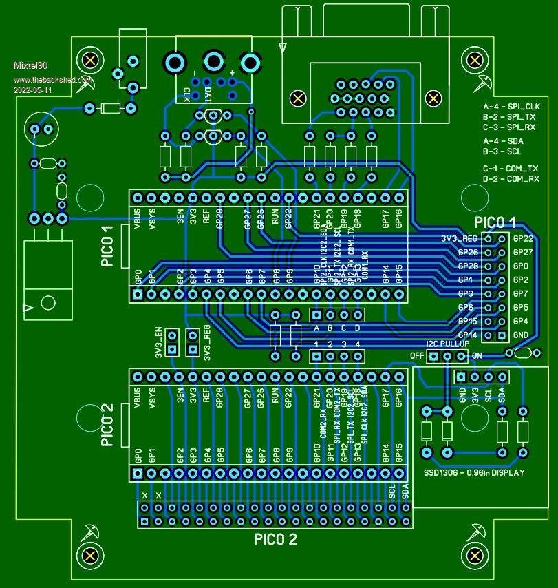 Edited 2022-05-11 05:00 by Mixtel90 Mick Zilog Inside! nascom.info for Nascom & Gemini Preliminary MMBasic docs & my PCB designs |
||||
| Mixtel90 Guru Joined: 05/10/2019 Location: United KingdomPosts: 8913 |
It's grown independent microSD cards for each PicoMite now. And I've still not thought of a use for it. :) Mick Zilog Inside! nascom.info for Nascom & Gemini Preliminary MMBasic docs & my PCB designs |
||||
| robert.rozee Guru Joined: 31/12/2012 Location: New ZealandPosts: 2533 |
well, what you could do is load MMbasic (VGA edition) onto PICO#1, and MMbasic (non-VGA) onto PICO#2. then connect them together via the comm port. now write a simple terminal emulator in MMbasic on PICO#1 as a proof-of-concept that a dual-pico arrangement is viable, and (if) useful. next, think about how you could expand the program on PICO#1 so that it could be instructed to generate graphics. GFXterm does this using a very simple set of around half a dozen commands (similar to VT escape sequences), albeit targeted towards just generating rolling line graphs of data. next, have a look here: http://www.breatharian.eu/hw/picovga/index_en.html this is the code that Peter rolled into MMbasic to create the VGA edition. think about how this code could be changed/configured to generate a 640x360 image, line/dot doubled to 1280x720 (720p 16:9 widescreen). i don't know if such doubling (H and V) would be practical. 640 x 360 x 8-bit-colour would consume 230k of RAM, and allow for 80 columns by 30 lines of text using an 8x15 font. the path would eventually lead to PICO#1 running C code (not MMbasic) that handled the display on one core, while the other core implemented a sort of terminal emulator, geared towards GPU-style functions. for most of the development PICO#2 could run the bog-standard MMbasic binary. later on, one may wish to shift from serial/VT escape sequences on to using SPI and a custom graphics language, at which point some adaption of the MMbasic source code would require some fairly light rework. just an idea...  cheers, rob :-) |
||||
| Mixtel90 Guru Joined: 05/10/2019 Location: United KingdomPosts: 8913 |
I'm *really* surprised you came up with that one, Rob... No point in me looking at that code - I understood very little of it the first time I looked! That's up to you - I do hardware.  I *do* remember that it isn't what you first think. It *looks like* nice, multicolour, hi-res VGA but it isn't. It's very clever, but impractical if you need RAM for anything other than display handling. The path will eventually lead to a severely crippled and slow VGA system - that's my prediction. Probably worse in many ways than what we have at the moment. I'd love you to prove me wrong. :) You'd be *far* better using a Raspberry Pi instead of PICO1 as it can handle a display sensibly. The data link is still a bottleneck though. Mick Zilog Inside! nascom.info for Nascom & Gemini Preliminary MMBasic docs & my PCB designs |
||||
| matherp Guru Joined: 11/12/2012 Location: United KingdomPosts: 11551 |
Ages ago I wrote code to use a Pi-Zero as an HDMI display for the Micromite eXtreme using a special display driver in the ArmmiteH7 (could be replicated in any version of MMBasic). It used an 8-bit parallel I/F and was reasonably quick - nobody ever used it. As soon as you make the H/W environment complicated no-one is interested. Just IMHO Edited 2022-05-11 17:22 by matherp |
||||
| Mixtel90 Guru Joined: 05/10/2019 Location: United KingdomPosts: 8913 |
So much like the SSD1963 as far as the interface goes? Nice. :) It also illustrates the problem of interface speeds, even in parallel. Pity the Pi-Zero is hard to get at the moment. It's a useful wee beastie. :( Mick Zilog Inside! nascom.info for Nascom & Gemini Preliminary MMBasic docs & my PCB designs |
||||
| Amnesie Guru Joined: 30/06/2020 Location: GermanyPosts: 757 |
I think, it indeed does make much sense! There are some points you NEED a second pico, for example in my ECG project, where I must display the graphics AND log the data to the sd at the same time. I have many more applications in mind for this. Since the pico's price tag is a joke compared to other microcontrollers this is the way to go :) Greetings Daniel |
||||
| Mixtel90 Guru Joined: 05/10/2019 Location: United KingdomPosts: 8913 |
Well, folks, we have a release candidate. :) Welcome to the PicoMite Pear (I thought Gemini was just too obvious and, anyway, I got the fun of drawing a pear in Sprint Layout 6. :) ). PPear Construction Pack.zip A bit like the above drawing but it grew a bit. Like they do. If anyone else is thinking of mounting one of these displays in a confined space then use one of the drawings on the web, don't measure one. The one I have is a couple of mm smaller in both directions than any of the drawings! Mick Zilog Inside! nascom.info for Nascom & Gemini Preliminary MMBasic docs & my PCB designs |
||||
| lizby Guru Joined: 17/05/2016 Location: United StatesPosts: 3789 |
Thanks for that, Mick. Don't know if I will ever build it, since I'm not much into VGA, but I just ordered 5 boards from JLCPCB shipped slow boat to Nova Scotia for $6.40USD. Anyone in North America want me to mail them a board when I get them? (Elsewhere, probably cheaper to order themselves than for me to post as a letter.) PicoMite, Armmite F4, SensorKits, MMBasic Hardware, Games, etc. on FOTS |
||||
| Mixtel90 Guru Joined: 05/10/2019 Location: United KingdomPosts: 8913 |
I didn't point it out in the manual, but it's perfectly possible to use a standard PicoMite in the PICO1 position. The VGA output won't work, of course, and the number of I/O pins is restricted, but it will still work and would be ideal for someone wanting a low pin count PicoMite and a full PicoMite on a common PCB. You can turn the keyboard off but you gain nothing as the pins aren't wired out. However, if the keyboard is disabled they are connected to the first I2C port (comms is connected to I2C2) so there may be a possibility for connecting some 5V I2C devices to the PS/2 port. The main reason that PICO1 doesn't have more I/O wired out is that I ran out of space for the length of the connector. The display gets in the way at the bottom and a pcb mounting pillar under the board gets in the way at the top end. For many people it wouldn't have been useful anyway as the pins would have been connected to the VGA pins anyway. I also didn't point out that this board fits the same Hammond case that I used for the PicoGAME. Perhaps I should have. :) *** OFF TOPIC WARNING *** While digging through some junk yesterday I found an old Chicony KB-5916 PS/2 keyboard in *very* grubby condition. Plugged it into a PicoGAME and it appears to work perfectly. So yesterday evening I stripped it down and cleaned it and I now have a lovely 2-tone retro-looking keyboard to play with. :) Not mechanical, but I can live with it. Mick Zilog Inside! nascom.info for Nascom & Gemini Preliminary MMBasic docs & my PCB designs |
||||
| Mixtel90 Guru Joined: 05/10/2019 Location: United KingdomPosts: 8913 |
For those of you who are a little unhappy with bending resistor leads very close to the body, I've just been updating this board to give you an extra 1.27mm on every resistor. It's needed a little creative maneuvering but it's worked - and I think it's neater. :) No other changes. I'll probably post the new version of the gerbers later today. EDIT: Oh, I couldn't resist... I've included an optional JDY-40 just for fun. Powered from the regulator and with a link to enable it, but the TXD, RXD and SET pins can be linked by the user to wherever they like. Unfortunately, if you want to case this board then you have to chop an unused PCB support out if this is included. That's delayed the gerbers until tomorrow. :) Edited 2022-05-24 07:10 by Mixtel90 Mick Zilog Inside! nascom.info for Nascom & Gemini Preliminary MMBasic docs & my PCB designs |
||||
| Rickard5 Guru Joined: 31/03/2022 Location: United StatesPosts: 463 |
Hello Mick : I just got one of the Pico Pair boards, and I'm going First ting in the morning to DigiKey to pick up a few Bits and Bobs to Build her! is there any chance of a pic of a built one to look at ? PLEASE, You be my New best Friend! THANKS Rick I may be Vulgar, but , while I'm poor, I'm Industrious, Honest, and trustworthy! I Know my Place |
||||
| Mixtel90 Guru Joined: 05/10/2019 Location: United KingdomPosts: 8913 |
Not from me - I've never built one. :) It's pretty straightforward though, I think. If you have any problems let me know. Mick Zilog Inside! nascom.info for Nascom & Gemini Preliminary MMBasic docs & my PCB designs |
||||
| JohnS Guru Joined: 18/11/2011 Location: United KingdomPosts: 4336 |
Which board is that? John |
||||
| Mixtel90 Guru Joined: 05/10/2019 Location: United KingdomPosts: 8913 |
The PicoMite Pear. Normal configuration: One PicoMite is a VGA, the other is an ordinary PicoMite. You have options on how you use them. There are linkable headers that allow you to put them on a serial link, using I2C, SPI or UART. The ordinary PicoMite could be used as IO for the VGA one, or the VGA one could be an intelligent display terminal for the ordinary one or they could run completely independently of each other. :) There's a construction pack a few posts up. Mick Zilog Inside! nascom.info for Nascom & Gemini Preliminary MMBasic docs & my PCB designs |
||||
| JohnS Guru Joined: 18/11/2011 Location: United KingdomPosts: 4336 |
Ah - thanks. The spelling threw me! John |
||||
| Mixtel90 Guru Joined: 05/10/2019 Location: United KingdomPosts: 8913 |
Well, Pair sounded too obvious, and using "Pear" gave me the opportunity to draw one as a SL6 macro. :) Mick Zilog Inside! nascom.info for Nascom & Gemini Preliminary MMBasic docs & my PCB designs |
||||
| Rickard5 Guru Joined: 31/03/2022 Location: United StatesPosts: 463 |
Sorry Spelling ain't my Strong Suit, I'm from Texas I may be Vulgar, but , while I'm poor, I'm Industrious, Honest, and trustworthy! I Know my Place |
||||
| JohnS Guru Joined: 18/11/2011 Location: United KingdomPosts: 4336 |
No worries! John |
||||
| lizby Guru Joined: 17/05/2016 Location: United StatesPosts: 3789 |
Mick--I just soldered the headers for the 2 picomites on the Pear and otherwise only ran a wire from GP12 on Pico1 to GP17 on Pico2 and GP13 to GP16 to provide a serial link. I plugged in a USB cable to Pico2 and flashed the firmware. When I tried to flash the VGA firmware to Pico1, I didn't get a RPi drive letter. I unplugged the Pico and flashed it with no problem. When I plugged it back in, I got no flashing heartbeat light. I know you designed this to be powered with the LM1117, but is there something I can do to allow Pico1 to be powered via USB? And if so, do I just need to run a wire from VBUS on Pico1 to VSYS on Pico2 to have them both powered with the one USB cable plugged into Pico1? I've looked at the schematic, but haven't altogether comprehended it. UPDATE: Ok, with a magnifying glass I could see the little tail of a trace which connected GND to 3V3.EN, and with my 3x reading glasses, I managed to scrape through the trace. Now I have a blinking heartbeat led on Pico1. UPDATE2: And with VBUS on Pico1 connected to VSYS on Pico2 I have the heartbeat LED on both PicoMites. Edited 2022-08-09 04:21 by lizby PicoMite, Armmite F4, SensorKits, MMBasic Hardware, Games, etc. on FOTS |
||||
| Page 1 of 4 |
|||||
| The Back Shed's forum code is written, and hosted, in Australia. | © JAQ Software 2026 |
