
|
|
Forum Index : Microcontroller and PC projects : PWM to +/- 10V
| Author | Message | ||||
| Tinine Guru Joined: 30/03/2016 Location: United KingdomPosts: 1646 |
Actual DAC signal: 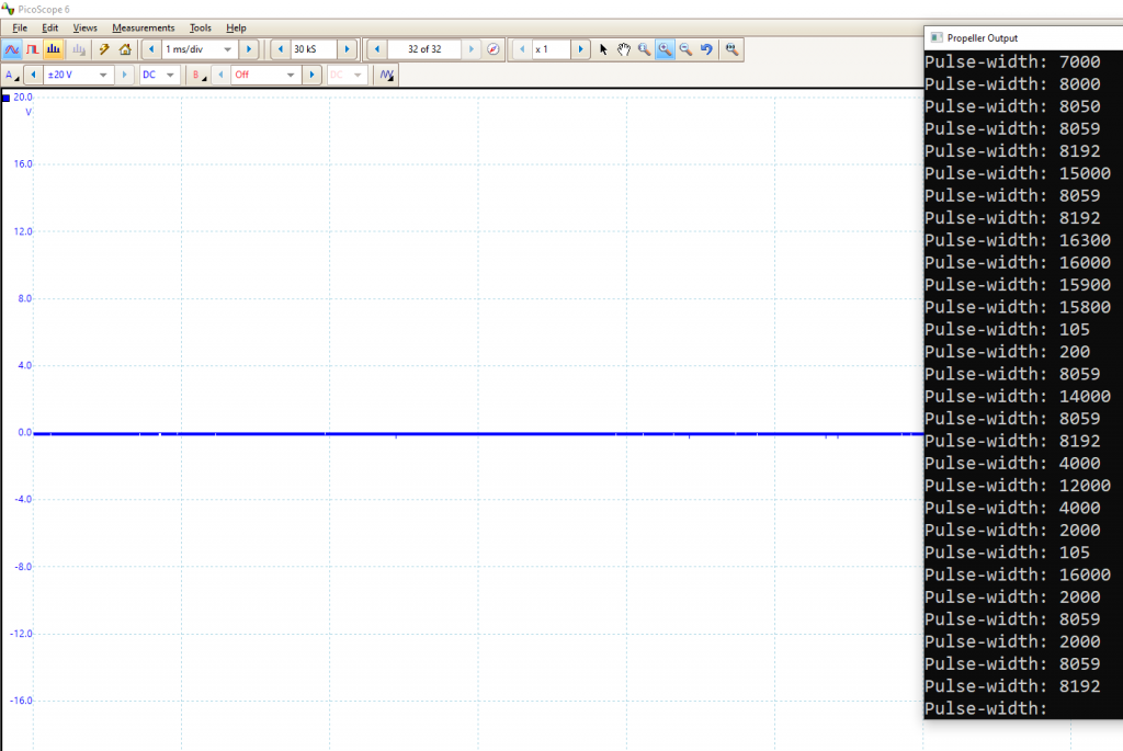 Craig |
||||
| Turbo46 Guru Joined: 24/12/2017 Location: AustraliaPosts: 1639 |
Hi Peter, That 100Hz is the upper 3db point, the input 0.15uF capacitor has an impedance of about 100 ohms at 10kHz so that should be insignificant. Bill Keep safe. Live long and prosper. |
||||
| Tinine Guru Joined: 30/03/2016 Location: United KingdomPosts: 1646 |
Au contraire :) I value any/all contributions. Am about to hack this older prototype to try the various options  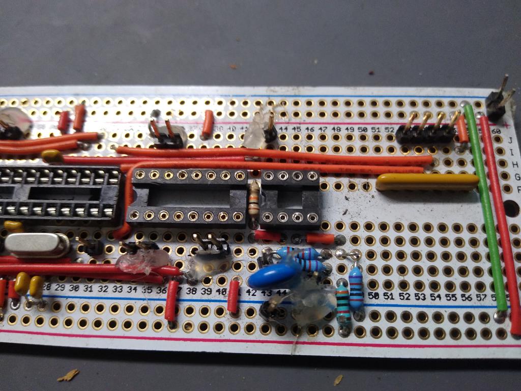 |
||||
| PeterB Guru Joined: 05/02/2015 Location: AustraliaPosts: 655 |
How fast was it going when it hit the truck?  |
||||
| Tinine Guru Joined: 30/03/2016 Location: United KingdomPosts: 1646 |
 Ā Ā Ā ĀIt spent a few days in an actual machine, to prove-out. Didn't trust the headers and so got carried away with the hot-glue gun. Edited 2022-05-17 17:32 by Tinine |
||||
| Volhout Guru Joined: 05/03/2018 Location: NetherlandsPosts: 5058 |
@Tinine, The circuit I proposed uses -12V to bias the output to 0. If you have a noisy -12V, you could inject noise. If you use a picomite, do you use a linear regulator? or the noisy switcher ? If you use a linear regulator, I could redesign the circuit to use the "clean" 3.3V to bias the output to 0. AC coupling is also an option. That removes the need for biasing. The DC is created from the dutycycle, so AC coupling also gives DC stability of the loop. The only problem is that you have a huge "startup" artifact (that may also happen during a "reboot"). Not sure if this is worse than what you are trying to fix. Let me know if you want me to spend time on it. Regards, Volhout Edited 2022-05-17 17:45 by Volhout PicomiteVGA PETSCII ROBOTS |
||||
| Tinine Guru Joined: 30/03/2016 Location: United KingdomPosts: 1646 |
Many thanks but I'm not worried at this stage. When all is said and done, in a live closed-loop scenario, this analogue signal is all over the place because the output of the PID filter constantly fluctuates. The signal feeds a 12-bit ADC that has filtering with the sampling and finally, at the end of the line, there is an electric motor. I have a machine sitting-here, waiting for its new control system...and I'm building the control system. All of the motor-control is being handled by the 8-core Propeller and I have 4 Picomites handling the slower stuff. This is a 6-axis CNC controller and it just so happens that 3 of the axes are tightly controlled/coordinated but the others...not so much. Right now I'm thinking; 3 DACs of one design and 3 DACs of another design and let's see if one is better than the other when on a real machine. Ā Craig Edit: This would never be a problem because none of the high-power stuff is enabled until the controller is in a ready-state. Edited 2022-05-17 18:13 by Tinine |
||||
| phil99 Guru Joined: 11/02/2018 Location: AustraliaPosts: 2610 |
To minimize the "startup artifact" is it practical for the Pico to get it's 3.3V from +1.65V and -1.65V rails? It might require opto-isolators on the inputs. |
||||
| The Back Shed's forum code is written, and hosted, in Australia. | © JAQ Software 2025 |
