
|
|
Forum Index : Microcontroller and PC projects : uMite mx170 44 pin & USB/programmer DIP40
| Page 1 of 3 |
|||||
| Author | Message | ||||
| MicroBlocks Guru Joined: 12/05/2012 Location: ThailandPosts: 2209 |
Just finished laying out a pcb that has a 44 pin MX170 together with my USB-Serial/programmer. All in a convenient DIP 40 sized pcb. 2016-03-10_103056_DipTrace_Schematic_-_UMX170-44.pdf 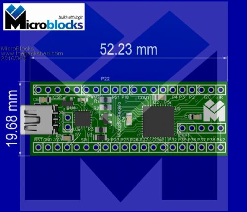
Microblocks. Build with logic. |
||||
| Zonker Guru Joined: 18/08/2012 Location: United StatesPosts: 772 |
Sweet Jean..! Another awesome prototyping tool..! I love these things... They just pop into a vector board, you attach up your project hardware and start writing code...! Makes working with MM Basic easy for everyone... Nice..! Looks great... Are you going to produce a few of these..? Will keep an eye on this one... |
||||
| MicroBlocks Guru Joined: 12/05/2012 Location: ThailandPosts: 2209 |
At the moment it is a schematic and pcb layout. I am waiting for a 44 pin chip and a carrierboard to test if i made the schematics right. :) I think i did, but need to be sure before committing to a real pcb. At the moment very busy to get my manual smd 'assembly line' finished to populate the first two modules. A USB/Serial/PIC32 programmer and a similar board as the one in this post but then with a MX170 28 pins on a DP28 size pcb. I hope to assemble them in batches of 10. Would it be interesting as a kit? I ask because smd parts are used. Microblocks. Build with logic. |
||||
| MicroBlocks Guru Joined: 12/05/2012 Location: ThailandPosts: 2209 |
After some feedback i managed to make the size a little bit smaller so that it is a better size for the pcb manufacturer. (Thanks Mick!) Also added a reset switch, rotated the icsp for the MX170 and moved the icsp for the pic16f1455. The icsp is only needed when you want to connect a pickit3 and use its debug capabilities. For programming you can just use the USB. 2016-03-10_182407_DipTrace_Schematic_-_UMX170-44.pdf 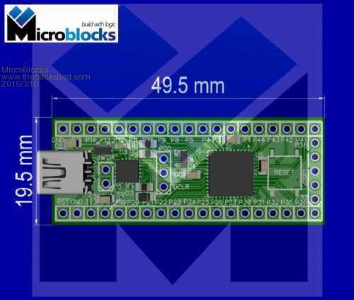
Microblocks. Build with logic. |
||||
| WhiteWizzard Guru Joined: 05/04/2013 Location: United KingdomPosts: 2991 |
@MicroBlocks What package type is the PIC32? Is it a TQFP? It looks different in the images so just checking  |
||||
bigmik Guru Joined: 20/06/2011 Location: AustraliaPosts: 2981 |
GDay Jean, I am glad you were able to squeeze it in, It was a great board before but now it is even better. I will definitely be wanting one or two but as I suspect the chips are QFN packaged I don't think I will be able to solder them so I will have to buy them either fully or partially assembled.. @WW.. I think they are QFN package and as such really need a stencil to apply solder paste and then an oven to cook the chips.. Regards, Mick Mick's uMite Stuff can be found >>> HERE (Kindly hosted by Dontronics) <<< |
||||
| MicroBlocks Guru Joined: 12/05/2012 Location: ThailandPosts: 2209 |
Yes they are QFN. Other packages will not fit on a 600mil wide PCB. I have a whole alternative for breadboarding in development that needs the MicroBlocks to stay within 50x50mm boundaries. I currently use a little hotplate for reflowing and the QFN's reflow pretty easy. No plans on handsoldering except for a single prototype, and i do that with a hot air station. For QFN's i heat them from the bottom side of the PCB. Microblocks. Build with logic. |
||||
| HankR Senior Member Joined: 02/01/2015 Location: United StatesPosts: 209 |
MB, I've heard that for onesies the hot air method is pretty good. Has that been your experience? HR |
||||
| MicroBlocks Guru Joined: 12/05/2012 Location: ThailandPosts: 2209 |
Yes. What works good is to preheat the pcb, i use a small hotplate for that. Switch it on until it reaches about 175 degrees and then switch it off. Put on the pcb and after a minute the whole pcb is then at about 150 degrees and the solder paste start to get a bit thinner. Then a single pass with the hot air with very low air volume otherwise you blow the parts away. :) I also did it with only hot air but that was less easy and i felt i had to heat the qfn's a bit too long. Never had a failure but the shorter the time the better. Before i had the hotplate i just stuck a soldering iron in a piece of aluminum with a drilled hole that matched the diameter of the soldering iron. Homemade mini hotplate. :) Microblocks. Build with logic. |
||||
| MicroBlocks Guru Joined: 12/05/2012 Location: ThailandPosts: 2209 |
I am going to remove the reset button and use the space for something more useful. I mean how many times would you need to press the reset when it is embedded in some box. :) I was thinking about maybe a RTC, FRAM, IR sensor etc. The I2C pins and the IR pin are already on that side of the pcb so it would be easy to route. I often see users needing some way of keeping values even after a restart. A small FRAM would be ideal i think. For an RTC there are so many version and you of course need a crystal and a battery, which will fill up that area quickly. I just measured the area and i think there is enough space for an FRAM and an RTC and an IR sensor. The FRAM could be 32Kx8 bit, no idea which RTC and IR sensor yet. Any suggestions what would be useful to have. It can be a footprint only so that it is an optional part. Microblocks. Build with logic. |
||||
| bigmik Guru Joined: 20/06/2011 Location: AustraliaPosts: 2981 |
Jean, If you can move the USB connector UP a wee bit you can probably fit 2 holes for a RESET jumper.. As to what else in that space? Hmmm, SPI and I2C headers maybe? Regards, Mick EDIT !!!! Maybe swing C6 under the board (assuming it is components both sides) if not I think there is still room to move. Mik Mick's uMite Stuff can be found >>> HERE (Kindly hosted by Dontronics) <<< |
||||
| MicroBlocks Guru Joined: 12/05/2012 Location: ThailandPosts: 2209 |
I will try. I really would like to keep all the parts on one side. Makes live simpler. :) I do not want to have headers (except the ICSP and reset) as this is designed for use on a pcb. If used for prototyping i often have a version where the header pins are available on the top side. This would then allow easy connections without having to use a breadboard. Microblocks. Build with logic. |
||||
| bigmik Guru Joined: 20/06/2011 Location: AustraliaPosts: 2981 |
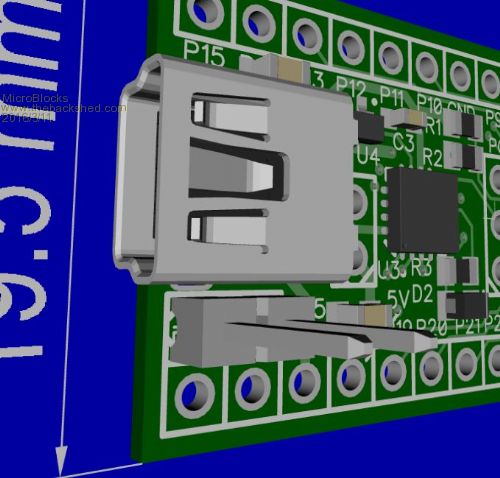
MB, Is is possible to upload a high res (zipped or PDF) of the overlay as it is quite hard to see in the TBS crunched image? I understand about components 1 side, if no others are there then dont put C6 there either.. Also where are R3 and LED? Mick Mick's uMite Stuff can be found >>> HERE (Kindly hosted by Dontronics) <<< |
||||
| MicroBlocks Guru Joined: 12/05/2012 Location: ThailandPosts: 2209 |
Mick, good eye as there was enough space to add a reset jumper. 
I will upload a highres image and link to it. A moment.... 
 Microblocks. Build with logic. |
||||
| bigmik Guru Joined: 20/06/2011 Location: AustraliaPosts: 2981 |
MB, Good eye??? Cant say I am told that too often these days.. 
Mik Mick's uMite Stuff can be found >>> HERE (Kindly hosted by Dontronics) <<< |
||||
| MicroBlocks Guru Joined: 12/05/2012 Location: ThailandPosts: 2209 |
R3 and LED are right below the small pic. I see that the silkscreen still says D2 and that the 3d model is a diode, don't have a 3D model of an SMD led so i used it as a placeholder. Microblocks. Build with logic. |
||||
| paceman Guru Joined: 07/10/2011 Location: AustraliaPosts: 1329 |
Hi Jean, If you're thinking maybe an RTC then a DS3231/2 would be the obvious I'd guess. The firmware for it is in MMBasic, it's accurate, no crystal needed, and you can get temperature from it. 'Only' problem is the battery but maybe a jumper? Greg |
||||
| MicroBlocks Guru Joined: 12/05/2012 Location: ThailandPosts: 2209 |
Yes, i considered them but unfortunately they are in a relative large package. The DS3231 does not fit in the remaining space and the DS3232 is even bigger. Such a pity as they have lots of NC (not connected) pins. I guess most space is used for the internal crystal. Microblocks. Build with logic. |
||||
| bigmik Guru Joined: 20/06/2011 Location: AustraliaPosts: 2981 |
MB, The DS3232MZ is a VERY SMALL 8 pin device I use on my SMD-BP170 however they are not cheap at about $12 Aus .. But it should fit in that space and those who need the accuracy can decide if the cost us worth it or go for an add on board. Mick Mick's uMite Stuff can be found >>> HERE (Kindly hosted by Dontronics) <<< |
||||
| MicroBlocks Guru Joined: 12/05/2012 Location: ThailandPosts: 2209 |
Ouch that is expensive. But if you need it a footprint will be nice. I'll see if i can squeeze it in. Maybe i have to reconsider using the bottom side for optional parts. I might be able to also put in a footprint for a FRAM 32kx8bit chip. Then add a footprint for a IR sensor and then that are is probably as full as can be. :) Microblocks. Build with logic. |
||||
| Page 1 of 3 |
|||||
| The Back Shed's forum code is written, and hosted, in Australia. | © JAQ Software 2026 |
