
|
|
Forum Index : PCB Manufacturing : DIY PCB - Sources of Materials
| Author | Message | ||||
| Andrew_G Guru Joined: 18/10/2016 Location: AustraliaPosts: 871 |
Hi Plover, I forgot to mention that the "bar" at the bottom of the diagram is 50mm long. The border is approximately 43x36mm. Below J2 is J8 - they form a continuous 11 pin female header - on the Cu side) (I don't have such a beast in my Diptrace template) Below J3 is J9 - these are not actually headers but 11 holes at .1" spacing! (its covered in my description above). Subject to the other thread I've just started (here) I will be modifying the design (again) to remove J2 and J8 and put a female header at J3 and J9. OK? Cheers, Andrew (PS - note that "Reset Form" has moved - thanks Gizmo!) |
||||
plover Guru Joined: 18/04/2013 Location: AustraliaPosts: 306 |
There is a bit of action on my part though again having to limit my time to spend on a number of my projects so I do not know when I am going say I have now learnt enough. Interesting exercise to spot changes and correct. My memory looking at a picture then changing page I can no longer remember properly so I have to do side by side comparison and have worked something out that works for me. In the following the connectors and routing is not finished but the spider net has been completed, ie if the schematic is correct then routing is also. On the schematic, I miss the visual female/male header indication which bigmik long ago demonstrated as dots/circles definitely need them back but may have to be a job when building my own libraries. The following is not complete as the 3 pads not below the headers not added but time up. Instead of drilling what about putting in a loop and then remove that when replacing with resistor? First picture shows I am getting close as far as dimesnions, as it is 0.1" grid point based it will be close. I wish I could remember how to turn a picture transparent so the overlay will show much more of the circuit board. On the second picture notice double sided routing because I let the autorouter have a go, takes about less than a second to route and it is a good start. 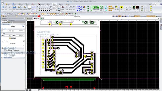 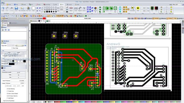 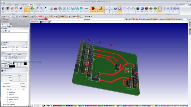  |
||||
| Andrew_G Guru Joined: 18/10/2016 Location: AustraliaPosts: 871 |
Hi Plover, You (and BigMick) have inspired me to have another go at AutoTrax Dex (I am starting from scratch but BigMick's "manual" sure helps). I am still keen to do some DIY PCBs (I now have most of the gear) I think I will progress to gerbers as I begin to "master" the DIY process. WRT to your designs above. Given you are x2 sided you can dispense with J2 and J8. The connections to J3 & J9??(below J3) will depend on your LCD display. BigMick's Serial BackPack is 1:1 for a particular display, my displays require a different connection. I have changed my design so that the connection to J3's top pin is not from Vcc but is now from BigMick's LED pin (currently n/c on J5) - this has a resistor, R2, on the Serial Backpack to protect the LCD. My J7 & J10 are 90 degree indexed male connectors and I'm not yet sure of the gender of the other connectors, except my J3 & J9 will be female to match the male pins on the LCDs. Cheers, Andrew |
||||
| plover Guru Joined: 18/04/2013 Location: AustraliaPosts: 306 |
Ouch, sorry I almost forgot about this little exercise. I have to re-build my hard drive. A job I was not very keen on but the drive I am running this DEX operation is getting in need of some organisation. All up I expect it will take me about a week before I am happy with a new setup. If you have DEX I will post the project and you can load on your DEX configuration. This is one thing I like very much about DEX, you have everything in one folder. To exchange information is just passing one file. I think my next move was to place the 3 pads sitting outside the board and re-route manually so it looks better. Will be interesting to see what you can make out from building further the project. Quite understandable you are keen to try and do the whole process your self, I did some years ago. The idea of getting plated through holes and two layer boards ready made in short time has lured me back. I was going to hand wire my test board will probably take me a day so I am seriously thinking of finishing it off and sent off, doing design work while waiting. Then less than 1 hour putting components from test board on pcb made, appeals to me. Have you got aaccess to the DEX Forum? This way we can exchange projects. The othe perhaps better way if you pm me an email address I can send you a project file.  |
||||
| Andrew_G Guru Joined: 18/10/2016 Location: AustraliaPosts: 871 |
Hi Plover (et al), PM sent. Until I can snaffle my wife's Win10 machine (she has a new Apple thing) I am restricted by my old XP's speed and what it can do with Dex. In the meantime I have composed the following on Diptrace and I'm not far from having a go at etching my own. Then I'll try to compose a x2 sided one to send to China. You will see that it is quite different. I've inverted the HC-12 so the antenna is more central. I've added more headers to access more of BigMick's Serial Backpack's pins, power to the LED now comes from Mick's LED pin (protected by a resistor on his board) rather than Vcc and I've added some pads so I might be able to connect to the other LCD versions I have. 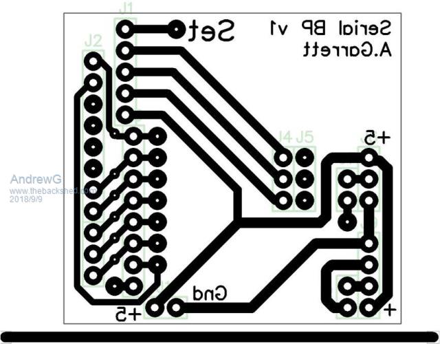 Cheers, Andrew |
||||
| plover Guru Joined: 18/04/2013 Location: AustraliaPosts: 306 |
hi Andrew_G That is looking good, it will do well I expect. It started to think in after sending you the poject, you said XP, for some month this has been abandoned, so you may be on an older version of DEX? If that is the case tell me what version you are on and I will drop back to some of the last DEX version before XP went on retirement. Am I right thinking that an Apple pc you need to run some virtual machine stuff or something? What about keeping an eye open for older pc on Ebay, say about 4 years or older but coming from corporate environment. Those machines are often very good. I am running hp8300 Small Form Factor Elite models built in graphics display, and have added a 24" widescreen cheap end of line Samsung screen. as well as the old 19" ViewSonic VA912. -p |
||||
| Andrew_G Guru Joined: 18/10/2016 Location: AustraliaPosts: 871 |
Hi Plover, yes I assume that I am running an older version of DEX (I'm on 10.237). Don't worry about going backwards as I will get the Win10 machine "shortly". I won't touch the Apple machine - I'll let Jackie play with that. Cheers, Andrew |
||||
| plover Guru Joined: 18/04/2013 Location: AustraliaPosts: 306 |
My understanding is you will be fine with that for your job, but don't spend much time on 3D in the beginning I thought I was ready to get a set of gerbers out tonight but will not happen. I can't pour copper on the bottom side. Anyone runnunning v901 or more ?? I am not sure but it seemed a bit odd. I poured copper on top side fine then I did the bottom side I thought. When I checked the gerbers with built in and at last with outside viewere but no copper pour on the bottom. Any special tricks doing that? I have asked on DEX forum but not much happening there at the moment |
||||
Chopperp Guru Joined: 03/01/2018 Location: AustraliaPosts: 1094 |
@ Andrew Just wondering how you are going with your PCB work & DEX? I've just started using DEX in the Real Schematic mode (was just using artwork) & then playing PCB's. On a fairly big board too. Much fun. It is a great program once you get the hang of stuff. There is so much of it. The recovery bit is very handy. Had it playing silly buggers when I updated a part. Went back to just before it started playing up & continued on from there. Interesting in the 3D mode when you find you have been using the wrong part. Pins pointing downwards instead of upwards & female ones instead of male ones. I just went in & grabbed the first component I found. Slowly getting there. Regards Brian ChopperP |
||||
bigmik Guru Joined: 20/06/2011 Location: AustraliaPosts: 2949 |
Hi Brian, Some of my parts have pins going the wrong way (well vertical positions incorrect) this happened when an update happened 12mths ago.. I need to redo these again.. A lot of parametric parts have been added which sort of supersedes a few of my parts.. But if you have the pins the wrong way you may have placed the part on the TOP (default) and not the Bottom layer (select the part and in properties there is a pull down tab that selects top or bottom.. I am not in front of my PC at the moment so I cannot pinpoint more accurately where this is. Also if you chose Female in stead of Male or vise-versa click the PART BUILDER ICON then select your part.. Select the image that most represents your part (Presume it was a header) then there is a small easy to miss check box that turns the part into male/female types.. Works only on parametric parts and I think ONLY on headers.. There is a similar one for DIP ICs to add a socket in the 3D. My last day of work tonight.. At Midnight tonight (or is that tomorrow morning) I enter the world of the unemployed.. Get used to the fact I now will probably darken the back sheds doors a lot more (still doubt I will catch Grogster�s massive post count though) Retirement here I come.. Woo Hoo. Regards, Mick Mick's uMite Stuff can be found >>> HERE (Kindly hosted by Dontronics) <<< |
||||
| Andrew_G Guru Joined: 18/10/2016 Location: AustraliaPosts: 871 |
Hi all, I'm back on deck after some health issues - all very good now! (There is also the design of a new house bubbling along). My DEX efforts have taken a hit because I still haven't taken over Jackie's Win10 PC (and XP is just too slow). I now have all the gear to make my own PCBs - and will do so! But, BigMik has short-circuited that "learning opportunity" by using DEX for a PCB to connect his Serial Backpack to my 1.8" LCDs (as per the circuit I raised above). When the slow boat docks, and I've made them up, I'll report back. In the meantime I'll leave it to Mick to spruik his gear - but I am one very happy customer. (I trust he'll be distracted by post-retirement celebrations for at least a few days... well done Mick!) Cheers, Andrew |
||||
| Chopperp Guru Joined: 03/01/2018 Location: AustraliaPosts: 1094 |
@ Andrew. Good to here that you are back on deck again & all is well. BTW, DEX is slow on a Quad Core on W10. Hate to think it would be like on an old XP machine @ Mick (Mik) Thanks for the tip on PART BUILDER. I haven't made sense of running it within the schematic yet. Trying to work out why a lot of resistors have half their bodies missing in 3D view.  Will plod along Brian ChopperP |
||||
| bigmik Guru Joined: 20/06/2011 Location: AustraliaPosts: 2949 |
Hi Lads, @Andrew, Glad you are on the up and up.. Yes I havent yet got used to being retired.. It hasnt clicked in my brain that I can forget about work from now on.. Except what the domestic boss has planned for me. As to the PCB I did for you.. It is yours if you want to sell them be my guest. If you run out and there is an interest I will consider getting some made for sale if you are happy with that AND you do not wish to do so yourself. Please post some pics once the 10' tinnie arrives across the tsunami over to AUS. @Brian, If you can email me or post your project here I am happy to have a look at it for you. Kind Regards, Mick Mick's uMite Stuff can be found >>> HERE (Kindly hosted by Dontronics) <<< |
||||
| CaptainBoing Guru Joined: 07/09/2016 Location: United KingdomPosts: 2170 |
Something I have had a degree of success is to produce my own etch resist boards from copper clad sparayed with cheap black aerosol paint then laser etch the tracks. This got me started: https://www.youtube.com/watch?v=1hFNj86L7sk |
||||
| Chopperp Guru Joined: 03/01/2018 Location: AustraliaPosts: 1094 |
@Mick Thanks for the offer. Much appreciated. Still a work in progress at this stage. Got a lot more work & learning to do before it is anywhere near ready. From a post by Grogster in another thread, there are quite a few things to get right, such as hole sizes etc. I was working from home for a number of years before I retired (made redundant) 2 years ago. Not much changed really . I wasn't getting out much for the first year. Things got better when I started playing trains. I'm sure you won't stay home & vegetate.Edit. It will eventually be a fairly big board. Brian. ChopperP |
||||
| The Back Shed's forum code is written, and hosted, in Australia. | © JAQ Software 2025 |
