
|
|
Forum Index : Electronics : another inverter project
| Page 1 of 3 |
|||||
| Author | Message | ||||
| nickskethisniks Guru Joined: 17/10/2017 Location: BelgiumPosts: 481 |
Hello, I will post my progress on the oz inverter here. I just ordered the pcb's for the Ozinverter. In the meanwhile I will gather all the components. So, I plan to use 3 stacked toroidal cores, the dimensions of one core: 211mm outer diameter, 80mm inner diameter and height is 60.5mm. They are from isolation transformers and were rated at 2000VA. They were wound with 177 turns, so 1.3V/turn. But that gave me +/-20W iron losses. I want to aim a lot lower, the formula that I had found here gave me ((65.5*60.5)/2800)) 1.42V/turn, I think the quality of the iron is rather poor. So I need to do some testing before, 1 core weighs about 15.8kg. I was planning to use 3.55mm diameter wire (9.6mm˛) for the 230V side. I was hoping to get around 10kva out this inverter for 30min. Most people suggest 10cm for the inner diameter, but will the 80mm suffice? I could buy iron cores from a forum member, but I was hoping to work with the cores I already have. |
||||
Madness Guru Joined: 08/10/2011 Location: AustraliaPosts: 2498 |
You may find the 3.55mm wire difficult to wind, if you get thinner wire and put a number of them in parallel it will be a lot easier. 1.6mm is easy to work with, even the increase to 2mm is quite a bit harder to work with. 80MM is going to get very tight, with 3 cores though your number of turns is reduced so that will work in favour. If you need to you could unwind some of the centre of the core to increase the hole size. There are only 10 types of people in the world: those who understand binary, and those who don't. |
||||
| Clockmanfr Guru Joined: 23/10/2015 Location: FrancePosts: 437 |
Hi Nick, Yes those cores sound good. If you unwind the core from the centre and increase your core internal diameter to 90mm diameter, 2 cores stacked would be okay for a 6kW. And the 50mm/2 cable for your primary will fit the centre hole. If you have 4 in hand of say 1.8mm diameter enamelled copper for the secondary. 2 cores would then give you a active cross section of 7320mmsq, and using Oztules formula 7320/2800 = about 2.61v per turn. 240v/2.61 = about 92 turns for the secondary and therefore 92/8 = 12 turns for the primary. If you use the ratio of 9 turns secondary to 1 turn Primary then its 11 turns primary. We wind the secondary first. Personally I would wind on 105 turns temporary secondary onto your 211 x 90 x 121mm core, then a temporary primary of 12 turns. and see what you are getting. You are looking for a voltage on the primary of between "28-30 for the 8010 chips for a nominal 48v system." All this information and further calculations and a better explanation can be found on page 18, 19 and 20 of the OzInverter book. I trust this helps.? Everything is possible, just give me time. 3 HughP's 3.7m Wind T's (14 years). 5kW PV on 3 Trackers, (10 yrs). 21kW PV AC coupled SH GTI's. OzInverter created Grid. 1300ah 48v. |
||||
| nickskethisniks Guru Joined: 17/10/2017 Location: BelgiumPosts: 481 |
Thank you for the advice! I did some testing of the transformers: I don't have a variac so used a bulb in series with the windings. I tested a transformer with the 230V primary and the secondary was 2 times 115V, I think the primary had 176 turns (wound with 2mm wire) and the secundary had 91 turns each (wound with 1,8mm wire). The other 2 transformer were wound with 1,8mm wire. The voltage was measured directly on the windings, current with a 2A clamp meter. primary 220V in 0.057A P0 = 12.54W 1 turn gives 1.249V primary with 1 secondary in series 232V in 0.022A P0 = 5.10W 1 turn gives 0.874V primary with 2 secondary in series 233V in 0.012A P0 = 2.796W 1 turn gives 0.652V On the internet I've found some formula to rate a transformer, P = (cross section x 1,3)˛ , if I use 2 stacked transformers this would give me: P = (6*6*2*1.3)˛ = 8760W (VA?) for now this will be enough. So I will follow the given advice. Since lights and sockets are isolated from each other @ my place, I will make 2 inverters. One with one core, the other with 2 cores. I will try winding the secondary for the big one with 3,55mm wire, the primary will be wound with many smaller wires, we will see how that will work out. I hope to make the smaller inverter with verry low idle current. |
||||
| Madness Guru Joined: 08/10/2011 Location: AustraliaPosts: 2498 |
I would try a sample of that 3.55 wire before you commit to it, you have to do a lot of turns for the secondary and 4 times as many corners. There are only 10 types of people in the world: those who understand binary, and those who don't. |
||||
| nickskethisniks Guru Joined: 17/10/2017 Location: BelgiumPosts: 481 |
Ok, It will be a slow build..., I'm to bussy with other stuff... In the meantime I received the ozboards and I did solder a few components, there are some things that needs to be ordered first. I did a sample and I found the 3.55 wire rather soft/bendable. On the left the transformer has now +/- 356 secondary turns, and 52 primary turns ( needs fine tuning during testing). The primary will be good for 40A. It will have low idle current, we will see how that turns out, at least I have a testing transformer. @ the right you can see the 42kg of 3,55 wire, don't ask...  . . As you can see the 2 transformers are stripped, I just need to make the centerhole wider before I epoxy them together. I need to figure out how to cut the centerhole, suggestions? 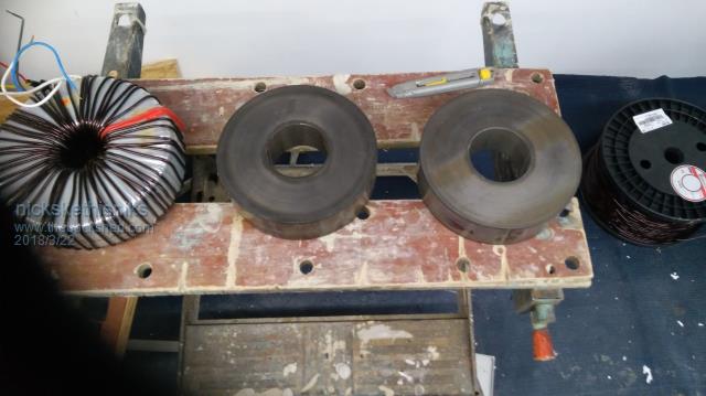 |
||||
| Madness Guru Joined: 08/10/2011 Location: AustraliaPosts: 2498 |
If those core are wound Silicon Steel strip all you need do is unwind enough turns to increase the hole size as required. There are only 10 types of people in the world: those who understand binary, and those who don't. |
||||
| Clockmanfr Guru Joined: 23/10/2015 Location: FrancePosts: 437 |
If you look closely in the centre you will see the end of the coil is spot welded, normally just one spot weld, I have seen 2 spot welds sometimes. Or with the Chinese cores I have seen just some strong tape. Just use a sharp blade to prise open the first winding in the centre a bit, then use a screw driver to force the spot welding apart. When you have the correct internal diameter for the centre hole, just make sure you have no sharp edges, and just use tape to keep the end in position. Everything is possible, just give me time. 3 HughP's 3.7m Wind T's (14 years). 5kW PV on 3 Trackers, (10 yrs). 21kW PV AC coupled SH GTI's. OzInverter created Grid. 1300ah 48v. |
||||
| nickskethisniks Guru Joined: 17/10/2017 Location: BelgiumPosts: 481 |
Hi, I'm having troubles finding out wich component the 1n101 thing is, it's sort of a diode? , it is near the bt169 thyristor. Anyone that has a clue? Can I swap the fr107 diode for UF4007, the pdf says it's better. thanks |
||||
renewableMark Guru Joined: 09/12/2017 Location: AustraliaPosts: 1679 |
Hahahahahaha Clockman board right? I had the same problem, the part isn't in the parts list, but it's printed on the control board. I emailed Clockman, he said it's just a diode for the LED. I think he said pretty much any diode will work, from memory I fitted a 1n4007, hope that works.  Dunno about the FR107 Cheers Caveman Mark Off grid eastern Melb |
||||
| Madness Guru Joined: 08/10/2011 Location: AustraliaPosts: 2498 |
FR107 is a fast acting Diode. There are only 10 types of people in the world: those who understand binary, and those who don't. |
||||
| nickskethisniks Guru Joined: 17/10/2017 Location: BelgiumPosts: 481 |
Had some time to do the epoxy thing to join the 2 cores. What I need to do now ( says the "manual") is the wrapping with mylar, I'm not looking forward to it. So I will skip this part, what I will do next is put on an extra coating with expoxy instead. Mine Is rated to 130°C(after a few hours in the oven) so I see no problems there and it will save me some time. Next time I will post pictures. |
||||
| Madness Guru Joined: 08/10/2011 Location: AustraliaPosts: 2498 |
Wrapping with Mylar is not difficult, I used an empty solder spool and wound the Mylar on it with a drill. Probably takes about 15 minutes to wind it on. There are only 10 types of people in the world: those who understand binary, and those who don't. |
||||
| Solar Mike Guru Joined: 08/02/2015 Location: New ZealandPosts: 1228 |
Quick question: Where do you purchase this stuff, other than removing off an existing transformer; no one in NZ sells it, only stuff that is readily available is the sticky backed version. Cheers Mike |
||||
| Madness Guru Joined: 08/10/2011 Location: AustraliaPosts: 2498 |
I don't know Mike I have had no luck finding it either and am using the stuff I have recovered. Clockman may have found a source for it. There are only 10 types of people in the world: those who understand binary, and those who don't. |
||||
| Clockmanfr Guru Joined: 23/10/2015 Location: FrancePosts: 437 |
Mylar is important to protect the copper enamelled windings from shorting on the metal core and each other. It's especially important if you are using this Inverter long term, 10 years later and that core will have heated up and down many many times. The copper enamelled wire insulation is not that strong. Also the mylar slightly shrinks when heated up so will keep the windings nice and tight. These folk are very helpful, and will send..... I only wanted 800 meters but had to buy 1600 meters. Your requirement is below our MOQ, I can offer the following at minimum order value. Mylar A, 50 micron 2 x 20mm x 800mtrs (approx. 2.34kgs): Ł25.00 Lead time: 3-5 days Carriage to France: Ł25 Kind Regards, Simon Kaminski UK Insulations Ltd, Syke Mill, Belthorn Road, Blackburn, BB1 2NN T: 01254 264499 F: 01254 279284 http://www.ukinsulations.co.uk/ Everything is possible, just give me time. 3 HughP's 3.7m Wind T's (14 years). 5kW PV on 3 Trackers, (10 yrs). 21kW PV AC coupled SH GTI's. OzInverter created Grid. 1300ah 48v. |
||||
| nickskethisniks Guru Joined: 17/10/2017 Location: BelgiumPosts: 481 |
Hi there, Getting closer to testing each week now :). Still waiting on the adapter boards for the heart of my inverter, the chinese folks canceled my order.... So once they arrive I'm ready for testing. So the plan was to aim for 130 secondary windings, but ended up with about 150 turns, spread in 2 layers. The second layer had more turns because my wire was to long, I just kept winding. The first layer of turns was ok, I made neat turns, next time I will do the job better but it was fine. The second layer was more difficult because there was no plane surface anymore so the wires did not what I wanted, but I can live with the result. So far no short circuits. The core had an epoxy layer on the outside I reinforced it with glassfibre. Then there is some electrical tape on the edges and wraped in capton tape. Next time I'll put more or thicker electrical tape on the edges. Or like sugested, using the mylar tape wich is much stronger! 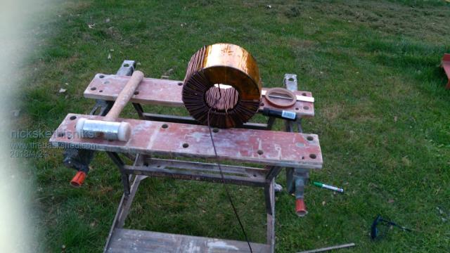 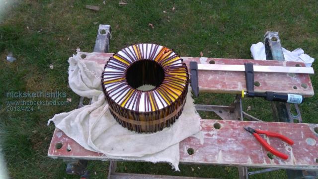 Finished the first layer. It took me about 1.5-2 hours. Finished the secondary, the second layer took me about 3hours to complete...  Last photo you can see the transformer had a thick epoxy layer, ready for the primary, maybe I add a layer of capton tape. Stil wondering wich wire to use for the primary, I still got a lot of the Original wire. Testing results: 225V 0.046A 10W (1.484V /turn primary) 235V 0.048A 11.5W So it was better then I hoped, after 63turns I had 0.136A @ 118.4V, so imagine that @ 230V! Only downside is that I need more primary turns... I've got an opening of 75-80mm left for the primary so I hope this will be enough. I hope it is ok to post the amount of photo's. |
||||
| Madness Guru Joined: 08/10/2011 Location: AustraliaPosts: 2498 |
I am not sure if I am reading this right but if the 2 windings you have put on are both to be your secondary and connected in parallel they must be exactly the same number of turns. Plenty of photos is good. There are only 10 types of people in the world: those who understand binary, and those who don't. |
||||
| johnmc Senior Member Joined: 21/01/2011 Location: AustraliaPosts: 283 |
Good Day, About 2 years ago bought 2 large rolls ,minimum order, of mylar tape from a electrical rewinding wholesaler in from Sydney but I cannot find their address. cheers john johnmc |
||||
| nickskethisniks Guru Joined: 17/10/2017 Location: BelgiumPosts: 481 |
I forgot to mention I use the windings in series, I use new 3.55mm (9.9mm˛) wire so no need to parallel them. |
||||
| Page 1 of 3 |
|||||
| The Back Shed's forum code is written, and hosted, in Australia. | © JAQ Software 2026 |
