
|
|
Forum Index : Electronics : Micro controller driven Warpverter
| Page 1 of 10 |
|||||
| Author | Message | ||||
| poida Guru Joined: 02/02/2017 Location: AustraliaPosts: 1480 |
And so it begins. This will be where Mark and I document the build of a Warpspeed inverter. (shh, I have not told Mark yet. Maybe he won't want to participate.) I have completed bare bones code to drive a 4 transformer Warpspeed design inverter. I chose to use a micro to do the work so that I can synchronise to mains AC and to avoid building a complex driver board. The micro chosen is again an Arduino Uno. There is enough on the Uno to permit the 4 inverter drive signals (4 x 2 bits I/O), and the mains sync input plus 2 ADC channels, one of which will be used for voltage feedback. It can be extended to 5 inverters if we want. How the code works: first set up a 1/2 sine wave lookup table, 200 entries for the 1/2 cycle. The table goes from 0 to 40 and back to 0. Then have an interrupt running, at 20kHz. Each time it runs, it chooses a value from the sine lookup table, and increments the counter for next time. With 200 entries for a 1/2 wave, and a bit of logic to do it all again the next 1/2 wave, we have a 50Hz sine wave, when looking at the value stored in the lookup table. (I sent this value out to an external DAC and I got a lovely 50Hz sine wave.) Next, we make a table to be used to quickly obtain the bipolar drive needed for this combination of 4 inverters. Warpspeed invented a curious thing indeed. I needed to think in "trinary" to get me 'ead around it. This lookup table lets us get the 4 inverter drive signals for any voltage from 0 to 40. This is real fast code. The 0 - 40 is good for working out how the code functions. NO need to worry about 240V now. (+/-1, +/-3, +/-9, +/-27..) The inverter drive data is then asserted on 8 I/O pins, D4 - D7 and ADC0 - ADC3 That's it, essentially. I have my usual mains sync code running on each detected edge coming in on D2. It trims the 20kHz increment code a little one way or the other, to make the output sine align with the edge pulse. It works perfectly, as in nanoverter code. Output AC voltage will be controlled easily by inverse scaling the above sine 1/2 wave table value, in integer maths, by whatever the inverter DC voltage is. Total code once loaded into the Uno is less than 4K. The max the Uno can take is 32K. Lead into the Uno the DC Bus voltage sample, and lead out one ground and 8 inverter drive wires... job done. Upon boot, it immediately runs, outputting a sinewave, starting at zero. 2019-03-27_141042_warp_1.zip wronger than a phone book full of wrong phone numbers |
||||
renewableMark Guru Joined: 09/12/2017 Location: AustraliaPosts: 1679 |
Jeez, you don't muck around mate. Now we just need to talk Tinyt into designing the boards.  OK so.... torroids. I have a double stacked pair of 3kw's. That has 128 turns on 4 secondaries, primary so far is 14 turns of 70mm2. I do have plenty of that 70mm so can wind on as much that will fit, it wont be pretty though, reckon only 6 more will fit. I can get some 25mm2, that should still carry 100 amps, or use 50mm2 No 2 torroid I have an unmolested 2kw aerosharp. No 3 torroid I have an unmolested 2kw aerosharp. No 4 Will pick up a 1kw aerosharp. Cheers Caveman Mark Off grid eastern Melb |
||||
LadyN Guru Joined: 26/01/2019 Location: United StatesPosts: 408 |
yes! wooohoo! I still would love you to consider the ESP32 but I will port it anyways |
||||
Timbergetter Regular Member Joined: 08/10/2018 Location: AustraliaPosts: 57 |
Could I please ask what is the rationale for going with a half wave table rather than a quarter wave table? As I see it, all the last half of your current table can be derived from first half with possibly negligible computational overhead. Looking forward to progress on this topic. |
||||
| poida Guru Joined: 02/02/2017 Location: AustraliaPosts: 1480 |
I don't mirror a quarter wave table since I am lazy and have heaps of memory available. I reuse the 1/2 wave table though. There are a lot of cpu cycles spare in the case of the Uno code. The main 20kHz interrupt takes about 10us of the maximum allowed 50us So there is about only 20% cpu cycles used to run the inverter. wronger than a phone book full of wrong phone numbers |
||||
mackoffgrid Guru Joined: 13/03/2017 Location: AustraliaPosts: 460 |
Guys, I put this together today and was surprised that Poida was working on his own code (and not surprising he pipped me) The code is based on STM32duino. The code has not been tested at all - compiles ok, and was done to suit the little PCB that I did the $10 power scope on as it has a convenient 8 bit data bus. It is only an exercise and I have no intention of moving away from the eprom based clock board for a real inverter. If anyone is interested I can tidy it up more (comments) and debug it otherwise I won't be in any hurry since we have a nano version. 2019-03-27_182832_stm32_StepInverter.zip |
||||
| Warpspeed Guru Joined: 09/08/2007 Location: AustraliaPosts: 4406 |
Ah ! We move at lightning speed from the steam age, into the jet age, great stuff guys. Well done. Cheers, �Tony. |
||||
| renewableMark Guru Joined: 09/12/2017 Location: AustraliaPosts: 1679 |
Lol, they have been inspired by you Tony, now it's Warpspeed. Edit, yes pun intended. Cheers Caveman Mark Off grid eastern Melb |
||||
| wiseguy Guru Joined: 21/06/2018 Location: AustraliaPosts: 1297 |
I have my version of a nano controller board back and mostly assembled, my super fast FET boards as a work in progress and with the fast switching edges I am experiencing harmonics all the way from Dc to light, instability, glitches etc. And then I look at Tonys multi stepped sinewave through tired eyes - that help make it an even cleaner looking sinewave, no glitches, noise, ringing, smoke - how boring, Can I buy a board when its done............ I havent given up on mine still busy fitting snubbers and removing my mistakes - it may even work well when finished - I have seen some glimpses of promise and success, but I am growing to like the stepped inverter concept more and more. If at first you dont succeed, I suggest you avoid sky diving.... Cheers Mike |
||||
| Warpspeed Guru Joined: 09/08/2007 Location: AustraliaPosts: 4406 |
Every home should have more than one inverter..... Poida, how often does your software look at the dc input voltage ? Is it every single step, or every whole 20mS cycle or what ? Mine looks only every 40mS and its very important that the measurement must be noise free, which is why I used a dual slope integrating D/A. If the measurement captures a glitch it could apply a massive voltage correction for two whole cycles which might be quite "interesting". If you are measuring every single step, its going to have an incredibly fast response and a single event may not be at all serious, if the next following step is corrected. Cheers, �Tony. |
||||
| renewableMark Guru Joined: 09/12/2017 Location: AustraliaPosts: 1679 |
OK I'm not too great on calculating, so I'll need a bit of help with the torroids. Batt volts is a 48v bank, my normal LV cut off for bank is 46.5, but it's never actually cut off in 6 months use, I think the lowest it's been under a heavy load was the low 47's. No 1 toroid is already made with 2x3kw cores stuck together 128 turns of 4 layers secondary. 14 turns currently on primary. So how many extra will I need on the primary? No 2 torroid will be a 2kw core, I'll most likely rewind this from scratch, so what would be the optimal turns and number of layers for secondary and primary? No3 & 4 I picked up a few smaller ones today. 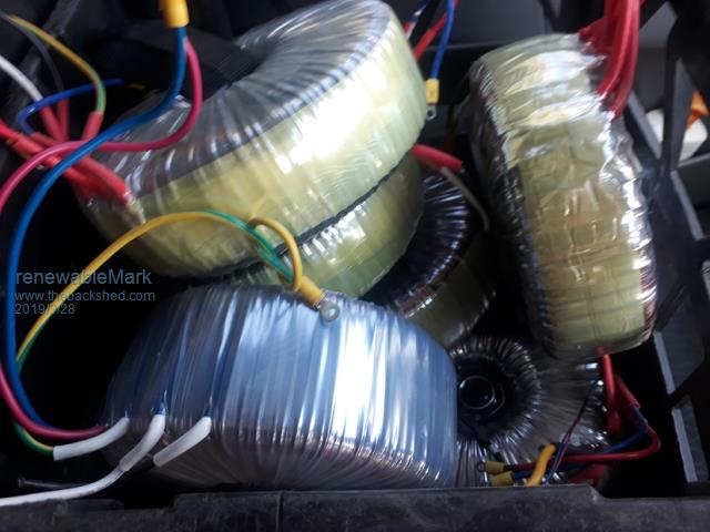 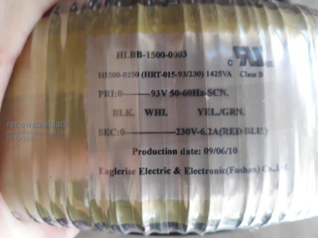 Cheers Caveman Mark Off grid eastern Melb |
||||
| Warpspeed Guru Joined: 09/08/2007 Location: AustraliaPosts: 4406 |
Mark, lets do these one at a time. If you design all of your transformers to have a 44.0 volt minimum, that will allow for a little bit of extra voltage margin for voltage drop in the mosfets and wiring. With a 25 turn primary, the secondary voltage will be 44v x 128/25 = 225.28v About 35mm squared wire should be about right for the primary. Cheers, �Tony. |
||||
| LadyN Guru Joined: 26/01/2019 Location: United StatesPosts: 408 |
I do not believe this code does line regulation. It seems to assume that the input voltage lies stable at 40V, from a cursory glance. I plan to dig deeper next week but maybe we should discuss the line regulation in a separate thread, otherwise this thread could end up with multiple "sub threads". For example, I don't intend to derail the discussion above about the transformer design |
||||
| renewableMark Guru Joined: 09/12/2017 Location: AustraliaPosts: 1679 |
Warp, that torroid is actually 127 turns on the sec, not 128, which doesn't work out as well @ 223.52v I spose where they come out at the side I could add more wire and make another turn, or swap out the other torroid that is in the machine running the house, that one is 128. Cheers Caveman Mark Off grid eastern Melb |
||||
| Warpspeed Guru Joined: 09/08/2007 Location: AustraliaPosts: 4406 |
It makes things a whole lot easier if we can design all of our transformers to have whole volts on all of the primaries and all of the secondaries. When you strip off the existing primary, just add one extra turn to the secondary to get back to 25/128 and a 44.0v minimum voltage. It can be just one extra turn of big fat wire. That should not interfere too much with the primary that goes over it. The other alternative would be 24/127 and make our minimum voltage 42.5v for the other three transformers. Both solutions are workable. Cheers, �Tony. |
||||
| poida Guru Joined: 02/02/2017 Location: AustraliaPosts: 1480 |
In regards to line regulation: I just did a quick proof of concept and dumped the code here. Just now I added DC supply regulation. It has not increased the time spend in the main 20kHz interrupt by any significant amount. It's still 10uS according to my DSO. And a few more comments. 2019-03-29_093722_uno1.zip Warpspeed: Is this correct? // This is a 1,3,9,27 ratio tranformer build. Total voltage out is 40 units. // we want 240V, so it's 6V/unit at full power // Good inverter design has some primary voltage headroom, maybe 20% // so let's set normal low voltage cutoff at 48.5V, this will be our 80% power setting // 80% of 40 units = 32 units. // 48.5V primary = 34.3V AC RMS primary voltage. // 240V needed, can only drive it to 32 units. This means 240/32 V per unit = 7.5 V/unit // the transformer secondary output voltage will be // 7.5 x 1, 7.5 x 3, 7.5 x 9, 7.5 x 27 // 7.5V AC rms, 22.5V AC, 67.5V AC, 202.5V AC // All secondary windings need to be capable of the intended AC output current. // Wind the primaries to suit the above output voltages... wronger than a phone book full of wrong phone numbers |
||||
| Warpspeed Guru Joined: 09/08/2007 Location: AustraliaPosts: 4406 |
I attacked the problem in a different way. Assume initially that the required nominal inverter output voltage to be 235v rms (or 333v peak). Secondaries must have 1:3:9:27 voltage ratios (which all add up to 333v peak). We can conveniently round out all the secondary voltages to integer values to give a much more convenient basis for calculating the transformer turns ratios. Secondaries 8.33v : 25v : 75v : 225v which add up to 333.33v or 235.7 v rms. The transformers operate under square wave voltage drive conditions and the minimum dc input voltage will give us the peak primary voltage direct. If we assume for this example a 40v minimum input dc voltage. Transformer turns ratios will then need to be: 40/8.33 40/25 40/75 40/225 Regarding line regulation. At our minimum design input voltage we are going to need all of our available steps, 40 up, 40 down, plus a zero step in the middle to reach a 235.7v rms output at our minimum design input voltage. Above our minimum input voltage, we use fewer steps or narrower steps, because our steps will be taller at a higher available input voltage. At anything more than the absolute design minimum input, we could if desired, reach a higher final output greater than 235.7v Its then up to the control system software to throttle back the output voltage to whatever we really require. Cheers, �Tony. |
||||
| LadyN Guru Joined: 26/01/2019 Location: United StatesPosts: 408 |
This question likely betrays my complete lack of understanding of the physics behind the warpverter but as the input line voltage increases and we skip steps, wont the THD increase? |
||||
| Warpspeed Guru Joined: 09/08/2007 Location: AustraliaPosts: 4406 |
No, because the steps slowly increment up to a peak voltage, then decrement back to the zero crossing. We don't actually skip any steps. If the steps are small then there will be a greater number of steps to span the distance between zero crossing up to the peak. If the input voltage is higher, the step height is greater and we need fewer steps to reach the peak. The waveform does look a bit more coarse and ragged, and the THD does degrade slightly, but not by as much as you might expect. With all 81 steps the THD is less than one percent. With only twenty at twice the dc input voltage steps its more than 1% but less than 2%. Its still has less distortion than you might measure straight from the grid. All the THD produced is mostly just the highest odd harmonics, which can be fairly readily filtered out. The problem is more theoretical than practical. Cheers, �Tony. |
||||
| poida Guru Joined: 02/02/2017 Location: AustraliaPosts: 1480 |
I have time to try and compile for the Blue Pill. #include <Streaming.h> no such file.. Which board (in Arduino IDE world) did you use to create this? wronger than a phone book full of wrong phone numbers |
||||
| Page 1 of 10 |
|||||
| The Back Shed's forum code is written, and hosted, in Australia. | © JAQ Software 2026 |
