
|
|
Forum Index : Electronics : Circuit to flash one LED then the other at about a second each.
| Author | Message | ||||
| Pete Locke Senior Member Joined: 26/06/2013 Location: New ZealandPosts: 182 |
Mike is correct in pointing out the zenners were left off the circuit, and should be included. Otherwise...."POOF" after the first flash. I like Mikes simpler, but very clever discrete circuit. His thought process is above what I came up with and I'm going to breadboard one up just to tinker with. Good luck with the project. Cheers Pete'. |
||||
| bob.steel Senior Member Joined: 27/02/2020 Location: AustraliaPosts: 188 |
I find that with the boards I have got up and running controlling the flash rate is difficult . One flash in one second or slower is what I'm after for its effect but there is a lag in these so that the one light does not switch off so the flashes are blurred . Well thats what I have found so far . Yours are more clearly defined flashes in your video so I used that as a design practice with eagle . I think I will breadboard it and try also now with the zenners. |
||||
| wiseguy Guru Joined: 21/06/2018 Location: AustraliaPosts: 1206 |
Ok I fess up, there is something in my circuit that I don't like and it needs to be fixed or you could end up with 3 legged resistors as Bob has found out. If you follow the current path when a power FET is on, at the instant that the smaller transistor turns on (to turn off the FET), there is an unintended high current path via the source of the FET via the zener into the small transistor. (see original circuit a couple of pages back) So it is a race whether the FET turns off first or the zener or and the 1N914 or and the small transistor curls up their toes first. Admittedly the FET turns off in probably 100 - 200nSecs but damage/stress may have occurred. I know my breadboarded circuit worked fine but I did have one instance of a 3 legged resistor due to a wiring error (and probably this high current path). The circuit improvement is posted below, I placed a 1K resistor in series with the Zener (R5 & R6), now the current is limited to ~ 25mA, the resistor adds about another volt to the zener voltage so suggest no higher than a 16V zener is used. C1 & C2 charge up fully in less than 250mSecs (for 47u) so operation is essentially unaffected. If you dont like the flash rate, increasing the value of resistors R3 & R4 or capacitor values C3 & C4 will slow down the flash rate & vice versa to speed up. There should be no slow turn off of the LED current - it is instantaneous, so a slowly turning off LED has another reason why, faulty component or wiring error. So Bob, if I caused you some grief with this oversight - sorry, but look at all the experience you have gained in the process  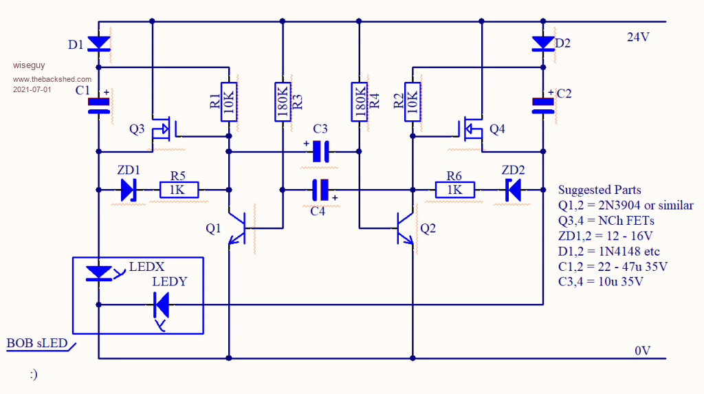 Edited 2021-07-01 12:58 by wiseguy If at first you dont succeed, I suggest you avoid sky diving.... Cheers Mike |
||||
| bob.steel Senior Member Joined: 27/02/2020 Location: AustraliaPosts: 188 |
I have had a ball thank you and its still going .Looking for just the right flash rate to make best use of the blue flash . It will add an instant worry factor now for any intruders. I appreciate your efforts and will add to the circuit and play a bit more. Thank You. Edited 2021-07-01 13:07 by bob.steel |
||||
| wiseguy Guru Joined: 21/06/2018 Location: AustraliaPosts: 1206 |
I forgot to add, if you use Pete's circuit 1 or 3 with the Mosfets & zeners, they should also have the 1K resistor added in series wih the zener for the same reasons. Edited 2021-07-01 13:29 by wiseguy If at first you dont succeed, I suggest you avoid sky diving.... Cheers Mike |
||||
| Pete Locke Senior Member Joined: 26/06/2013 Location: New ZealandPosts: 182 |
.....So are you saying that you want a pause in between the two light flashes, i.e, one light flashes, then a delay, and then the other flashes in a repeat cycle? The circuits presented here will switch instantly between the two lights. If a delay is wanted, that will be a different, but not difficult design. Let us know if that's the case. The main thing is you can use your N-Chanel FET's as you wanted. Cheers Pete'. |
||||
| bob.steel Senior Member Joined: 27/02/2020 Location: AustraliaPosts: 188 |
Thanks Pete , No its fine as you have it but I want to play with it to get maybe a 2 second white light then a 1 second blue pulse . I'm working up something for its visual effect in a security lighting system for shops and the like . If I get this going as I seek then I might add a red for effect too. Flash white on and then a red and blue one second each . That type of thing. The important work you have done already thanks and I am just playing with it now . I got warpspeeds ,Mikes. circuit up and running and put a video here I'm still getting transistors blowing though . Its not a worry with this new tester but I must have put in 5 new pairs to date.Got about 90 left though. Edited 2021-07-04 16:26 by bob.steel |
||||
| Warpspeed Guru Joined: 09/08/2007 Location: AustraliaPosts: 4406 |
Red white and blue. Bob we will have to stand at attention and salute the flag  Cheers, �Tony. |
||||
| bob.steel Senior Member Joined: 27/02/2020 Location: AustraliaPosts: 188 |
Yeh . The way its going it might be a red flag soon ! I see they have approved multiple children families now which to me by my thinking means they will need many many more cannon fodder in 20 years time. |
||||
| Pete Locke Senior Member Joined: 26/06/2013 Location: New ZealandPosts: 182 |
Just because it was a good day to be in the shed, I scratched out another variation of the flasher circuit. 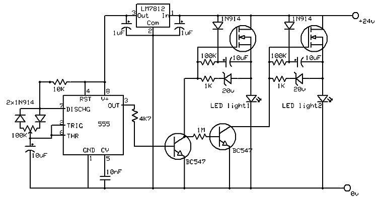 This gives you the option to set the duty cycle of the lights, as shown here. I really need to get out more...... |
||||
| bob.steel Senior Member Joined: 27/02/2020 Location: AustraliaPosts: 188 |
Great Pete , I've got all the versions detailed here working and been playing to get the right light effects . I just don't seem to be able to get something suitable to security. However I am now moving down another road using an Arduino type code and a Dc to Dc converter to get 5 volts .(or a 5 volt regulator) Using probably an ATTiny85 chip and basic breakout board I think can put a cheap effective N channel Mosfet system to power these blue white lights . So developing it up atm I found an Arduino Instructable that gave Police type lights which I have running and driving Mosfets to turn the light on . The appeal is that the program can be infinitely varied to affect each colour and duration. I saw this Instructable and there are quite a few others of a similar ilk. Now this gives a very useful effect to the lights BUT, Using a IRF520 Mosfet C=783pF , Vt=3.6 v , I have its Gate driven by a 5 volt output signal from the Arduino through a voltage divider of 470 Ohms signal side and 10 K on the 28 volt negative .Common ground wire. Atm The light stays permanently on . Reducing the 28 volt supply down to about 8-9 volts brings the signal through and flashes the lights but it is no good to me down there. I'm pretty sure this is the way I want to go now but I don't understand why the Mosfet isn't getting the signal through when the voltage is up higher. Can anyone comment ? Looking into this further the sites I have seen say put the mosfet on the high side even though it is a N channel . So I moved it to the high side but that seems to create a problem . With the positive connections to the lights joined the lights in it work well but they are not at full intensity so I need a way to get the gate voltage to about 10 volts I think? It has a common cathode/negative so putting the two light positive wires together does not seem right . There is a voltage divider / signal set up on each mosfets gate and it seems to allow the mosfets to turn on dependent on each signal pulse,but the white light although flashing seems to be constantly on at a lower power. Anyway here is what it looks like now .Policeflash Edited 2021-07-16 18:19 by bob.steel |
||||
| bob.steel Senior Member Joined: 27/02/2020 Location: AustraliaPosts: 188 |
Great ! Everyone has one to bed it seems . Now I'm not using their schematic. I have two Mosfets with 2 gate drivers common drain and common source but I find the light is flashing both colours each time rather than blue then white . There seems to be leakage from one mosfet to another ? How do I stop that? |
||||
| Warpspeed Guru Joined: 09/08/2007 Location: AustraliaPosts: 4406 |
Hardly surprising Bob. There have been some very good and innovative ideas presented here by several people, all of which you have rejected. Cheers, �Tony. |
||||
| bob.steel Senior Member Joined: 27/02/2020 Location: AustraliaPosts: 188 |
What is it an information offered site or a competition between you three? You response seems to indicate the latter. You all like patting each other on the back too don't you. Even if the circuit does not work . What good is that to anyone asking questions ? I'm looking for suggestions to get something practical that will enhance my security installations . What does it matter which one I pick or don't pick? Come on man ,whatcha talking about? Edited 2021-07-19 15:51 by bob.steel |
||||
| Pete Locke Senior Member Joined: 26/06/2013 Location: New ZealandPosts: 182 |
Bob, your requirement changed through the posts. The main requirement was to high side switch with N-channel MOSFETS. Mike came up with the very clever way of doing that, and we added other control options. Good to see you are approaching the result you are after though. Also, don't forget that when the signal sent to the LED driver is high, it turns them off. If you use a driver transistor with the MOSFET's as shown in the schematics, the full brightness should be realised. Cheers Pete'. Edited 2021-07-19 16:04 by Pete Locke |
||||
| wiseguy Guru Joined: 21/06/2018 Location: AustraliaPosts: 1206 |
Bob lets call a spade a spade, which circuit that had videos posted of it working does not work ? Well it matters in that if you pick one thats proven to work you will be a lot better off I also suggest that you stay with a circuit which has been proven to work and if you wanted it to behave differently keep working with your "helper" until you achieve what you want. Jumping boat to boat everytime you get a hiccup only leads to frustration all round. A couple of posts ago you said to Pete: Were you mistaken or lying or only when you said a few posts later that "Even if the circuit does not work" Lastly if a circuit is clever or unique you are suggesting that we shouldnt be able to say hey that was a cool idea ?? Pats on the back are few and far between here, just cause it happened with one design in your post does not mean its endemic. And no one here is that plastic or shallow that they pat others on the back for an idea that doesnt or wont work - quite the opposite. Not sure why you seem to be a bit angry and insulting to all those that have endeavoured to help, its not the best way to ask for further help - sorry for your frustration but electronics can be just like that at times? If at first you dont succeed, I suggest you avoid sky diving.... Cheers Mike |
||||
| bob.steel Senior Member Joined: 27/02/2020 Location: AustraliaPosts: 188 |
Predictable . The problem is I choose not to use a circuit that turns one light off and another on with little control between times.Changing resistors and capacitors affects the oscillation rate but my needs seem to be better suited to a micro controller with which I am very familiar . Please don't use words like "liar" here. That's not necessary is it. I am developing a light to suit my purposes and it takes whatever time it takes . I have used the circuits given for experimentation getting them going but destroying components in the process. A learning process which includes learning to build boards in Kicad and Eagle . So nothing is lost . Nothing is wasted . All of all of your inputs have been studied and built to develop practically what will suit the final application. All of your inputs are appreciated and the time spent acknowledged and appreciated. I have however moved on. I like the flashing of the Police car circuit and am considering adding a third red LED lamp to the mix when I get the right Mosfets and get them to behave with the cheap lights I intend to use. These lights, when I settle on and build about 20 of them ,will go on shop fronts in Cairns and Atherton where they have a constant problem with theft and vandalism. |
||||
| Solar Mike Guru Joined: 08/02/2015 Location: New ZealandPosts: 1162 |
Bob a cpu will give you ultimate control to achieve exactly what you want and as you say you have learnt some new ideas through your experimentation and input from TBS, building designing any electronics is always a learning experience, and yes sometimes there is smoke... I can understand wanting to use components on hand, however there are some smart mosfets for sale now that allow high side power switching with low side control from a cpu, see this example IR6226 , there are others similar, coupled to your cpu would make the easiest to build solution for high side power switching considering you need quite a number. One of those 8 pin Picaxe chips 08M2 would be ideal for this sort of thing. I quickly drew up this circuit, which is what I would use in a similar case usage where the switching is quite slow and some of the parts are already on hand; the SI8752 chips are used in solid state switches. The circuit would have to be duplicated for each lamp. 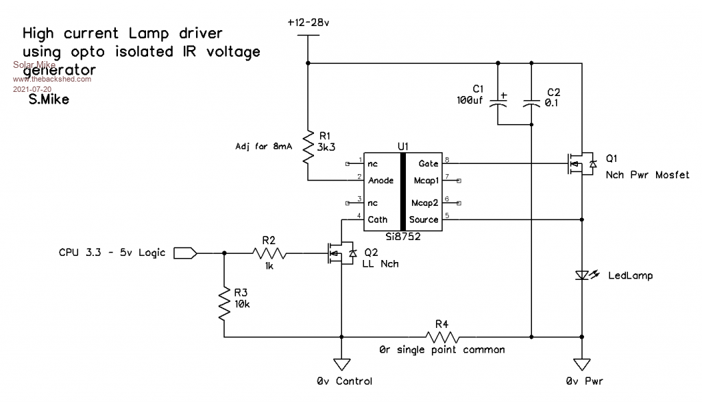 Alternatively Solid State DC Relays that work with DC maybe the quickest solution. Cheers Mike Edited 2021-07-21 08:30 by Solar Mike |
||||
| bob.steel Senior Member Joined: 27/02/2020 Location: AustraliaPosts: 188 |
Thanks Mike Ill follow that through . $5 a relay and 3 needed and a month wait I don't think that's an option for me. Si875x Isolated FET Driver Evaluation Kit, Silicon Labs at USD $60 is just moving ridiculously off target for me . Edited 2021-07-22 15:48 by bob.steel |
||||
| The Back Shed's forum code is written, and hosted, in Australia. | © JAQ Software 2025 |
