
|
|
Forum Index : Electronics : Circuit to flash one LED then the other at about a second each.
| Author | Message | ||||
| Warpspeed Guru Joined: 09/08/2007 Location: AustraliaPosts: 4406 |
A 4069 is no good, its an ordinary hex inverter. MUST be the Schmidt trigger type of inverter, or it will not oscillate. Cheers, �Tony. |
||||
| bob.steel Senior Member Joined: 27/02/2020 Location: AustraliaPosts: 188 |
Got a first draft of this going with a schmidt trigger cd4584 chip I had in the bits box . Runs but one lamp always on and the other flashes so I have to sit down and check it out a bit more. Might have damaged the MOSFETS but I had no electrolytics of that value so used small ceramics so gotta play around with that .Chip could be damaged also.Dunno where it came from. Mikes circuit working but getting full current to the main white light that takes abut half an amp isn't working yet either .Its only getting about 10% of its needed power. Its progress though . Edited 2021-06-21 09:00 by bob.steel |
||||
| Warpspeed Guru Joined: 09/08/2007 Location: AustraliaPosts: 4406 |
O/k Bob. It flashes so the oscillator is running. If one LED is on all the time could be a shorted mosfet or one section of the 4584 chip could be dead. There are six inverters in that chip, try using a different one for the second stage. Cheers, �Tony. |
||||
| bob.steel Senior Member Joined: 27/02/2020 Location: AustraliaPosts: 188 |
Thanks Tony. I've changed the caps and a mosfet and now both lights are flashing . The white a constant 1 second on off but the blue which takes a lot less current flashes 3 or 4 times in that one second giving an effect that I find agreeable. I'm now wondering how I can play with the circuit to achieve different results . I assume the size of the capacitors will affect the rate and more capacitance would mean a longer time? Is there anything else in there Tony that can be tweaked to get the result I am after.? I've still got 3 more inverters too . The MOSFET carrying the white light at about half an amp gets very hot too. Oh should mention I have been varying the voltage and the above results are at 18v odd. At 27v it doesn't oscillate or is doing so fast it cant be distinguished. |
||||
| Warpspeed Guru Joined: 09/08/2007 Location: AustraliaPosts: 4406 |
The 1meg resistor and 1uF capacitor on the first stage set the frequency, and that is really about all that is tweakable. It should work over a pretty wide dc voltage range. I have no idea why there are multiple flashes on one Led only, that is very odd ? Cheers, �Tony. |
||||
| Pete Locke Senior Member Joined: 26/06/2013 Location: New ZealandPosts: 179 |
Sorry, forgot to mention that a second gate is needed as is shown Here for a 4069 to be used as an oscillator. They work well. Also, as the current is fairly low for the LED lights, is there any reason Bob you want to use FET's? A common PNP bipolar transistor easily handle the load and be simpler to put together. Cheers Pete'. |
||||
| bob.steel Senior Member Joined: 27/02/2020 Location: AustraliaPosts: 188 |
Well its about 900 mA at 27 volts but mainly I have a bag of different Mosfets to use up and clearly I will not use them all if I get to be 135. Thanks Ill have a look at the 4069 too Pete. Been looking at that reference . Where might I connect the common cathode lamp to that then? It seems fine for two separate led's but I don't understand if I can connect my lamp in there. Edited 2021-06-21 18:55 by bob.steel |
||||
| Warpspeed Guru Joined: 09/08/2007 Location: AustraliaPosts: 4406 |
Pete is quite right. Many variations are possible. Cheers, �Tony. |
||||
| bob.steel Senior Member Joined: 27/02/2020 Location: AustraliaPosts: 188 |
I just lost my ability to edit posts .Guess that's a hitch with the forum . No its time based I see now. Damn thats a nusiance . I edit my posts often to correct my bad spelling and grammar mistakes. Edited 2021-06-21 19:05 by bob.steel |
||||
| Warpspeed Guru Joined: 09/08/2007 Location: AustraliaPosts: 4406 |
No time limit. You can edit right up until there is a new post after yours. Cheers, �Tony. |
||||
| Pete Locke Senior Member Joined: 26/06/2013 Location: New ZealandPosts: 179 |
Well its about 900 mA at 27 volts but mainly I have a bag of different Mosfets to use up and clearly I will not use them all if I get to be 135. Thanks Ill have a look at the 4069 too Pete. Been looking at that reference . Where might I connect the common cathode lamp to that then? It seems fine for two separate led's but I don't understand if I can connect my lamp in there. Sorry Bob, that link wasn't another option for your setup, it was just to show the change in the oscillator circuit if you went with the CD4069. When time allows (probably this weekend) I'll scratch out a circuit and set it up on a breadboard. Once the final component values are known I'll post it here. It's very simple, and will probably use TIP42 PNP transistors. It'll be an option, but unfortunately not with your life time supply of FET's :-). Although I have an idea that may work with them. Will see how that pans out, but would be a higher component count. Cheers Pete'. |
||||
| Pete Locke Senior Member Joined: 26/06/2013 Location: New ZealandPosts: 179 |
Well, it was a very quiet day at work Friday, so a rummage through the crap I have in the 'Might be useful' draw produced two circuit boards with just about the right bits to try on version of the flashing light. This is the discrete astable driving a high side switching N-Chanel FET. Totally the wrong device, but it was all I had. 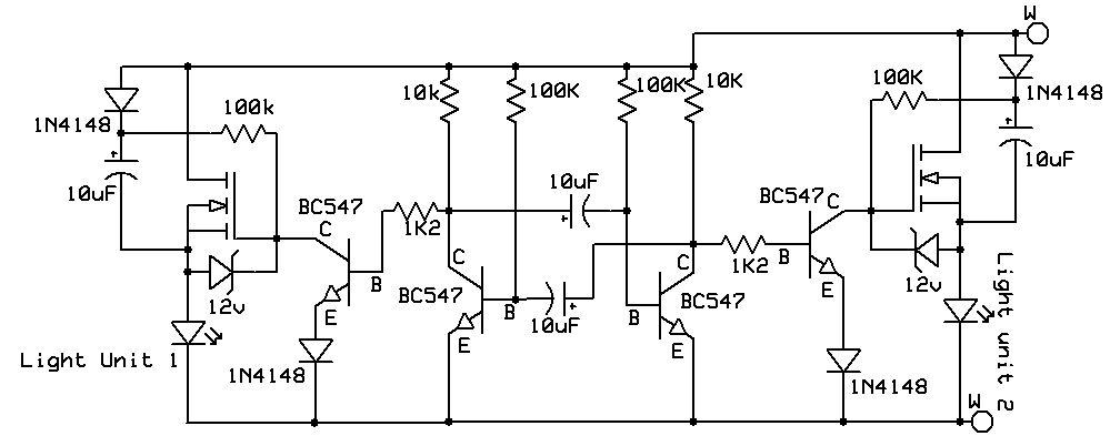 Here it is working, all be it with only one lamp driver attached. The more astute will have noted the polarity of the astable caps are drawn reversed, but they were put together correctly. The FET has an Rds ON of 1.2ohms. Not ideal. The load is a 1amp light, with the FET only getting to, at a guess, 25degC. Saturday here was wet which was perfect shed weather. The next two variants are more practical, especially with the component count. This simple bipolar flasher shows a CE voltage drop of 0.39v with again a 1amp light. 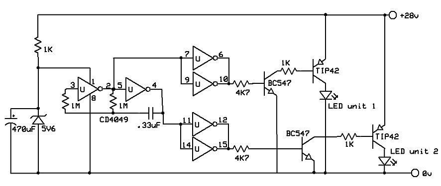 The oscillator was meant to be a CD4069, but the three I have are somewhere safe. They will turn up when I'm looking for something else no doubt  . So the chip is a 4049, which for this purpose is near enough. Here it is merrily doing its thing. . So the chip is a 4049, which for this purpose is near enough. Here it is merrily doing its thing.And the last is what I was aiming for, high side N-chanel switching. Again with a 1amp light. FET's are from a dead UPS, with a 70mOhm Rds ON. Voltage drop across them was .08v with the 1amp load. 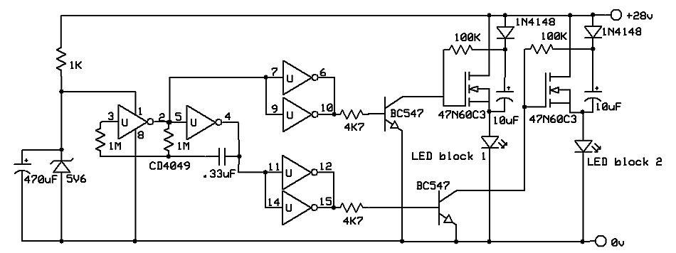 Hope one of these will suit your requirements Bob. Cheers Pete'. This is the proof. Edited 2021-06-26 15:54 by Pete Locke |
||||
| bob.steel Senior Member Joined: 27/02/2020 Location: AustraliaPosts: 188 |
wOw ! Thanks Pete , Heck of a lot of work there . Gonna take me quite a bit to study that and make one up but the video flashing looks very good. Thank you very much mate! |
||||
| bob.steel Senior Member Joined: 27/02/2020 Location: AustraliaPosts: 188 |
I've got the basics of Kicad and now I'm working on Eagle . I pretty well have the basics there too and the library is easier to understand and work with I have found so far . So Ill make up this board for the last one of Pete's circuits and see if I can get some boards made if it runs in breadboard mode for me. Thanks all . Back in a month maybe. |
||||
| bob.steel Senior Member Joined: 27/02/2020 Location: AustraliaPosts: 188 |
Well I had to have a go in Eagle to make Pete's board but I'm not confident that I will have a useable board if I go ahead as it is . Is there anyone there who is proficient in Eagle enough to point out any obvious flaws . ? I've run the two error checks and it seems OK so I'd place the order with just a small assist from someone . Parts well I had to find the CD4049 library and bring it in but other parts were a bit of a punt really . I find it confusing with so many parts and weird names. I don't even know how to get the board and schematic from one person to the other yet but I'll put up the zip file and if more is needed to import it please let me know. LED Flasher_2021-06-28.zip Edited 2021-06-28 19:34 by bob.steel |
||||
| wiseguy Guru Joined: 21/06/2018 Location: AustraliaPosts: 995 |
Hi Bob, sorry to hear that you had troubles getting my circuit to work properly. I attached a decent load to it (also for my peace of mind) & filmed it for you. As Peter demo'd a lamp load to confirm operation of his creations I created 2 videos to confirm/demonstrate that my circuit can also easily drive real loads. The first video is a load ~ 15W (0.7A @ 24V) here1 The second video is a load ~ 45W (1.83A @ 24V)here2 In both cases the FET (BUK455-60) stayed at room temperature - However I am not precious about you building my version and fully support you building which ever design takes your fancy. I havent used Eagle so I'll leave it to others to check your files. Just figured out why the lamps were so bright - I think they were 12V lol. Edited 2021-06-28 22:17 by wiseguy If at first you dont succeed, I suggest you avoid sky diving.... Cheers Mike |
||||
| Warpspeed Guru Joined: 09/08/2007 Location: AustraliaPosts: 4406 |
I have never used Eagle either, so cannot help with that. Cheers, �Tony. |
||||
| bob.steel Senior Member Joined: 27/02/2020 Location: AustraliaPosts: 188 |
No sweat . Yes I saw your videos Mike . I decided to make up Pete's third circuit in Eagle . Didn't have any trouble with it . The circuit seems to work as I need it to do . I just decided ,yes that will do the job especially as the shorting to the Mosfet showed I can connect my LED spotlight there . I decided to go straight to the circuit board and get some made for my first experience of that . I have 3 other circuits now based on warpspeed's and yours that I have been playing with and blowing up often . I got my parts tester today and that's a fascination in itself. Some of my transistors after use in my circuits stop working and then on the tester they just show as resistances so the tester lets me eliminate them and get new ones in so it works again and i can play some more. My system voltage is 54.5v charged and I split off half of the battery bank to run the security lights I'm fashioning my systems on, so the running voltage is around 28 volts on all of them . Well above 24 volts ,so I have to get the higher rated caps . Had one go bang already . Its all fun. Thanks for your help again to all and I'll just wait a while to see if anyone does eagle circuits as a second opinion would help to ensure I'm not wasting my money on boards that don't work properly due to my lack of skills . Edited 2021-06-29 19:54 by bob.steel |
||||
| wiseguy Guru Joined: 21/06/2018 Location: AustraliaPosts: 995 |
The two zeners shown in Petes first schematic should also be included on the third schematic (between the source and gate of the FETs) - I do accept that they appear to be working ok currently with incandescent lamps. Anywhere from 12V - 18V zeners are suitable. The capacitors could get to almost the supply voltage and a lot of FETs are only specd to 20V Max G-S. The zeners also ensure the caps have a good charging path before using their charge to fully turn on the gates. The LED loads will probably behave very differently to the incandescent loads (if zeners are not fitted) as the incandescent lamps actually help to charge the electrolytic capacitors due to their low resistance nature. Edited 2021-06-30 00:34 by wiseguy If at first you dont succeed, I suggest you avoid sky diving.... Cheers Mike |
||||
| phil99 Guru Joined: 11/02/2018 Location: AustraliaPosts: 1785 |
The non linear nature of the LEDs can be overcome by putting a resistor in parallel with each. Try 2.2k 0.5W or 1k 1W. |
||||
