
|
|
Forum Index : Electronics : Time for a new Warpinverter build - #2
| Page 1 of 5 |
|||||
| Author | Message | ||||
| rogerdw Guru Joined: 22/10/2019 Location: AustraliaPosts: 955 |
My apologies for being AWOL for so long. I was going to carry on the original thread ... but thought it may be clearer if I just start a new thread. Original thread here ... The original project started about a year ago ... and I wound the secondaries on the three smaller transformers ... but then it all stalled. I stalled! I finally got back onto increasing the size of the core for the main toroid. I had built a core winding device before I started winding the other toroids but never got to use it. Our ride-on mower wore out the main spindles bearings and it was as cheap to replace the whole assemblies rather than just the bearings ... so I repurposed them for this job. Even used the old blades. I used 3kW Aerosharp cores and removed 20mm from the ID (now 120mm), then wound additional turns until they reached 250mm OD. The finished size is 120mm ID, 250mm OD and 71mm high ... x2 Combined they weigh 39kg. The originals are spot welded at each end, so I also built a spot welder to do the same. The first one was from a microwave oven transformer, but wasn't powerful enough ... so I bought a cheap s/h welder and rewound the transformer secondary and fitted a timer/power and foot control from ebay. Works well enough. I used some epoxy resin to glue the finished cores together and cut and shut some 150mm drain pipe down to 120mm to insulate the inside of the core ... and added some plywood plates top and bottom. If you were following at any stage, you may remember I was going to add 5mm spacing between the core and the winding to try and reduce any capacitive coupling, hence the thicker material on the core ... under Warpspeed's guidance. 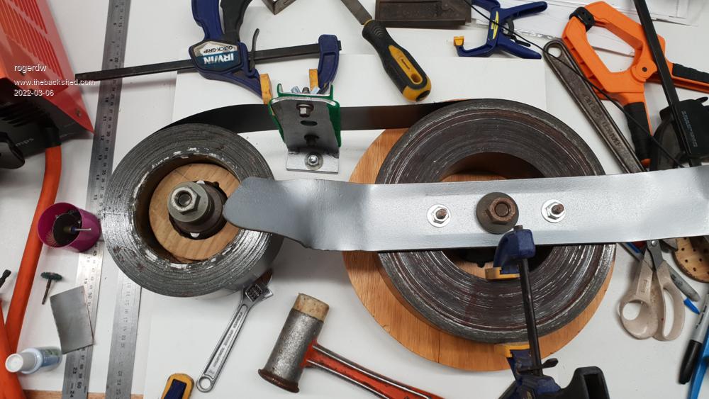 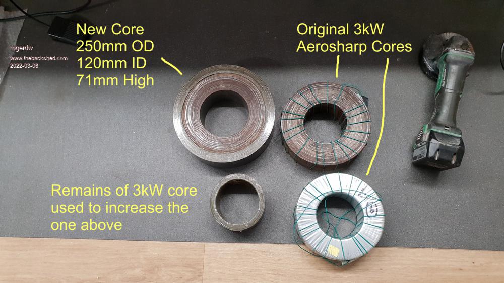 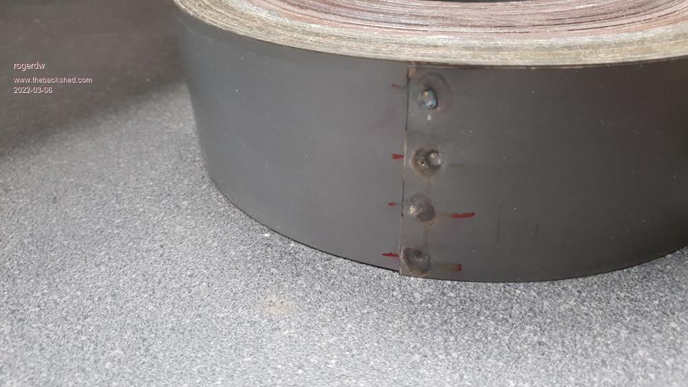 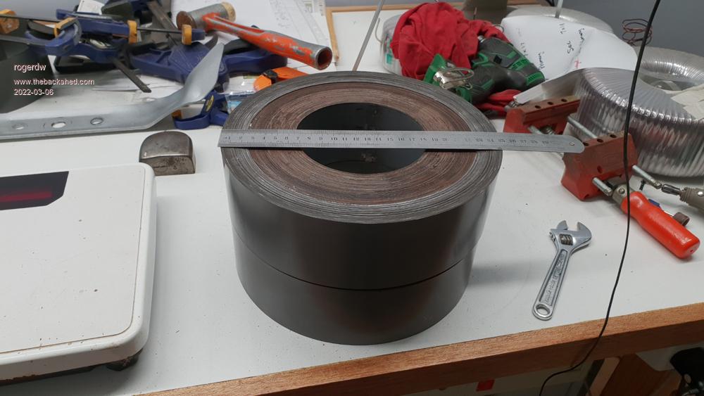 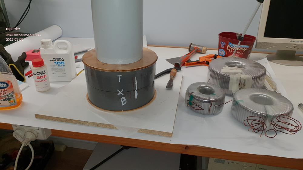 The 3 toroids on the right are the ones to be used with the biggie. They have the first winding on and still require their thick windings to be added. The 150mm pipe is resting on top with a heavy weight above ... to compress it while the epoxy goes off. Cheers, Roger |
||||
| Murphy's friend Guru Joined: 04/10/2019 Location: AustraliaPosts: 678 |
Very impressive, you'll have fun winding that monster  Any chance of a picture of your spot welder? Any chance of a picture of your spot welder? |
||||
| rogerdw Guru Joined: 22/10/2019 Location: AustraliaPosts: 955 |
Thanks Klaus, I keep telling myself I can do it.  I don't recall if I took any photos inside the welder, I'll see what I can find. Here's one of the finished product. The display and the two pots are from the ebay controller I added in. Very handy for getting consistant results with timing and power levels. The welder terminals are only brass bolts at this stage ... but if I get the settings right, and the pressure ... it works great. If I get too much current through it, the transformer metal burns straight through and welds to the end of the bolt ... and I need to grind it off back to clean brass to get a good weld again. I also added a foot control so I could use both hands to hold everything together, then weld. Here's what the ebay spot welder controller looks like ... 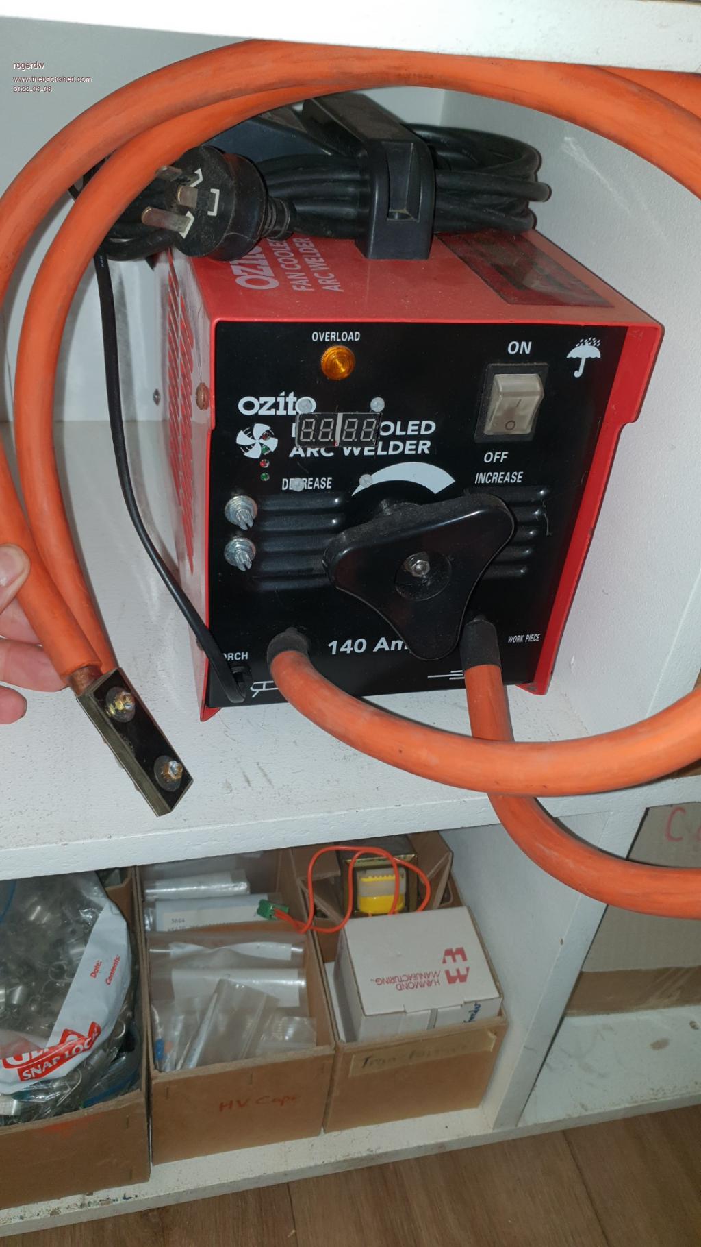 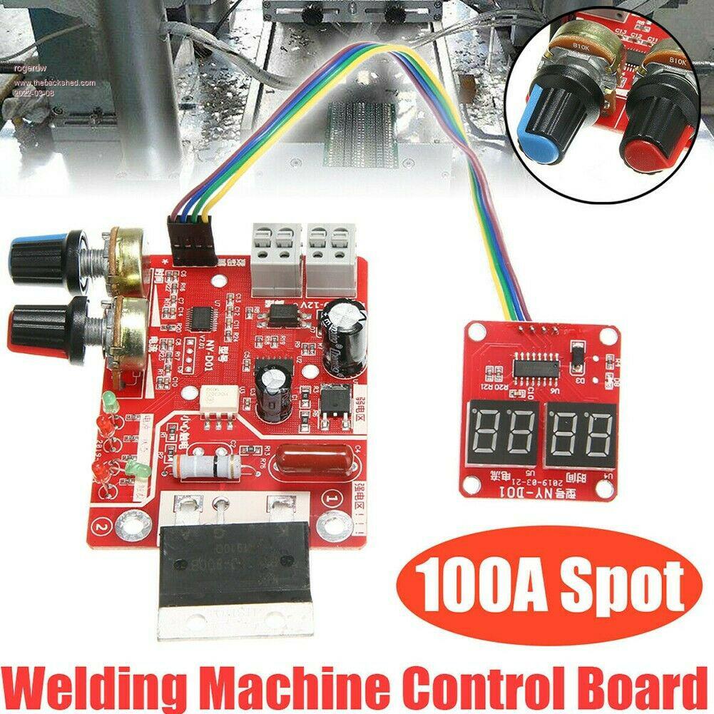 Cheers, Roger |
||||
Haxby Guru Joined: 07/07/2008 Location: AustraliaPosts: 426 |
Looking good Roger! I'm taking a break from my projects too, but still lurking in the background! |
||||
| rogerdw Guru Joined: 22/10/2019 Location: AustraliaPosts: 955 |
Thanks Phil, glad to see you're still around. Did you end up getting to use any old aerosharp IGBT modules in your projects. I did see your driver boards ... they look really good. Cheers, Roger |
||||
| Murphy's friend Guru Joined: 04/10/2019 Location: AustraliaPosts: 678 |
Thanks Roger, I did not know that only 100A can spotweld that big core lamination. Last time I used a spot welder was about 60 years ago, that thing used water cooled copper electrodes and I'm sure many hundreds of Amps. When I moved a few turns of lamination from the inside to the outside to make the holes of two cores equal size I just epoxied them in place. You took that process to another level altogether  . .That welding machine control board looks interesting, I have an old stick arc welder, capable of 125A, might be useful for a spot weld project. You will find that a good set of biceps helps when you have to move that heavy core as you wind on turns  . No need for gym exercises until its finished . No need for gym exercises until its finished  . .PS, just looked at your top picture again, you welded between the two bolts on the *surface*. Always thought spotwelding is done *between* two sheets of steel by an electrode on each side. It did not occur to me it would work on the surface of one sheet alone and still weld through to the layer below. Thanks for enlightening me. |
||||
Chopperp Guru Joined: 03/01/2018 Location: AustraliaPosts: 1126 |
The latest Silicon Chip has a Capacitor Discharge Welder project for welding tabs to batteries etc using this method. Interesting project My only experience with spot welders was a big unit which did the welding between two sheets of metal. Brian ChopperP |
||||
| rogerdw Guru Joined: 22/10/2019 Location: AustraliaPosts: 955 |
The device switches the primary winding of the welder at 240v, though I have no idea what the actual currents are. I haven't fitted it to a heatsink or anything, so I probably need to check the temp if I do any long jobs. I did think of that originally, and in hindsight it would have been so much quicker and easier. Though I've always wanted a spot welder ... I just need to buy some decent electrodes. Yeah, I've gone to shift it a few times already and really had to brace myself. Several times it stuck to the board and took a bit of seperating. I'm not sure how I worked it out ... but at some stage I realised the core is a very long strip ... and with the oxide coating they use, the current would have had to flow around and around all the way to the other end. I doubt the welder would have had enough oomph to do that. As it was, I didn't get anywhere until I used my dremel to polish back to bare metal, both sides of the end bit, and the places it had to weld to on the next layer. Then it just required the right pressure and timing to make it stick. While the sacrificial cores I used to add to my main core were actually in a single continuous strip ... the main cores I added to were made up of hundreds of short lengths ... all around 18-24". If I was using those to build up a core, it would have been impossible to keep it tight and build it up fully. They were all from 3kW Aerosharps ... but they were from two different manufacturers. 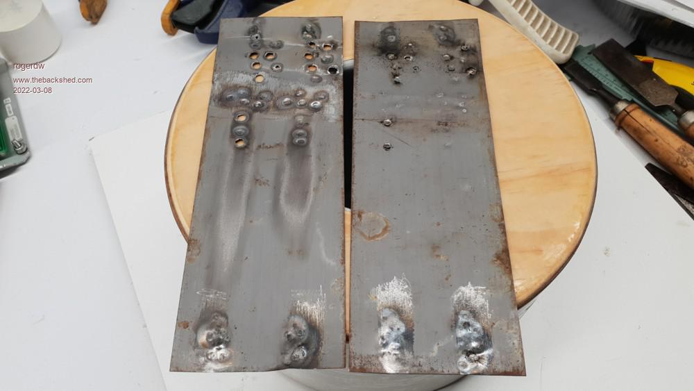 Pretty messy and was easy to just burn a hole through if it didn't press through to the second strip, which I guess halves the current through each strip. Certainly would be a lot easier if I had some means to apply a consistant pressure. Anyway, it's all done now and hopefully with all the superglue I poured over it after I finished ... and the epoxy resin I used between the two, it will not come loose and rattle its brains out for the next 20 years.  Cheers, Roger |
||||
| rogerdw Guru Joined: 22/10/2019 Location: AustraliaPosts: 955 |
Yes I saw that too, though haven't read the article yet. Could have saved me a lot of effort if that would work. I have also wondered if I had been cleaning back to bare metal properly from the beginning, whether my first modified microwave oven tx based one might have done the job. It didn't matter how much power I used ... if it wasn't squeaky clean it simply would not burn through the oxide layers to melt itself together. Cheers, Roger |
||||
| Haxby Guru Joined: 07/07/2008 Location: AustraliaPosts: 426 |
I haven't tested my board on the aerosharp igbt boards, but I have been doing a bit of work on other parts of the project. It was an effort to get it going, but I was able to get some software and hardware going to be able to monitor, control and most importantly reset the ECU of the Prius. The latter is most important because should there be an overload on the Prius battery, the ECU throws an error code and shuts down the vehicle till it is reset. That's something that would cost thousands to do by a Toyota technician and the car would have to be towed to the garage. I also worked on a pre-charge circuit between the Prius battery and the inverter. Originally I was going to use the built in Prius precharge system, but because I don't have direct control of it, and a few other reasons, I decided to have a dedicated precharge circuit for my inverter. I will update my build thread soon! |
||||
| rogerdw Guru Joined: 22/10/2019 Location: AustraliaPosts: 955 |
Sounds like a monumental task working all that out, well done. I don't know much about them at all but did watch a lot of videos a couple years ago by that teacher/lecturer who dismantles and reassembles them on video. Fascinating stuff. Cheers, Roger |
||||
| rogerdw Guru Joined: 22/10/2019 Location: AustraliaPosts: 955 |
I've very slowly been working at this large toroid. From my experience with the first 3 toroids and realising the importance of making the first layer as accurate as possible ... I decided to groove the core on all inner and outer edges ... to locate the windings accurately. The epoxied plywood top and bottom 'washers' are 7mm thick and the inner pvc insulation is 6mm thick ... so some grooves around the edges should not cause any insulation issues. The thick insulation is an attempt to keep capacitive issues from causing spikes in the secondary as per Warp's suggestion after early builds by others. I settled on 112 turns per winding, so spread them out to fit almost one full layer ... 15mm gap between the ends. I started by using a small round file but progressed to using a hacksaw to cut a small groove ... then cleaned it up with the file. 450 slots later!!! The first winding went on pretty well and then two layers of mylar tape. The third photo is after the 2nd winding and a start for the mylar wrapping. I am interested in opinions as to whether I should do two full layers of mylar between windings ... or would one suffice. I am using new wire for this big toroid ... 1.8mm. I can see I'm going to run out of mylar before I'm finished the seven layers ... so I need to order more. 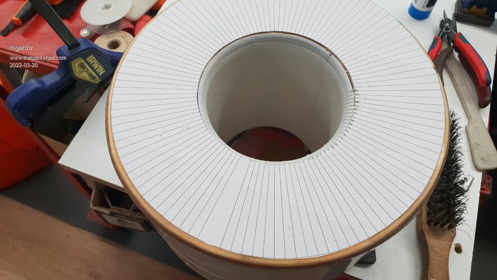 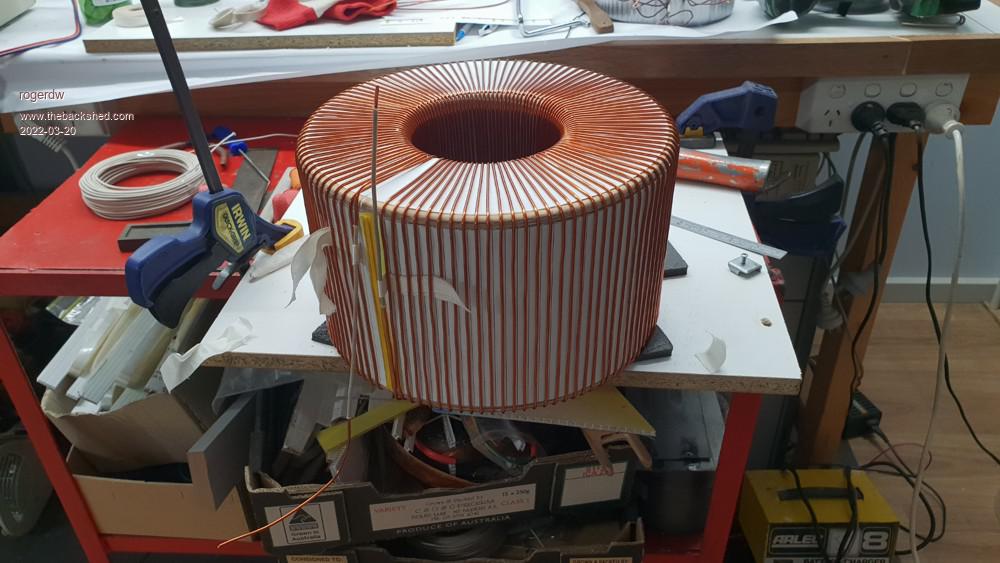 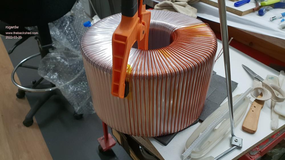 Cheers, Roger |
||||
| Murphy's friend Guru Joined: 04/10/2019 Location: AustraliaPosts: 678 |
I see you a sucker for punishment Roger but, oh boy, you do turn out a very neat job. Re your Mylar question I would not bother insulating each layer. With your neat style of winding the second layer turns fall between the earlier layer anyway. Too much mylar eats up hole space. I was never convinced about Tony's capacitive coupling to core theory. To my understanding, a capacitor has two 'poles', each being connected to the power source. The core is connected to nothing! So I'm very curious if you have startup mosfet failures as I had, which I tamed with big chokes and a slow starting procedure. That new wire must have cost you a penny . |
||||
| rogerdw Guru Joined: 22/10/2019 Location: AustraliaPosts: 955 |
Thanks for the kind words and yes I am a sucker for punishment ... though I've come this far, I need to complete the job some how. Interesting that you should say that ... if I hadn't used mylar after the first layer, I would have fitted the second layer wire between the winding of the first layer ... but the mylar covered over those gaps. I'll finish off the layer over the second winding, then keep going and decide after that. I don't know enough to argue the case either way, though the waveforms Andrew showed and the discussion around them sounded feasible enough. In fact, the reason I held off starting early on was because I was waiting for Mark to try out the transformer he wound with extra space between the core and the windings ... but I don't think he ever got around to trying it in the end. I honestly don't recall just how much it cost, it's been sitting in its box on the shelf for the last year or more waiting for me to use it. It was 7kg and I originally bought it to build a pwm inverter ... but after reading and reading and procrastinating, decided to build a Warpverter instead. I am very happy that I was able to use second hand wire on all the other toroids and am fairly confident it would have worked on the is one as well. Cheers, Roger |
||||
| Godoh Guru Joined: 26/09/2020 Location: AustraliaPosts: 664 |
I go along with Murpy's friend on the mylar issue. You are doing an incredibly neat job Roger, as you have plenty of time it is a good practice, it may make the life of the transformer longer but insulating each layer is not really necessary. There would only be a couple of volts between each turn on alternate layers. Electric motors are wound with random wound coils that are placed in slots, there is only the enamel there to insulate them. Some fail over time from vibration damage to the enamel if they are not varnished enough but most fail from overload, moisture and dust ingress. It is great to read and see the photos of your build Pete |
||||
| rogerdw Guru Joined: 22/10/2019 Location: AustraliaPosts: 955 |
Thanks for the compliment Pete and your thoughts on the mylar ... it does make sense. When you say it like that it makes a lot of sense. I'm hoping I can finish all of the windings each in their own one layer ... that way it does keep the potential difference between adjacent wires very low ... and the environment should be much kinder than a lot of electric motors ... so I'd have to be very unlucky to have any problems. Cheers, Roger |
||||
| rogerdw Guru Joined: 22/10/2019 Location: AustraliaPosts: 955 |
I've completed five layers of my secondary winding for the big toroid and have run out of wire. Probably enough to do another 50 turns ... but need two lots of 112. The last layer went on really well with the spacing and the wire virtually just falling into place. The previous layer I must have started off wrong and I had to fight it all the way ... but this one was spot on. A little bit of care with the start makes such a difference. I originally bought 7kg of 1.8mm to build an Ozinverter and when I changed plans to build a Warpverter, figured there'd be plenty of wire for the big one. With two layers still to go, I'm tossing up if I buy some more new wire ... or just straighten out some of the 1.7mm from the toroids I've unwound. All the other toroids are wound with secondhand wire. It's certainly getting heavy ... 39kg core and now at least 6.5kg of wire so far!!! 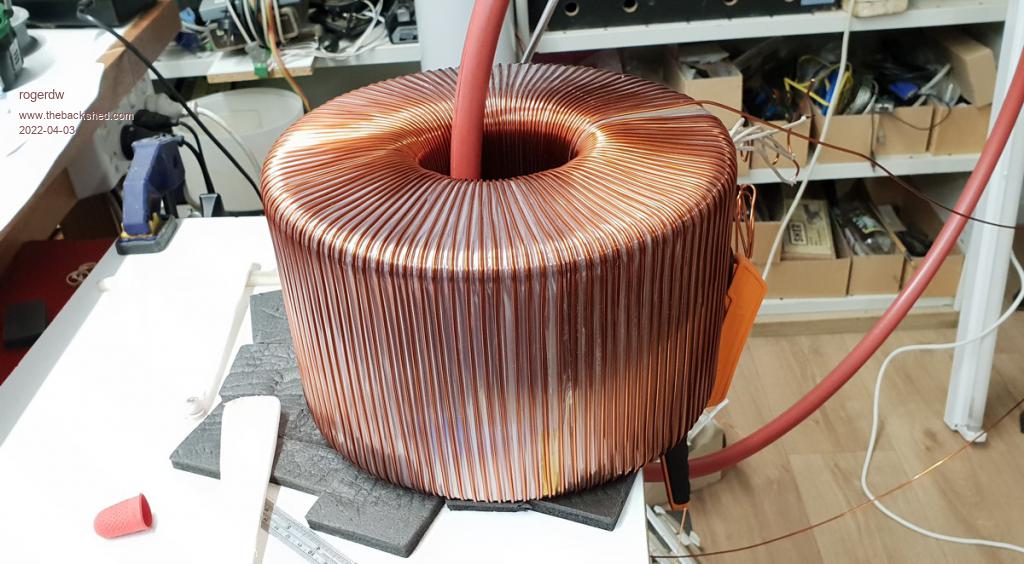 Cheers, Roger |
||||
| Haxby Guru Joined: 07/07/2008 Location: AustraliaPosts: 426 |
Gorgeous! |
||||
| rogerdw Guru Joined: 22/10/2019 Location: AustraliaPosts: 955 |
Haha, thanks Phil. I know it's taking forever to make any progress but I thought I should add some photos. It doesn't really look like it but the bottom one in the stack of three is actually a 3kW Aerosharp toroid ... and the BIG beast is made up of two of those 3kW cores but with an extra 2 inches of added core diameter. I had removed material from the centres to take them from 100mm to a 120mm hole. I stopped at 6 layers of 112T using 1.8mm wire, so should be good for a 60A secondary. Each layer was reducing the hole diameter by 5mm, so I would have run out of room if I continued. I spaced out the wire so that the 112T filled a full layer minus 15mm ... and was really happy that each subsequent layer fitted without closing up that gap. Would have got messy if I'd had to overlap to second layers to get my 112T in. The numbers don't lie (I hope) ... so I should still be able to fit my required primary windings ... as long as I can get or bundle up the appropriate sized wire I need for it. 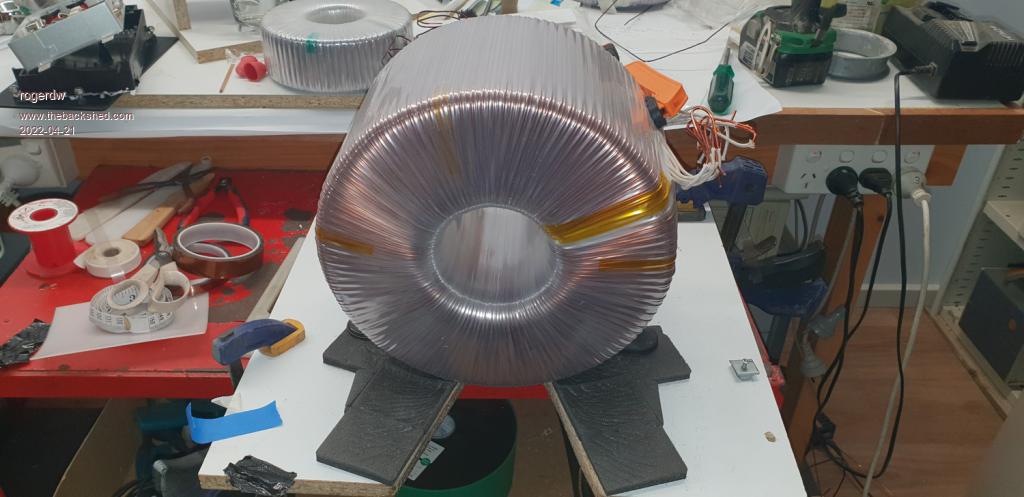 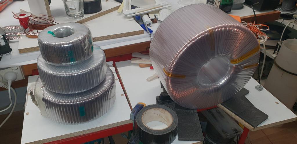 Cheers, Roger |
||||
| rogerdw Guru Joined: 22/10/2019 Location: AustraliaPosts: 955 |
I'm still working away on this project ... just sorting out pcb's for the electronics. I will have my rows of fets screwed down on aluminium plates, which in turn will be screwed to a heatsink with heat sink compound applied. Because the fets need to be isolated, I need to find suitable thermal and insulating material to put between them and the aluminium. In looking online, I see that the (supposedly) better spec material is a horrendous price. I saw some as much as $800+ for a six inch square ... all the way down to $20. My question is just how good a quality is required ... and what is the best value for money. I need 10 pieces 100mm x 25mm. Any recommendations please? Cheers, Roger |
||||
| Page 1 of 5 |
|||||
| The Back Shed's forum code is written, and hosted, in Australia. | © JAQ Software 2026 |
