
|
|
Forum Index : Electronics : Time for a new Warpinverter build - #2
| Author | Message | ||||
| Solar Mike Guru Joined: 08/02/2015 Location: New ZealandPosts: 1125 |
Sil-Pad Roll I use this a lot, maybe ok for what you want and not overly expensive. Cheers Mike |
||||
| InPhase Senior Member Joined: 15/12/2020 Location: United StatesPosts: 178 |
Kapton tape works pretty good. I know, I know... It has high thermal resistance. But it is ultra thin, so you actually come out OK. Pretty cheap and useful for lots of stuff too. |
||||
| Murphy's friend Guru Joined: 04/10/2019 Location: AustraliaPosts: 584 |
I have that Sil pad material mentioned above but then cutting it to size & punching the screw hole for 40x HY4008's looked like too much work. So I got the ready size mica insulators from Altronics, they are doing the job and have not given any trouble. Not expensive either. I also tried the grey flexible insulators but found they could be less than OK with their insulation properties. |
||||
| rogerdw Guru Joined: 22/10/2019 Location: AustraliaPosts: 803 |
Thanks Mike, I started researching the stuff and then got frightened off by the prices from the big 4 mainstream suppliers. Knowing that you are happy with this gives me confidence to use it and not worry about the high spec stuff. Looking at datasheets I see that 'Thermal Conductivity' (along with breakdown voltage) are the main measurements ... in W/m-k ... and this one is 1.6 W/m-k. A 9" square of 3.6W/m-k material is $66 from element14 ... through to really high numbers at 10x the price (RS and DigiKey etc) I had read of people using it but not sure of its performance long term. Do you use silicone grease with it? I plan on using pieces 100mm x 85mm under 12 fets, so not so much cutting ... but still plenty of holes. Trying to keep 40+ insulators lined up all nice and square seemed like too big a task to me ... slap down one sheet and the jobs done. I've never built an inverter before so I have no idea how much heat I have to get rid of. I just didn't want to compromise it by scrimping on the insulators. At this stage I reckon I'll order a roll and see how it goes. Thanks for the suggestions. Cheers, Roger |
||||
| Murphy's friend Guru Joined: 04/10/2019 Location: AustraliaPosts: 584 |
Well, I built quite a few inverters (#6 now in progress) and I never had a heat problem with mine. Rule # 1: make the heat sink an adequate size, the ones you see on those Chinese inverters are way undersized IMO. Lining up 40 mica washers seems tricky if you look at the total figure but is only 4 at a time the way I design my power boards. They are held in place with heat sink compound so no problems with lining up. Beware with your planned method of using a sheet for 12 fets, those holes *have* to be very accurately punched or you get creasing of the sheet. This seems to me more problematic than lining up individual washers. Whatever you do, make it an easy job to replace those mosfets - I speak from experience here  |
||||
| rogerdw Guru Joined: 22/10/2019 Location: AustraliaPosts: 803 |
Thanks Klaus, I didn't realise that it would crease up so easily. I'll either have to use individual ones or be really careful lining up the holes. Although thinking about it, I'll probably make a drilling template for the heatsink, so I could also clamp some of this material between the template and a block of wood to make it accurate. I also didn't realise you still use heatsink compound with this material ... is it only those grey pads that are supposed to be used without? I'm not planning on making six inverters �... �but I'd like to finish at least one before I die of old age. I'd better get a hurry up. �  Edited 2022-05-23 17:51 by rogerdw Cheers, Roger |
||||
| Solar Mike Guru Joined: 08/02/2015 Location: New ZealandPosts: 1125 |
I use the thinnest smear of HS compound with the Sil-Pad material or none at all if the heatsink is really flat. Don't drill holes in it, I use the point of a metal scriber to push a hole through the material via the mosfet in place, then screw in the bolt to tapped thread in HS. Cheers Mike |
||||
| rogerdw Guru Joined: 22/10/2019 Location: AustraliaPosts: 803 |
That's very helpful thanks Mike, I'll do that. Cheers, Roger |
||||
| Murphy's friend Guru Joined: 04/10/2019 Location: AustraliaPosts: 584 |
I use heat sink compound to 'stick' the mica washers in place. Its a very thin smear and most squeezes out with the high clamping pressure I use. For that reason I would recommend to use M3 ss socket head screws and get a T-bar driver for them. Get a few spare M3 taps as well... , and find out how to use alumn to remove broken ones .You may be not building six inverters but you are building essentially four individual ones at the power side and one control board driving them. Give it some real thought how you arrange this, everything on a single PCB like the single transformer inverters is, perhaps, not a good idea beside being expensive due the size & 2oz copper required for that. Have a good look how I built mine, its, perhaps, the most economical use of the heatsink (suggest 2 x full size Aerosharp type) and certainly easier with PCB layout plus just 1oz board material. Those boards are half bridges, much easier to arrange the high current tracks. |
||||
| rogerdw Guru Joined: 22/10/2019 Location: AustraliaPosts: 803 |
Tell me more about using alumn to remove broken taps. Though after chatting with wiseguy, I'm inclined to use his suggestion of drilling slightly undersized holes and forcing nuts in from behind. Then there's less drama involved hopefully. Yes, that is true, I'll be up to #4 with my first one. As far as giving it some thought, that's about all I've done for a couple years ... too much thinking and not enough action, though it's slowly coming together. My plan is to use modules ... with full bridge modules for the smaller three tx's and two half bridge modules for the big one. I also plan to use copper bar soldered to the board for the major busses and extending as connections for dc and the tx primaries. For my first attempt I will probably order 2 oz copper ... but probably more for in case of having to rework the board with multiple mosfets if it doesn't all go to plan. Pcb design is new to me, so that part is taking a while ... but nearly ready to send off my files. Cheers, Roger |
||||
| Murphy's friend Guru Joined: 04/10/2019 Location: AustraliaPosts: 584 |
A few more tips Roger. Google broken tap removal from alumunium and you'll find the alum method. The other method is spark discharge but that needs equipment. Both are *very* slow. Try to minimise blind holes for tapping by locating them between the fins. I do have blind holes at the heat sink edges but they are M4 or M5. If you are not full bottle about tapping heat sinks, it was discussed here some time ago or I can give you a rehash. Drilling templates, I never bother unless I need a dozen or more identical parts. Mark it accurately, center punch it accurately, drill a pilot hole for bigger holes and you get an accurate result. Tap drill size: M3=2.5mm, M4= 3.3mm, M5=4.1mm, M6=5mm You'll find using nuts between the heatsink fins is an exercise in frustration. You could use self tapping screws if you like things a bit agricultural. Would not recommend it for mosfet mounting. I use half bridge modules for all 4 tx's. There are two half bridges, side by side, on each PCB, these can be linked to drive more mosfets. So I have 6 identical half bridge power boards, 8 identical half bridge driver boards and 20 small (2 mosfet) carrier boards. All are 1oz copper. Think about soldering copper bar to the PCB. This requires a *lot* of heat, possibly ruining the board. Better to tin the bar and bolt it on. I use alu bar bolted on, cheaper and works just as well without having to 'tin' it. New to PCB design? Well, there are many pitfalls . Suggest you send the simplest Gerber file first and learn from the mistakes that everybody makes too. These become fewer as you progress but never seem to go away  . . |
||||
| rogerdw Guru Joined: 22/10/2019 Location: AustraliaPosts: 803 |
Not gunna look at the MDM process otherwise I'll get side tracked building one of them.  I know I've read it before but a refresher is a good idea. I had remembered the points of making sure holes are designed between fins ... and to drill all the way through so can make it easier to tap. I do need some holes in the side of the heatsink but they can be 5 or 6mm ... and if I did have any issues I could try another alongside. I have 5 plates plus a spare or two that need 16 holes each ... so I reckon a template done once will still be worthwhile. Thanks for the tap drill sizes, that will be handy. Agreed, they both sound like a bad idea. I do recall reading somewhere on the forum where someone was drilling the mosfets out to handle a 4mm screw. Not something I would do in a hurry, but can understand why they might resort to that. I haven't tried it before so I may well end up regretting the idea. I do have a largish solder pot, so the idea was to set up the board in a rough holder to locate it and the copper bar ... then tin the bar in the pot and transfer it across onto the board. If I tin and preheat the board first, hopefully there will be enough heat in the tinned copper for the two to bond together ... or quickly add a little more heat via the desoldering air gun. Dunno, will need to experiment first. If all else fails, I might need to add bolts. Fortunately I have someone who's been casting an eye over my efforts pointing out my errors and giving me some clues ... so I have a much better chance than without the help. I gotta stay positive or I'll give up. I did go through some of your posts to find pictures of your builds and found pictures I hadn't seen before ... very inspirational. Anyone else who hasn't seen them try here here and here Cheers, Roger |
||||
| Murphy's friend Guru Joined: 04/10/2019 Location: AustraliaPosts: 584 |
Nah, don't give up Roger, you are too deep in it already .The last link above (at the bottom) is what my warpinverter looks like inside, note the way the mosfets mount for easy exchange - I did find that feature very handy later .I used terminal blocks initially, as seen on some earlier pics. Not a good idea in the end, as the terminal does not survive a blow up very well. With building 4 inverters in one box it helps to have a compact, easily serviceable design. One chap here tried to fit his in a full size locker , never heard how that went.I'll take some pics of my tapping stuff tomorrow. |
||||
| rogerdw Guru Joined: 22/10/2019 Location: AustraliaPosts: 803 |
Thanks for the encouragement Klaus, I am in too deep to give up ... so need to stay accountable. I've had the layout of my device in my head for ages ... but the final packaging I'm not too sure of yet. I do like the way you've set yours up ... especially the inter-changeability ... but as you say, when you have to work on them, they are very heavy to lift off the floor. But hanging mine on the wall will be a major task too ... so have to think that through a bit more. Actually it's not just the weight to lift ... it's the strength of any wall to hold it long term without tearing itself off if it hums a bit and vibration rattles things loose. I do have a spot in mind for it all ... under the stairs adjacent my workshop ... and I have considered using decent sized threaded rod to hang it from the stair frame, rather than on the wall itself ... but still undecided. The stair frame is about 300 x 70mm C-section ... so I'm pretty sure that'd be strong enough. With the pcb's I plan to use I'll definitely be soldering the fets on, though they wont be too hard to replace or swap out if I have trouble (I hope). After all my years fixing stuff for a living and complaining about equip that's hard to repair, there's no way I could build something that was going to be difficult to work on and repair. We'll see if my ideas work or not eventually. I reckon Mark was the one building a warpverter into a cabinet ... it looked good from what I saw on his photos. I wonder if he finished it too. Cheers, Roger |
||||
| brucedownunder2 Guru Joined: 14/09/2005 Location: AustraliaPosts: 1548 |
HI Roger. Thanks for any help you have assisted us "Fiddlers" with for a start. I built my compact inverter with the coil I had made years ago. I built it with the idea of using the available space I had available in an Ericsson charger cabinet ,off the scrap heap years ago. The main control panel shelf is mounted on two end angle rails that support and allow it to be slid out thefrontof the case ,I found this to be perfect for service and modifying cabling etc. So, don't give up ,my friend, it's a good hobby and we appreciate good ideas through DIY'ers builds. My thanks also go to my mate, Aaron , a forum expert in solving my problems. I'm more apprective of friendship now as my cancer has caused me to surrender my drivers licence. I never thought how valvuable driving mean't. (I supper from fatigue through kidney failure, causing "Micro Sleeps".) 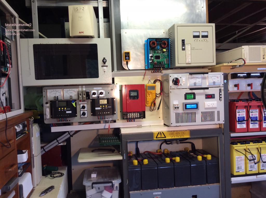 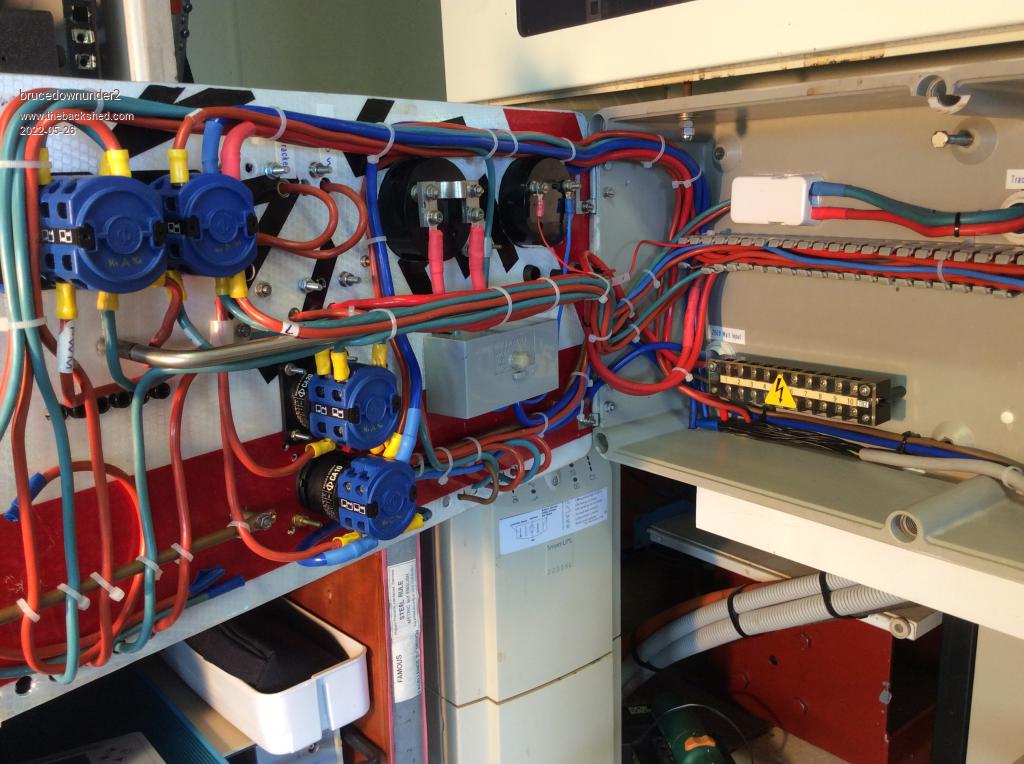 Bushboy |
||||
| Murphy's friend Guru Joined: 04/10/2019 Location: AustraliaPosts: 584 |
Roger, if you take my advise, forget hanging this thing on the wall. Mine weighs 150kg and I very much doubt that yours will be lighter with that monster big Tx. My cabinet is on castors, easy to wheel about. To work on it I use a 1 ton chain hoist to lift it onto a mobile work table. You'll be mounting parts in and take them out until; everything has found its final place in the cabinet and doing that on the floor would be no fun at all. The only ready made cabinet big enough that I can think of would be one of those alu genny boxes as seen on caravan A frames. But with only one door, tricky to work at what's inside. Its not hard to make your own cabinet Mine uses the Aerosharp lid for top & bottom, a 25mm angle iron frame fits on the bottom lid, this frame is smaller than the lid insides so the 4 side panels can slot in. Taking the top of gets me access to the control board, the side panels come off as required to access anything inside or even lift the whole heat sink assembly out to work on it. |
||||
| Murphy's friend Guru Joined: 04/10/2019 Location: AustraliaPosts: 584 |
As mentioned above, here are some tips about tapping holes in a heat sink. Its best to use a tap exclusively used for aluminium. If it previously tapped steel or worse, stainless steel, its no longer sharp enough and jams much easier, risking breakage. Marking & drilling the hole precisely is very important as often the part fitting (PCB, Mosfet) has to line up. My PCB's are laid out on a 100 thou grid so I use a ruler with 20 thou markings - not metric! First I use a clutch pencil to draw crossed lines where the hole has to be. Then I use a scriber to pin prick the exact center. After this a center punch aligns easier with the pin prick mark. I prefer those 'automatic' center punches as they only need one hand but the old fashioned one also works as long as the point is sharp. 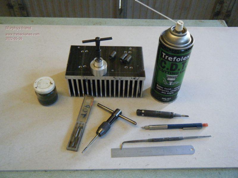 The picture shows what I use. The tap needs to be lubricated, for aluminium kero is recommended but I advise NOT to use that in blind holes. The reason being the kero washes the swarf down the hole and when the tap tip gets there it jams. So I use Trefolex with blind holes. The swarf sticks in the grooves then. The little jar in the pic holds kero. The tap wrenches shown are IMO better than the ones that usually come in a tap set as the shorter handles restrict the torque and reduce breakage. In my experience a tap in aluminium most likely breaks when it is backed out so, if it jams, be patient and turn the wrench slightly back and forth until its free enough to remove. For blind holes it may be better to use the tap set with 2 or 3 taps, applied in sequence. For thru holes less than 6mm deep the taper tap is my preference. The tap guide shown is well worth while to have (mine was made from an old floor mounted door stop), it has inserts for different size tap shank diameters. That tool guarantees a straight tapped thread .For deeper threads I turn the wrench 2 or 3 times and then back it out completely to remove the swarf stuck in the grooves. Repeat until tapping is complete. This sounds slow and tedious but boiling out a broken tap is 1000 times slower and ruins your whole day. And its often not possible to drill and tap another hole next to the broken tap if something that cannot be changed fits there. So, patience is the word when it comes to drilling & tapping heat sinks. 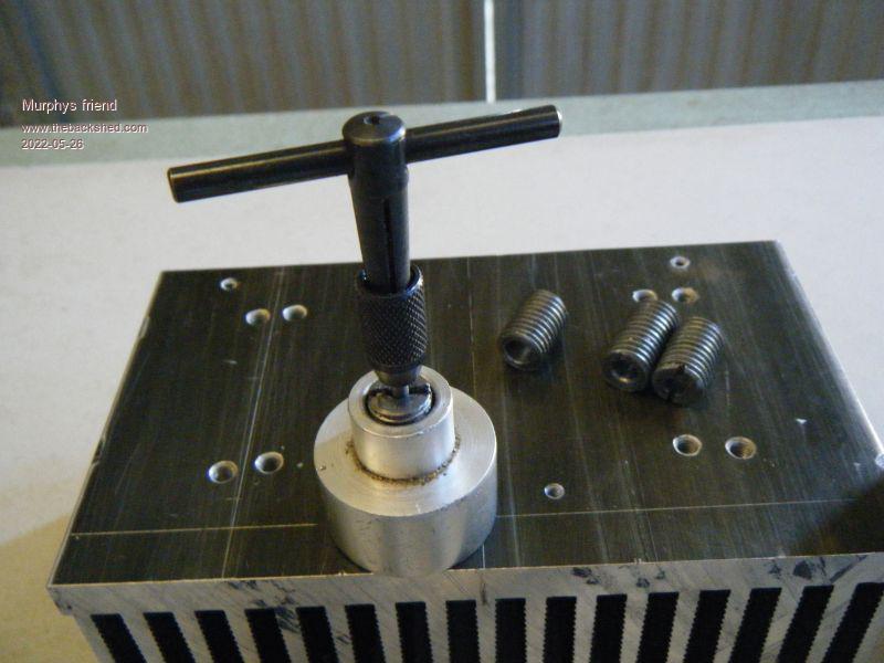 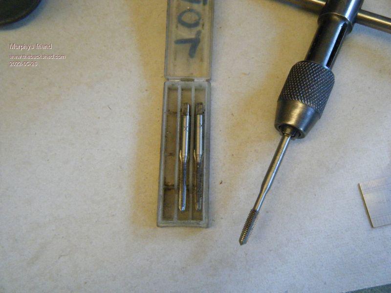 |
||||
| pd-- Senior Member Joined: 11/12/2020 Location: AustraliaPosts: 122 |
Good old fashioned soap has always been my goto lube for taping aluminum. just put a bit of water on one side of the bar and rake the tap across it. |
||||
| rogerdw Guru Joined: 22/10/2019 Location: AustraliaPosts: 803 |
Thanks for the encouragement Bruce, I think I have enough momentum now to see it through ... plus I've spent enough on the bits and pieces that I really need to see a return on it all. And I'm sorry to hear of your health issues and having to give up your licence, that must be hard to deal with. Thanks Aaron for helping Bruce out ... friends can make such a difference when we're having a hard time. I hope I can get my wiring to look as neat as yours when I get to that stage too ... your layout has given me some ideas, along with those analogue meters. Cheers, Roger |
||||
| rogerdw Guru Joined: 22/10/2019 Location: AustraliaPosts: 803 |
Thanks Klaus, some really useful hints there. You've almost convinced me to buy a couple new 3mm taps and have a go. My aluminium should be here next week so I'll be abe to get started on the cutting, drilling and tapping soon. Now I just need to work on my patience. I'll also attempt to make a couple jigs to help keep the tap square, that seems to be a big issue normally for me, trying to keep everything straight. Thanks PD, I'll give that a try too. Cheers, Roger |
||||
