
|
|
Forum Index : Electronics : Nanoverter and Backfeeding with a GTI
| Page 1 of 7 |
|||||
| Author | Message | ||||
Madness Guru Joined: 08/10/2011 Location: AustraliaPosts: 2498 |
It has been a long time since I have been active here due to issues I have had and I won't bore anyone with the details. I have just built a new inverter with 3 Aerosharp Toroid Cores. 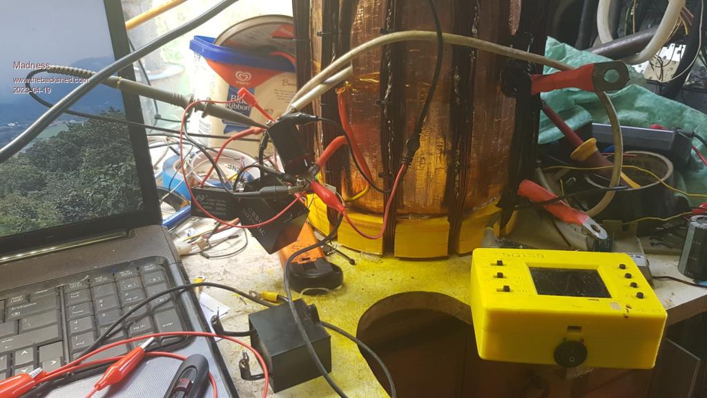 I have used the large choke cores from the Aerosharps to make these chokes. 12 Turns of 30 1.6mm wire which gives a total of 60mm2. 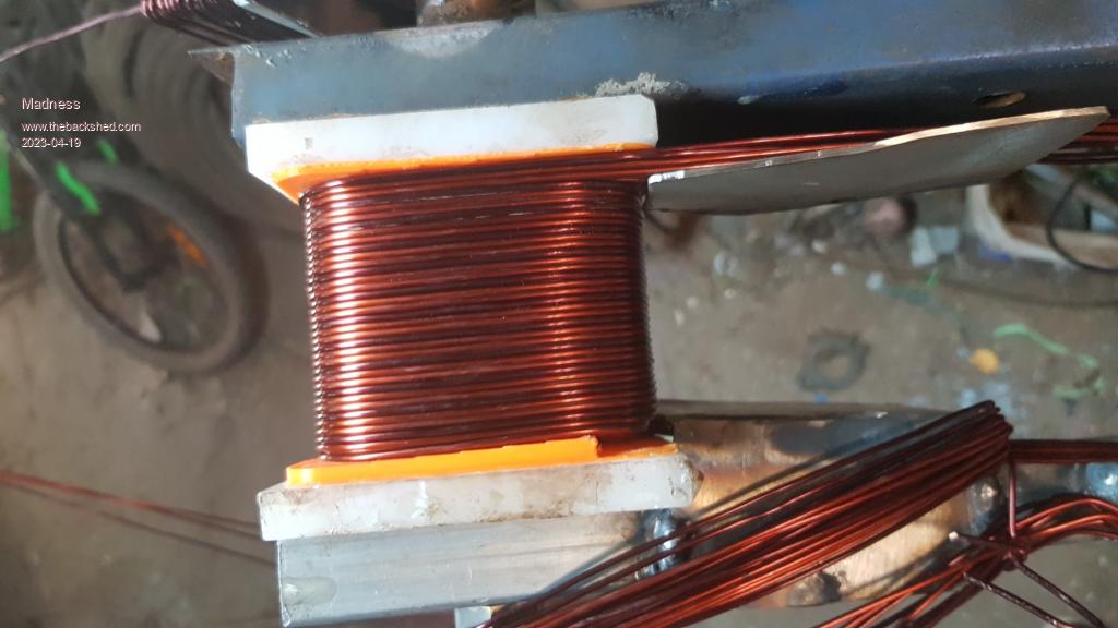 I have managed to shoehorn this into 2 Aerosharp cases with one choke on either end of the Toroid and power board output.  This runs perfectly as a standalone off-grid inverter it is almost completely silent and gives the best possible sinewave output. 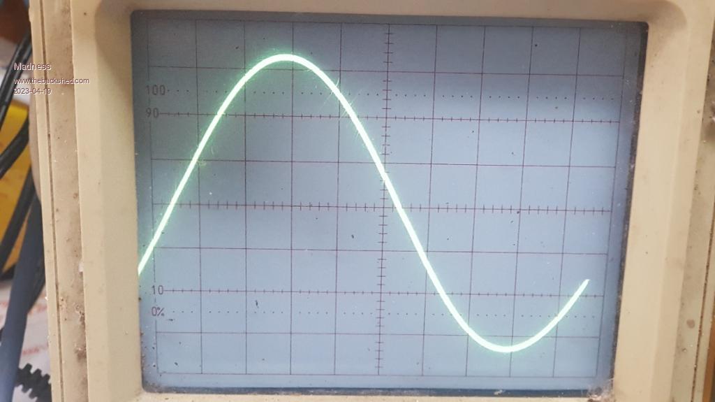 There is no sign of any wobbles at zero crossing etc just at no load the peaks of the sine wave are slightly flattened. In spite of it running so well I am having issues with back-feeding from a GTI. I have only tried one with a few hundred watts of power available so far. If there is no load on the inverter the GTI tries to connect but the sine wave has like another small sine wave following the path of the main sinewave like this. Please excuse my lack of artistic ability, it does this for about 1/2 of second and the GTI quits and retries. 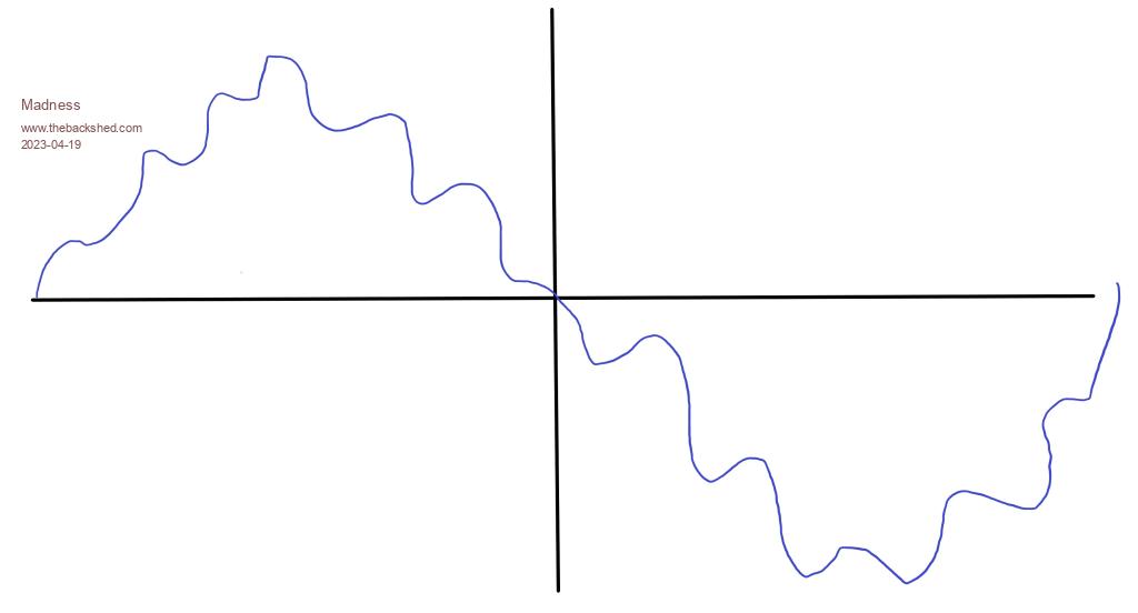 It will run fine if the is more load on the inverter than the GTI is able to output. But if running like this and I reduce the load the inverter makes some oscillating groaning sounds for a second and the GTI quits. I am using the Murphy code for Nano1 uploaded in the last month. Has anyone had success with back feeding? I am planning to work on syncing with a generator but if it won't backfeed then that won't do what I want. Edited 2023-04-19 11:46 by Madness There are only 10 types of people in the world: those who understand binary, and those who don't. |
||||
| Madness Guru Joined: 08/10/2011 Location: AustraliaPosts: 2498 |
Also does anybody know what the hack is that is mentioned here Hack "nano2 code oversees things and shows stuff on the LCD. I have many variations of nano2 code that is for I2C LCD, serial LCD, a AC curent sensor (that needs a simple hack on the nanoverter board) and others." There are only 10 types of people in the world: those who understand binary, and those who don't. |
||||
| Madness Guru Joined: 08/10/2011 Location: AustraliaPosts: 2498 |
I had another look at the waveform when the GTI connects. This is a better drawing of it. 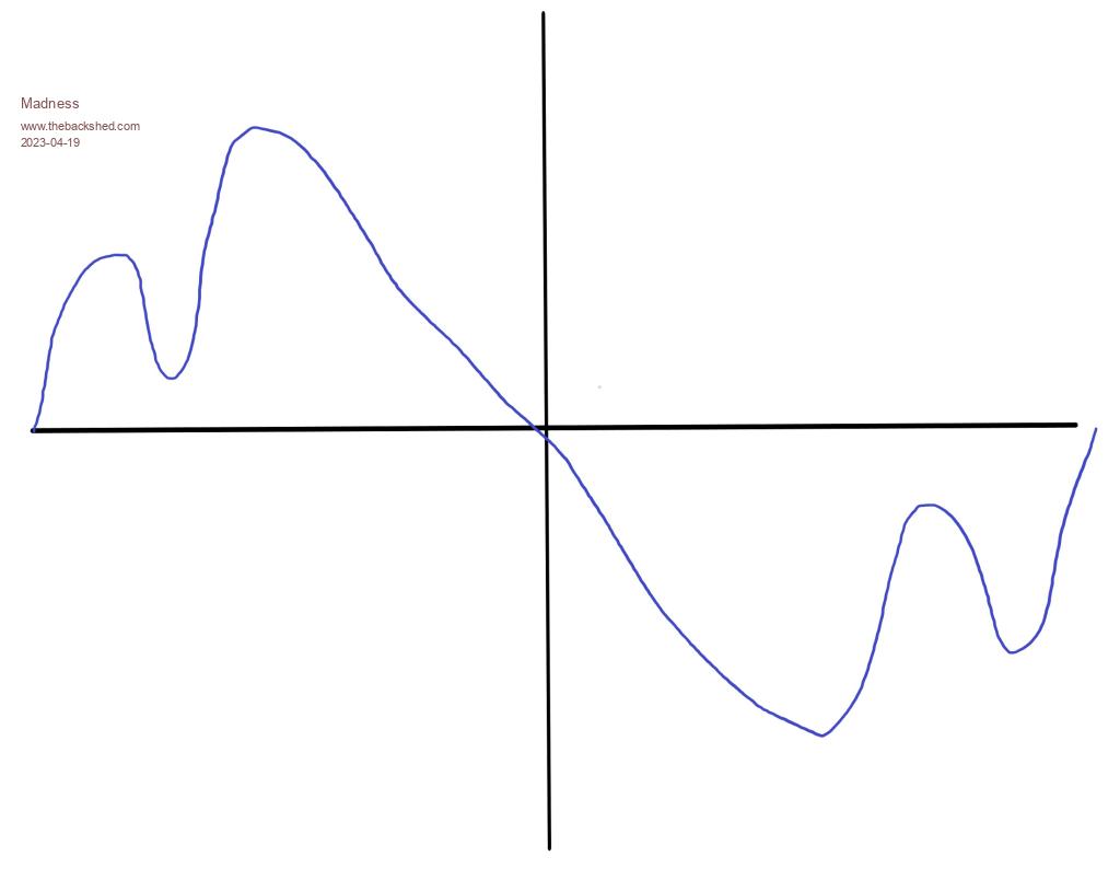 The image above is more like what happens after the GTI is connected with a load already on the inverter and then the load is turned off. I have tried it with the V7 No Bessel version of the Nano1 code and it is the same. Edited 2023-04-19 15:03 by Madness There are only 10 types of people in the world: those who understand binary, and those who don't. |
||||
| poida Guru Joined: 02/02/2017 Location: AustraliaPosts: 1480 |
Madness asked me a question via PM and I think it's best to answer here. The nano1 code drives the inverter only. The nano2 does the inverter on/off, low voltage cutoff, sends data to the LCD etc. So the sinewave PWM output is generated by nano1. Every zero crossing of the AC output, code executes to see AC output voltage and uses that measurement at that time to feed into the closed loop control. This means the AC output will be immediately modified for the next 1/2 wave to more closely follow the setpoint. The modification is a uniform increase or decrease of the AC voltage for that 1/2 of the wave. Let's say the inverter is running in stable way. At time 0.01 Seconds (zero cross) Vfb is a little high. The loop control calculates a smaller scale factor for all of the 200 pulse's widths for the next 1/2 wave and that scale factor stays constant for that period of time. At time 0.02, again a zero cross, Vfb shows it's too low. The control loop works out a slightly larger scale factor for the next 200 pulse widths and this is now applied to the output. So the control loop sets a scale factor for the PWM widths that is constant for each 1/2 cycle, or 200 pulses. 50 Hz AC output and 20,000 Hz PWM means 400 PWM pulses for the complete wave. And so it's 200 pulses for the first 1/2 of the AC wave and 200 for the 2nd half. The control loop performs corrections at 100 Hz and each correction is constant for the next 0.01 second (or 1/2 wave, or 200 PWM pulses) So I think the distorted waveform seen above has origins from the electrical interaction of some parts of the system. If the nanoverter was upsetting things, I would expect much slower changes, not 4 or 5 dips in AC voltage per 50 Hz cycle. How slow? Something like AC voltage varying up and down at 2 Hz or 3 Hz and maybe up to 5Hz. The frequency response of the control loop, when using the op-amp low pass filter, is not fast. I recall doing some transient response tests of the loop and got some good DSO captures of the AC voltage before, during and after I apply a sudden load. I think this post shows what is happening. The light Blue trace is the scale factor and you can see it stays constant for each 1/2 cycle. https://www.thebackshed.com/forum/ViewTopic.php?PID=104481#104481#104481 Edited 2023-04-19 15:53 by poida wronger than a phone book full of wrong phone numbers |
||||
| Madness Guru Joined: 08/10/2011 Location: AustraliaPosts: 2498 |
Thanks for the help, I will try running it on a EG8010 in Unipolar modulation mode and see how that compares. I saw somewhere a long time ago in some documentation about the EG8010 that they used 2 chokes with Unipolar modulation. There are only 10 types of people in the world: those who understand binary, and those who don't. |
||||
| Murphy's friend Guru Joined: 04/10/2019 Location: AustraliaPosts: 678 |
Gary, I do back charging (via GTI) here on a daily basis, often 2KW or so if the sun cooperates. The nano inverter (latest code) *does* have issued with that, the wave form has a reverse kink (smaller than that on your sketch above) only on one side of the sine slope. That does produce noise in the nano inverter but it keeps on running fine. There was also noise from my GTI but I seem to have cured that by back feeding via an isolation transformer. I use a standard 3KW Aerosharp toroid (unmodified) for that. GTI to 230V primary, Nano inverter to 250V secondary. This is a recent addition and so far no problems. On my 6KW (2 stack) nano inverter I have a choke in each primary leg. One side has a 180uH choke, made from double large aerosharp chokes (made into an E core) with 18 turns of 40mm sq. The other side has a 2 stack powdered iron toroidal choke, cores similar what KeepIS uses. (C8610125) That one has 40uH, 7 turns of 25mm sq wire. Without back charging (when the battery bank is full) that inverter is virtually silent now. The microwave does still mess up the sine wave. Fitting a 3 stack toroid & parts into a doubled Aerosharp case does look like a challenge, I'm surprised you persisted. I've given those ss boxes a miss long ago, have still some taking up space on the shed shelf though. Its not that hard to weld up an angle frame and make your own enclosure to whatever dimensions you want. You can see how on my (tinker's) built. |
||||
| Madness Guru Joined: 08/10/2011 Location: AustraliaPosts: 2498 |
Hi Klaus, What kind of GTI are you using? For a long time I have been using 3 5KW ABB Aurora GTI's with my EG8010 Inverter. It runs flawlessly with no waveform issues, I get away with running 3 of them as I divert power once a set battery charge current is exceeded. Also, I regulate the PV input if my HWS thermostat has switched off or if for any other reason, there is too much battery current. I am in the process of trying the EG8010 in Unipolar mode in this new inverter to see if there is any issue relating to chokes or the Toroid itself. It does run so well until the GTI connects, so I fully expect the Unipolar EG8010 will run fine as well. But I really want to get the Nanoverter working so I can work towards syncing with a generator and back-charging. One thing I have not fitted is the filters to the inverter output, two reasons are 1, there is no room for them in the case and secondly, the output is so clean and perfect that I don't think it is needed. There is zero trace of the 20khz SPWM and absolutely no kinks and wobbles at zero crossing that plagued me previously. The case is built, it was a bit of work but I got there, if I made it larger it would not have fitted on the wall in the space I had available anyway. That spot was previously occupied by 2 Trace 4.5KW inverters from last century that have reached their use buy date. I have polished up the Stainless steel and I don't need to worry about painting it or having it rust. The Stainless steel is easy enough to work with as I have a MIG welder that came with Argon gas and stainless wire. Getting the right cutting discs and drill bits also makes it not much different than working with normal steel. Here is a little fun fact for you also, way back you said having the capacitors inside the heatsink was a bad idea due to heat. In the last 5 or 6 years my main inverters heatsink has never, not even once exceeded 40 degrees. So the air flowing through the heatsink had to be less than 40 degrees which means the capacitors were never at any risk of getting anywhere near a temperature that would cause an issue. As I have never had a cap fail also confirms that I don't need to worry about it and my inverter has to earn its keep. I know the temperature has never gone above 40 as my control card records the highest temperature for both the caps and the toroid which has had a maximum of 61 degrees. There are only 10 types of people in the world: those who understand binary, and those who don't. |
||||
| Murphy's friend Guru Joined: 04/10/2019 Location: AustraliaPosts: 678 |
Gary, my GTI inverter is a 3 string input Motech 3.6KW which I got free, not working, but could repair as only the relays were shot. Good to hear that nothing gets too hot in your fancy ss cases, I wonder if the fan has to run a lot to keep it that way. I still believe that caps between heatsinks is not the best place for them IF the heatsinks get hot. Obviously if you make them big enough that might not be the case. However, if I remember right, you cut away some of the fin area to make space for the caps - odd way to reduce capacity of a perfectly good heat sink?  As you know, I also have gone away from the full bridge power board idea and am using busbars so I do not need expensive 2 oz PCB's. To each his own. I have filters fitted to the AC output in the hope the microwave distortions go away. These filters are re cycled ones so no expense involved and there is plenty of space in my cabinet for them. Good luck with generator synching, I have never had any success with that once it was meant to share power. It synched OK while idling but that's no use. I'm now using a big battery charger powered from the generator should I require that back up. |
||||
| Solar Mike Guru Joined: 08/02/2015 Location: New ZealandPosts: 1228 |
A thought: If the GTI doesn't get in phase fast enough with the inverter AC output when back feeding via the transformer, the conducting mosfets may not be conducting such that the rectified back fed AC is the correct polarity to charge the main bank caps thus partially shorting out or placing a great load on the GTI and shutting it down. Cheers Mike |
||||
| Madness Guru Joined: 08/10/2011 Location: AustraliaPosts: 2498 |
Hi Mike, The GTIs never have an issue with the EG8010 inverters in my experience. However, this is a new inverter with a bigger toroid and chokes than anything I have tried before. So far I have only had it running with the Nanoverter control board, tomorrow I will get the EG8010 control board working on it and see how it behaves then. As far as I am aware the GTIs have quite tight tolerances with phase syncing and voltage and will disconnect very quickly if something is not just right. There are only 10 types of people in the world: those who understand binary, and those who don't. |
||||
| Madness Guru Joined: 08/10/2011 Location: AustraliaPosts: 2498 |
All bar one of the Aurora GTIs I have were dead when I got them. Most common fault is aging relay contacts getting hot and causing the solder melt. Another had suffered a lightning strike but only needed MOVs replacing. Also I have software that allows getting into the brains of them and you can do a lot of monitoring and tweaking through that. They can also be reprogrammed to work with a wind generator which I hope to be trying out in the near future. There are only 10 types of people in the world: those who understand binary, and those who don't. |
||||
| Solar Mike Guru Joined: 08/02/2015 Location: New ZealandPosts: 1228 |
Didn't the original Nanoverter software emulate the EG8010 in its H-Bridge switching, then later it was altered to be more efficient with a change in the way the mosfets were switched; Perhaps that has something to do with it.... Mike Edited 2023-04-19 22:47 by Solar Mike |
||||
| Madness Guru Joined: 08/10/2011 Location: AustraliaPosts: 2498 |
Mike I had wondered about that I am reading though everything I can find about the code to get a better understanding. This morning I got a EG8010 test rig running using Unipolar with just 4 MOSFETs in total with smaller chokes on each output of the power board. This has worked with the GTI up to 200W so far and connects and operates without any issue. I have not had run any load before connecting the GTI. The sinewave is good, I just want to confirm this is all okay before fitting this control board to the big inverter. There are only 10 types of people in the world: those who understand binary, and those who don't. |
||||
| Madness Guru Joined: 08/10/2011 Location: AustraliaPosts: 2498 |
I said above I was going to try Unipolar on the EG8010, what I should have said is BIPOLAR, must be going mad. The Bipolar modulation requires VFB from each side of the output but they only show it being used with a high voltage type inverter. 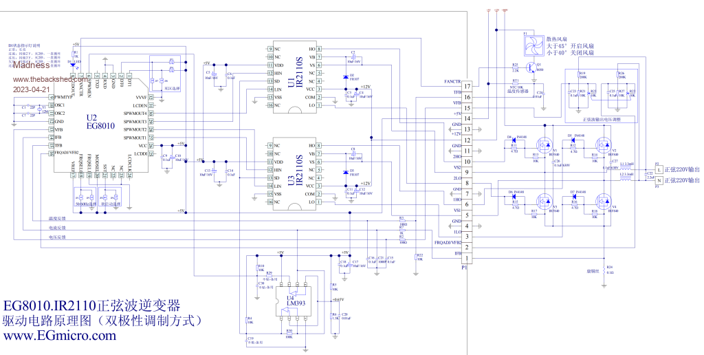 I have tried this but get a sine wave that looks like it has not had the SPWM filtered out but is much wider, I ran out of time on it today to get any further. I used the VFB circuit as per above on the toroid output. Previously I had just enabled Biploar with just the standard VFB we have been using forever on the EG8010, that gave a sinewave that had the top half looking normal but the bottom half was wobbly after zero crossing and the amplitude was reduced to about 2/3 of what is should be. I tried linking together both VFB and VFB 2 and got the same really wide sinewave as per above. Maybe something else is faulty causing that. Poida is there possibly a different way in the code to produce the SPWM? I see here https://www.thebackshed.com/forum/ViewTopic.php?TID=9409&P=16#127475 you were working with different methods. If the Closed loop for the voltage control is basically the same as the EG8010 then am I right in thinking that the SPWM is the only possible factor assuming the hardware is functioning correctly? I have tried the standard EG8010 setup with the test set and the new inverter I have built and they run fine running normally and back feeding. They also run perfectly with the Nanoverter driving them and will work with a GTI but runs into problems when they try to backfeed. There are only 10 types of people in the world: those who understand binary, and those who don't. |
||||
| Madness Guru Joined: 08/10/2011 Location: AustraliaPosts: 2498 |
Turned out the really crazy waveform was caused by a bad connection on one side of the toroid secondary. But still no luck in getting the EG8010 to play nicely in what they call Bipolar mode. I have been trying to find out if the type of SPWM modulation is what is preventing the Nanoverter from back feeding, but I have not found an answer as yet. For those who may be interested this video gives a very good explanation of various methods to produce a sinewave. Bipolar and Unipolar for single phase inverters There are only 10 types of people in the world: those who understand binary, and those who don't. |
||||
| poida Guru Joined: 02/02/2017 Location: AustraliaPosts: 1480 |
I can now help with this. I wanted a "proper" AC current sensor to give AC current readings, not the diode bridge + current transformer that was designed into the nanoverter board. I spend a while trying to make it work and it was poor, the Vf of the diodes made it very non-linear. the hack: first, remove R36 (2K2) I fit a 3 pin 0.1" header to pins of the unused MAX232, pins 14,15,16 This gives me +5V, Gnd and unconnected for now. I run a 2K resistor from the unused pin to R36 pin that goes to the Nano analog input. This now gives me a 3 pin header that I con connect various current sensors to, using my standard 3 pin wiring (5V, Gnd and signal) Leaving C39 in place we have a nice RC low pass filter on this input as well. The nano2 code already has support for a linear AC current sensor You tell it the DC offset and the linear gain via the menu and you are good to go. Of course we will not be able to get AC power (in Watts) since we need to multiply current by volts over the entire waveform. So instead we can get AC VA if we want. I use a DIN rail wattmeter that outputs pulses for both Watts and VA to get true inverter AC output power. 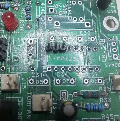 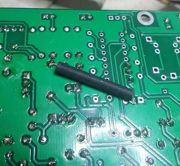 wronger than a phone book full of wrong phone numbers |
||||
| Madness Guru Joined: 08/10/2011 Location: AustraliaPosts: 2498 |
Thanks Poida, So a LEM current sensor from a Aerosharp will work with this? I ended up getting the EG8010 to run in Bipolar but it is very heavy on the DC current. So I am giving up on trying that idea to test if that type of modulation is compatible with GTI back feeding. Next step I will try is hacking the early 2X Sine code to run as Nano 1. There are only 10 types of people in the world: those who understand binary, and those who don't. |
||||
| poida Guru Joined: 02/02/2017 Location: AustraliaPosts: 1480 |
here is the 2x sine PWM It works as follows: same pin functions as nano1 code. on inverter start, both 1/2 bridges output 1/2 DC supply to the primary. Since these 2 voltages are equal, no current flows through primary. Then soft start happens, gradually making the 50 Hz AC appear on the primary outputs (V1 and V2) V1 is 180 deg out of phase to V2, so we get the inverter output. This code drives both 1/2 bridges with 20kHz PWM so there is 2x switching losses. nano_1_alt_mod_no_bessel_mike.zip wronger than a phone book full of wrong phone numbers |
||||
| Madness Guru Joined: 08/10/2011 Location: AustraliaPosts: 2498 |
Yes no problem regarding switching losses I understand that, but if this version works with the GTIs then that is a very small price to pay. Now I have run out of time today but I have got the code above running on my test rig, it is running nicely but the AC voltage won't go above 182. Until I get the voltage sorted out a GTI is not going to connect. I had changed R32 previously to 680 from 1K ohms as I am using a 12V transformer for VFB. Need to look at the code later to see what is going on there. Thank you Poida for the file. There are only 10 types of people in the world: those who understand binary, and those who don't. |
||||
| Madness Guru Joined: 08/10/2011 Location: AustraliaPosts: 2498 |
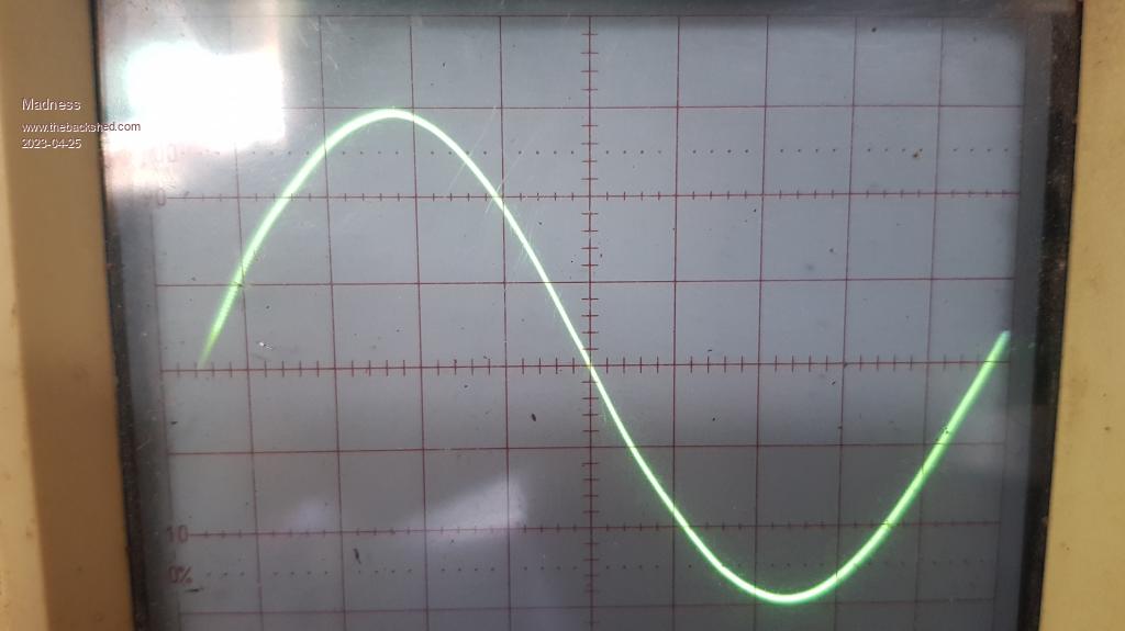 Just another sine-wave photo? Yes, but this is a sine-wave generated by the 2XSINE code above on a Nanoverter with a GTI Connected! It is running as smooth as silk, no growling, just connected and ran with no change to the sinewave at all. This is with no load just the GTI and oscilloscope probe connected to the inverter output. ATM it is cloudy and the GTI is only making around 50W ATM. I will let run all day and see how it goes. There is no way it would work like this with the V7 Nano1 modulation, I know that version runs really nicely but it does not want to play with a GTI. To get the code above to work I had to change u = 20000.0 * sin(t); to u = 23000.0 * sin(t); This was to get the AC up from 200V to 230V, I am not sure if this is the best way to do this I hope Poida can verify if correct or not. It may need to go higher as I don't think there is any headroom for a load on the inverter as it is now. Edit. I have now seen over 300W back-feeding and all is well. Edited 2023-04-25 10:17 by Madness There are only 10 types of people in the world: those who understand binary, and those who don't. |
||||
| Page 1 of 7 |
|||||
| The Back Shed's forum code is written, and hosted, in Australia. | © JAQ Software 2026 |
