
|
|
Forum Index : Microcontroller and PC projects : STM32L4 circuit
| Page 1 of 2 |
|||||
| Author | Message | ||||
lew247 Guru Joined: 23/12/2015 Location: United KingdomPosts: 1709 |
Would people be so kind as to check my circuit and see if you can spot any mistakes please? It's for an STM32L431CCT6 driving an AX1201728SG stepper motor controller It has USB to Uart, 5V boost converter, HC-12 and DS18B20 as well Hopefully I've got the circuit so it can be used both as a console and programming via usb 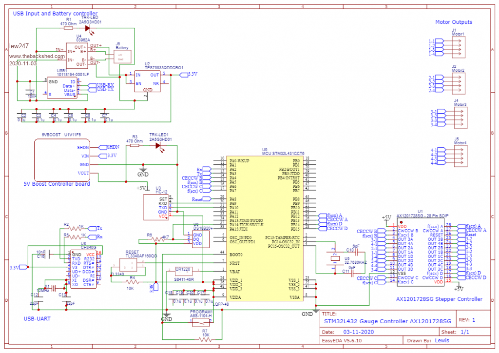 Schematic.pdf |
||||
| lizby Guru Joined: 17/05/2016 Location: United StatesPosts: 3784 |
I can't judge overall, but where is your SHDN line coming from? To satisfy curiosity, what is the application? [EDIT: Oh, I see it's for your gauge control task.] Edited 2020-11-04 00:15 by lizby PicoMite, Armmite F4, SensorKits, MMBasic Hardware, Games, etc. on FOTS |
||||
| lew247 Guru Joined: 23/12/2015 Location: United KingdomPosts: 1709 |
Well spotted It "will be" coming from pin 43 I just learnt to check what is being deleted when you press the delete button Deleted the whole project! have to start again from scratch  Thankfully I can use the pdf I just downloaded from here as a basis to start again 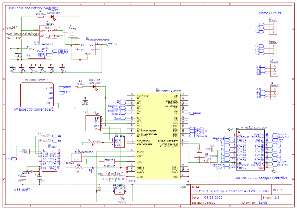 |
||||
| Volhout Guru Joined: 05/03/2018 Location: NetherlandsPosts: 5931 |
C187... C20 do not gave ground connection reset switch connected wrong (R4 to pin 7, switch pin 7 to ground) CH340 pin 1 not connected to ground U1 RESET pin should have a resistor to force reset when power applied until STM32 executes code. Same for SHDN pin. The boost convertor should not start until the STM commands. U2 pin 2 (GND) not connected to GND Maybe add a jumper to HC12 pin 5 (SET) so you can configure it from the STM32. USB1 connector seems to have a connection between pin 1 (Vbus) and pin 5 (GND), and neither is connected to GND. C10 and C11 do not have connection to GND. PicomiteVGA PETSCII ROBOTS |
||||
| lew247 Guru Joined: 23/12/2015 Location: United KingdomPosts: 1709 |
Thanks, redoing it but it will take a day or so - have to start again |
||||
| lew247 Guru Joined: 23/12/2015 Location: United KingdomPosts: 1709 |
Updated and I "think" it's all correct but I stand to be corrected 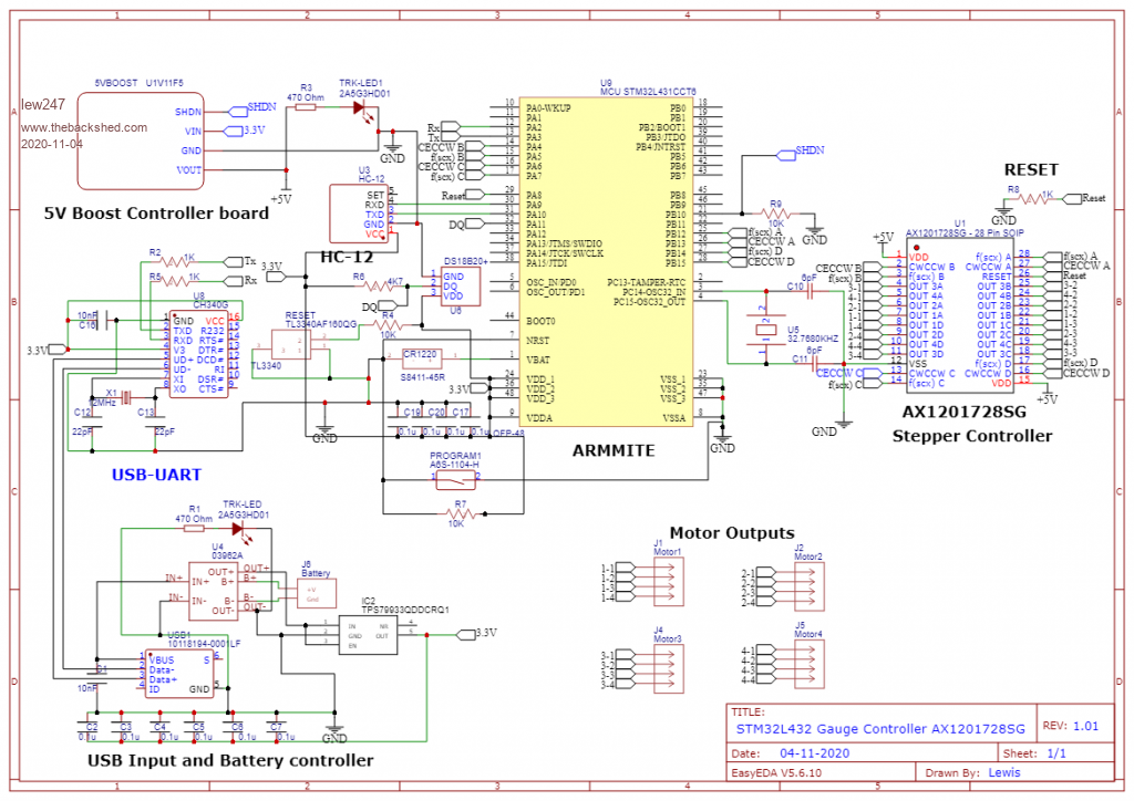 Schematic_New1.pdf Edited 2020-11-04 22:11 by lew247 |
||||
| Volhout Guru Joined: 05/03/2018 Location: NetherlandsPosts: 5931 |
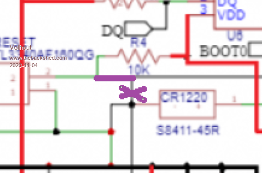
This does not make sense to me (RESET hardwired to gorund) 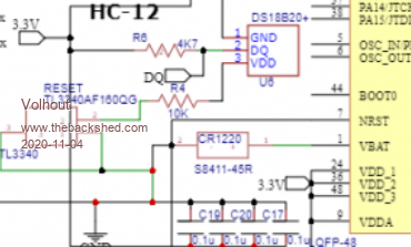 Also R7 and PROGRAM1 must connect to BOOT0 pin on STM32 R1 should connect to IN+, not IN- Edited 2020-11-04 22:17 by Volhout PicomiteVGA PETSCII ROBOTS |
||||
| lew247 Guru Joined: 23/12/2015 Location: United KingdomPosts: 1709 |
Think I've fixed the issues, hopefully made it slightly easier to see in the picture 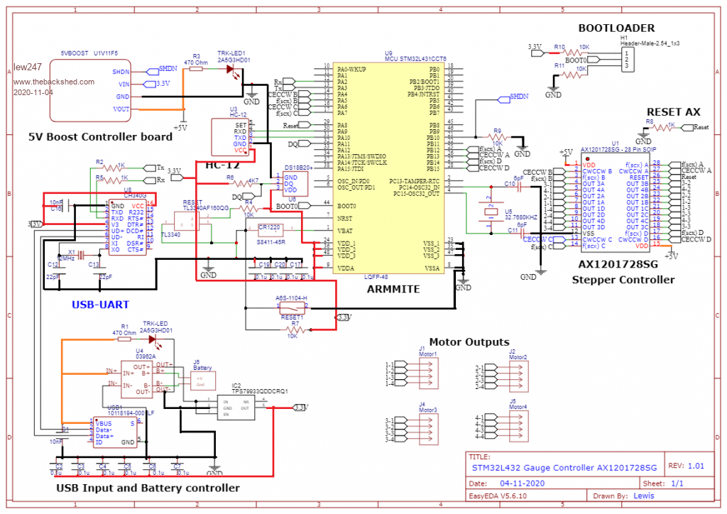 Schematic_New1.pdf Edited 2020-11-04 23:51 by lew247 |
||||
| Volhout Guru Joined: 05/03/2018 Location: NetherlandsPosts: 5931 |
 Do you have 2 reset switches ? PicomiteVGA PETSCII ROBOTS |
||||
| lew247 Guru Joined: 23/12/2015 Location: United KingdomPosts: 1709 |
Later version fixed that hopefully 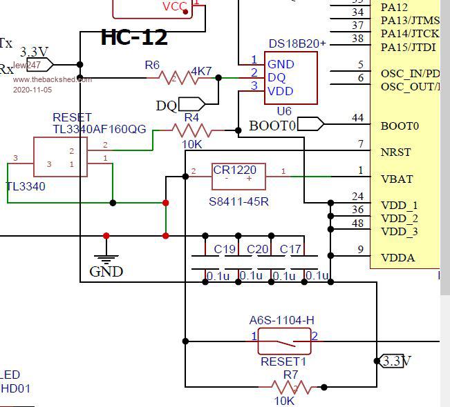 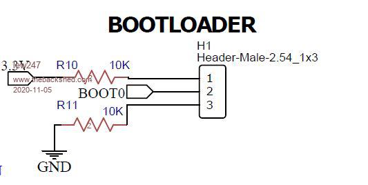 |
||||
| lizby Guru Joined: 17/05/2016 Location: United StatesPosts: 3784 |
As I read it, NRST is connected directly to 0V, and also, through a 10K resistor, to 3V3. Are you sure you want the link to the right of GND connecting up to a line which goes to the left of CR1220 and on to NRST? Something seems wrong there. Actually, as Volhout has it, the dot at "2" left of the CR1220 should not be there. (But then I'm not sure how the TL3340 should be connected.) ~ Edited 2020-11-05 01:54 by lizby PicoMite, Armmite F4, SensorKits, MMBasic Hardware, Games, etc. on FOTS |
||||
| Volhout Guru Joined: 05/03/2018 Location: NetherlandsPosts: 5931 |
The only source I found for TL3340 is a mechanical push button switch. 10k pullup to 3.3V Pushbuttonswitch to ground That should do it for reset. The other switch was originally connected to BOOT0 (probably a slide switch) Now it is also connected to NRST (if I understand the intention of the schematics right). So there are 2 reset switches. The BOOT0 now goes to a jumper. That may be better anyway. So one of the switches can be removed. And NRST must not be tied to ground directly (the dot lizby refers to). lew247 This schematic look a bit confusing, that is why it may be causing so much trouble to get it right. Maybe next time, take a bigger sheet of paper (you can select that when you start a sheet) and position the parts a bit more spacious, so you can draw lines with minimal corners, and not crossing parts (the wire over the reset switch). It is also possible to work with labels (i.e. 3V3 and GND), so all the black and red wired are not needed to be visible, and are connected in the background. Like you did with the BOOT0. PicomiteVGA PETSCII ROBOTS |
||||
| lew247 Guru Joined: 23/12/2015 Location: United KingdomPosts: 1709 |
I'm such an idiot I forgot to take the original switch out when I changed it to a jumper Yes it was a pushbutton Hopefully this should be better 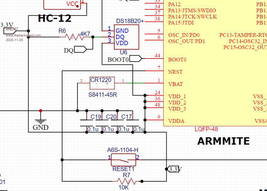 Schematic_New1.pdf EDIT: realised I had a mistake on the backup battery, corrected now Edited 2020-11-05 02:32 by lew247 |
||||
| lizby Guru Joined: 17/05/2016 Location: United StatesPosts: 3784 |
A couple of relatively simple changes could make the bottom left clearer. First move RESET1 up to the left of NRST and mirror it left to right so that pin 1 goes directly into NRST and pin 2 drops to the GND which is now directly below it. Then mirror the 3 capacitors, C19, C20, C17 top to bottom and adjust the GND line. This will produce a more normal layout with the + voltage higher in the drawing and the GND lower. ~ Edited 2020-11-05 04:02 by lizby PicoMite, Armmite F4, SensorKits, MMBasic Hardware, Games, etc. on FOTS |
||||
| lew247 Guru Joined: 23/12/2015 Location: United KingdomPosts: 1709 |
Hopefully this is slightly better I've also added battery voltage monitoring and E-Ink to display the battery voltage 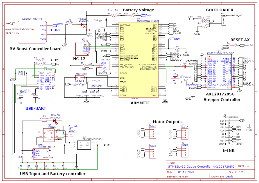 1.pdf Edited 2020-11-05 04:48 by lew247 |
||||
| lizby Guru Joined: 17/05/2016 Location: United StatesPosts: 3784 |
The top of your caps, C19, C20, C17 should connect to 3V3, and the 0V side of the CR1220 should connect to GND, not the plus side of those caps. All the VDDs, including on the DS18B20, should connect to 3V3. Edited 2020-11-05 06:11 by lizby PicoMite, Armmite F4, SensorKits, MMBasic Hardware, Games, etc. on FOTS |
||||
| lew247 Guru Joined: 23/12/2015 Location: United KingdomPosts: 1709 |
Thanks  I never spotted that one, I love how helpful this forum is and everyone on it. Once I've got the circuit 100% correct I've got to work on converting it to a pcb and then once it's ordered learn how to program STM32's I got one of the Nucleo boards to play with but haven't powered it up yet 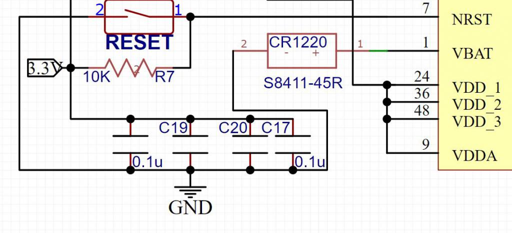 |
||||
| lizby Guru Joined: 17/05/2016 Location: United StatesPosts: 3784 |
Not quite enough shown to see if you caught my edit--all the VDDs, including on the DS18B20, need to connect to 3V3. PicoMite, Armmite F4, SensorKits, MMBasic Hardware, Games, etc. on FOTS |
||||
| lizby Guru Joined: 17/05/2016 Location: United StatesPosts: 3784 |
Which one? The L432KC is breadboard-friendly. With the L476RG, it's flying leads. PicoMite, Armmite F4, SensorKits, MMBasic Hardware, Games, etc. on FOTS |
||||
| lew247 Guru Joined: 23/12/2015 Location: United KingdomPosts: 1709 |
It's the STM32L432 ĀNucleo-L432KC I don't have a breadboard lol, just jumper cables The PDF can be zoomed to whatever size is required 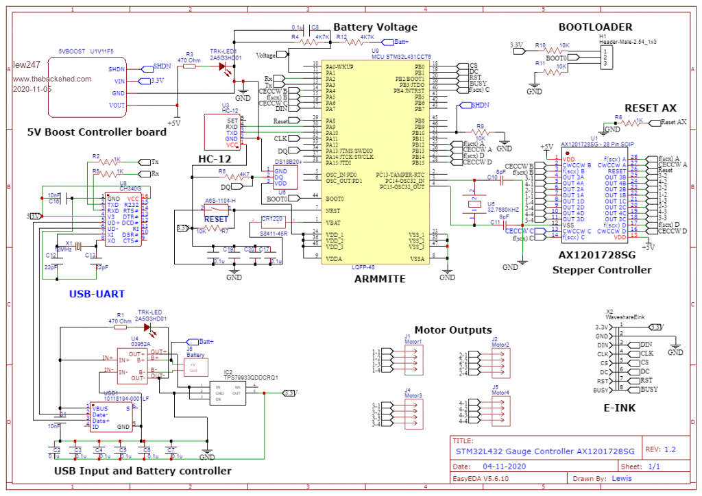 1.pdf Edited 2020-11-05 07:03 by lew247 |
||||
| Page 1 of 2 |
|||||
| The Back Shed's forum code is written, and hosted, in Australia. | © JAQ Software 2026 |
