
|
|
Forum Index : Microcontroller and PC projects : PicoMite Alpha Firmware - a27 onwards - starting on displays
| Author | Message | ||||
| Mixtel90 Guru Joined: 05/10/2019 Location: United KingdomPosts: 8953 |
I suspect they decided to use the switcher because od the intended market, it wasn't a mistake. The original Pico has no audio output as it's primarily a microPython-based controller board. However, a source of 3.3v is needed to feed IO as the RP2040 has no 5v tolerant pins. The switcher provides 300mA for the user, which I regard as pretty generous really. A linear to feed just the RP2040 might have been a cheaper option but the user would have had to source 3.3v. Of course, once it gets upgraded to a PicoMite the hardware limits start to get pushed. :) That's why they gave us PFM/PWM switching the 3.3EN pin and the ability to easily connect backup battery supplies. :) Mick Zilog Inside! nascom.info for Nascom & Gemini Preliminary MMBasic docs & my PCB designs |
||||
| Volhout Guru Joined: 05/03/2018 Location: NetherlandsPosts: 5981 |
PWM signals can be used to make simple analog signals by using their pulsewidth to convert a voltage (the amplitude) by a low pass filter into a an analog voltage. The result is a multiplication of duty cycle and digital power rail voltage. Improving the audio can be achieved by improving the power rail (linear regulator), but also by taking it completely out of the equation. In example:if you pass the PWM signal through a logic buffer gate, powered from a clean voltage, you achieve the same (without modification the the picomite). The clean voltage can be a 100ohm/100uF filter on 3.3V or 5V, the buffer a 74LVC04. An other alternative is clamping the 3.3V PWM signal to a clean voltage (in example a 3.3k series resistor to a silicon diode (1N4148), the same way Geoff made VGA video on the CMM1). Of coarse the amplitude will be 5x lower (3.3V->0.6V), but noise will be 100x lower (diode rd=33ohm at 0.75mA, Rseries = 3.3k). A S/N gain of 100/5=20x. As most amplifiers have gain, the lower level is not a problem. Edited 2021-07-05 06:12 by Volhout PicomiteVGA PETSCII ROBOTS |
||||
| phil99 Guru Joined: 11/02/2018 Location: AustraliaPosts: 3318 |
Getting a clean Vcc is a major part of the solution but in other applications I and many others have found getting a clean ground is also important. If a single point or star ground is impractical then perhaps an optocoupler may be the best way to eliminate digital noise. It would need to be a fast one to keep up with the PWM without adding it's own distortion. |
||||
| Volhout Guru Joined: 05/03/2018 Location: NetherlandsPosts: 5981 |
You actually want to isolate everything that is related to the ground and power rail. If you choose an optocoupler it should be fast: use digital optocoulers. There are the classic ones such as 6N136, but these required high LED currents (for picomite: require a driver transistor/buffer), and the modern ones such as TLP2345/TLP2745 that can be driven directly from the picomite since they only require 2mA LED current. But that is not needed. In the audio system you can create your own star ground (and you should) with a simple buffer, as described earlier. As long as your ground noise and 3.3V noise stay outside the logic levels of the buffer chip. 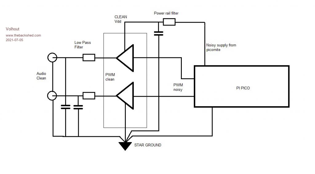 Volhout P.S. I have drawn a single stage low pass filter, but (depending the PWM frequency) you may need a multistage filter. A single RC is only 6dB/octave. If you need 60dB wideband S/N you need 10 octaves between your highest audio frequency and the PWM frequency. 10 octaves = 2^10 = 1024. For 8kHz your PWM should run at 8MHz. Many of these cheap solutions (single RC) rely on the fact that the human ear cannot hear anything above 30kHz anyway. Edited 2021-07-05 16:49 by Volhout PicomiteVGA PETSCII ROBOTS |
||||
| matherp Guru Joined: 11/12/2012 Location: United KingdomPosts: 11609 |
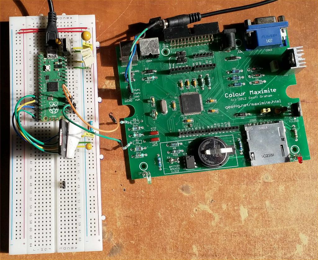 PicoMite with low dropout linear regulator (LM1084) taking power from VBUS and feeding 3V3. 3V3_EN tied to GND. 10uF across input and 100uF + 2 x 0.33uF + 0.1uF across output. SDcard connected to 3V3 via 4R7 resistor with 100nF and 33uF caps across the SDcard power. Using Colour Maximite for the audio low pass filter by connecting to R7 and R8 Perfect sound with no noise |
||||
| thwill Guru Joined: 16/09/2019 Location: United KingdomPosts: 4370 |
Thank you for taking the time to reply Peter, I'll try and remember to do that the next time I have the hardware out. I sent my original Maker board back and the replacement is still in the packaging - I've just been using a Pico plugged into a breadboard with a breadboard power supply independently powering SD card and other peripherals. Best wishes, Tom MMBasic for Linux, Game*Mite, CMM2 Welcome Tape, Creaky old text adventures |
||||
| Volhout Guru Joined: 05/03/2018 Location: NetherlandsPosts: 5981 |
Where is your ground connection between Picomite and colour maximite ? Is that running via the USB ground ? PicomiteVGA PETSCII ROBOTS |
||||
| matherp Guru Joined: 11/12/2012 Location: United KingdomPosts: 11609 |
Sorry to mislead: I'd pinched the gnd link for something before I took the picture |
||||
| phil99 Guru Joined: 11/02/2018 Location: AustraliaPosts: 3318 |
To Volhout, Your circuit should be the perfect solution. Re human hearing. In my age bracket 10kHz would be an optimistic limit. |
||||
| Glen0 Senior Member Joined: 12/10/2014 Location: New ZealandPosts: 101 |
Re Picomite Doc @Volhout Got a couple of these units the other day to experiment with. Thanks for the summation document, it got me started and I have copied the latest UF2 file to the device but now need to know how to program it. I will be using Tera Term but I need to know if I have to connect to some of the IO pins or whether it can be done over the USB port provided. Could you please elaborate a little on how to program the Pico. |
||||
disco4now Guru Joined: 18/12/2014 Location: AustraliaPosts: 1130 |
It can only be connected to via the USB. When you plug it in a new COM port should become visible for teraterm. Connect using the new COM port and you should have the command prompt. F4 H7FotSF4xGT |
||||
| Volhout Guru Joined: 05/03/2018 Location: NetherlandsPosts: 5981 |
Set Teraterm (Serial port setup) to 38400 baud, set (Terminal setup) new line to CR for both receive and transmit. Press <enter> and you will be presented with a command prompt. Press F4 and you are in the editor. Type your program, and run it with F2. Different from the 28pin micromite, the program storage is not persistent. Zo if you power off, the program is lost. Unless you store it in flash. FLASH LIST gives you the option of 10 program slots. FLASH SAVE 1 will save you current program on flash (slot #1) FLASH LOAD 1 will load it back from slot #1. Happy programming... PicomiteVGA PETSCII ROBOTS |
||||
| TrevorC Newbie Joined: 15/07/2020 Location: United KingdomPosts: 18 |
when using the editor the F1 save option does not save my changed text. Using the save command works as it should. Any one else having this problem ? |
||||
| Volhout Guru Joined: 05/03/2018 Location: NetherlandsPosts: 5981 |
In the Micromite F1 programs the program in the editor in flash. In the Picomite F1 programs the program in the editor in RAM. To get it save into flash use F1, then type FLASH SAVE n (n is 0..9). Volhout PicomiteVGA PETSCII ROBOTS |
||||
| TrevorC Newbie Joined: 15/07/2020 Location: United KingdomPosts: 18 |
Thanks. I was wrongly expecting the F1 save to write to a SD card like a CMM2 forgetting that a sd card my not be fitted so it makes sense now. |
||||
| Glen0 Senior Member Joined: 12/10/2014 Location: New ZealandPosts: 101 |
Thanks for the help. I will try get to this tomorrow. Neither Tera Term nor windows sees the Pico. Is there an easy way to "factory reset" the Pico |
||||
| twofingers Guru Joined: 02/06/2014 Location: GermanyPosts: 1767 |
which win version? Regards Michael causality ≠ correlation ≠ coincidence |
||||
| Volhout Guru Joined: 05/03/2018 Location: NetherlandsPosts: 5981 |
@Glen0, Can you put the firmware onto the pico ? IF yes, program the pico with the latest version. Some older versions do no start up on all picos... https://www.thebackshed.com/forum/uploads/matherp/2021-07-04_220651_PicomiteV5.07.00a48.zip After copying of the firmware onto the pico, simply do nothing, wait a few seconds. Then the memory device will disappear because the pi starts MMBasic. If you can program the pico, your cable is OK. So we can rule that out. Teraterm should see the new com port automatically (no reason to unplug and plug again. In my case COM21. 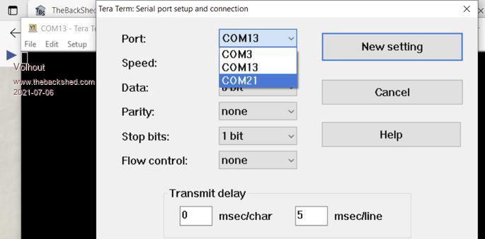 Edited 2021-07-06 21:49 by Volhout PicomiteVGA PETSCII ROBOTS |
||||
| matherp Guru Joined: 11/12/2012 Location: United KingdomPosts: 11609 |
Assuming the Pico is programmed successfully the green LED will flash at a rate of 1 second on, one second off |
||||
| Glen0 Senior Member Joined: 12/10/2014 Location: New ZealandPosts: 101 |
Thanks once again for all the assistance. From what you have been saying it looks like my pico has not been programmed successfully, Windows shows the file being copied across but the pico does not flash the green LED, it just lies there looking very dead. Tera term does not show any new com ports. If you do not know of a way to reset this unit I will pull out a fresh one and try again but be a bit more careful and methodical. |
||||
| The Back Shed's forum code is written, and hosted, in Australia. | © JAQ Software 2026 |
