
|
|
Forum Index : Electronics : Bryan's Inverter build
| Author | Message | ||||
| tinyt Guru Joined: 12/11/2017 Location: United StatesPosts: 561 |
For troubleshooting the power board, I think you can unplug the ribbon cable coming from the spwm board and apply power thru the pre-charge resistor to check if there is any change in current draw. In my case (aliexpress power board) current draw is about .05A or less. I check installed mosfets for shorts by ohming out between the gate/drain gate/source drain/source. In my case usually the ~23KHz leg of the H-bridge short out and the 50/60 Hz leg are still good. So, I have good installed mosfets that I can compare readings with. |
||||
Bryan1 Guru Joined: 22/02/2006 Location: AustraliaPosts: 2138 |
Morning Guy's, Well first thing I took TinyT's suggestion and took the ribbon cable off the power board and the short was gone  Now with the ribbon cable off I connected up the resistor bank and pretty well straight away the voltage got to Vbat Now with the ribbon cable off I connected up the resistor bank and pretty well straight away the voltage got to Vbat So it does look like the power board is OK Turned off the resistor bank and the voltage fell away pretty quick so my thought off mounting the resistor bank and using that 450 amp on/off switch. So when the inverter is off it's simple case of connecting the resistor bank as it also connected to the non contact on the switch so the caps can charge then the on/off switch can be turned on and the feed wire can be removed to take the resistor bank offline. So the job now is to get the brain board off and find where that short is. Regards Bryan |
||||
| phil99 Guru Joined: 11/02/2018 Location: AustraliaPosts: 3317 |
If no short is evident on the brain board when you get it on the bench it might be that that it was driving both high-side and low-side FETs on at the same time. Checking the gate drive signals should show if that is the case. |
||||
| Bryan1 Guru Joined: 22/02/2006 Location: AustraliaPosts: 2138 |
Well took out the brain board and to be sure replaced the 7805 as it had copped a beating over the years with the heatsink attached. Now when I power it up from the 10 amp PSU 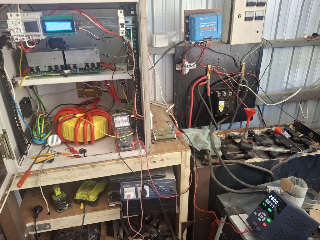 As soon as I put in the ribbon cable on the board everything is shut down and all that gobblegoot on the screen does suggest to me when I programmed the nano's the files could of been corrupted, but thats only a guess. Now both the leds come on too where the green power board led is on without the ribbon cable and when cycling the on/off switch the brainboard led does come on and off. Edited 2026-02-09 11:06 by Bryan1 |
||||
| Bryan1 Guru Joined: 22/02/2006 Location: AustraliaPosts: 2138 |
Well went and got my good laptop only to find it won't program the nano's so setup a 5 metre USB lead and used MX25 to program the nano's. I did see clearly the nano reset on the brainboard and I took the lcd off to program it. So went and tried the test again where the LCD still has that gobblegoot and when the I turn off the inverter and add the ribbon cable on starting no current draw on the PSU but the volt meter stayed in the millvolt range. I am wondering as I have moved the nano folders numerous times the files may have come corrupt so I had to go back to Sept last year in my emails to find Poida's email and now got fresh files to try. Edited 2026-02-09 13:37 by Bryan1 |
||||
| Bryan1 Guru Joined: 22/02/2006 Location: AustraliaPosts: 2138 |
Ok reprogrammed both nano's with those files from sept last year and no change at all the lcd is showing the wrong character set yet the defines in the serial file do correspond with the pinouts on Mikes LCD which I used. One would of thought once programmed the screen would come up with the initial screen. Now as soon as I put the ribbon cable on after turning off the brainboard a dead short is shown so clearly as I can't find any shorts and the way the LCD is acting I have the wrong files for this board I do think. Now the files I have nano_serial_to_parallel_LCD_2.ino pico_2_heavy_filter_bv_better_stop_prefect_symmetry.ino Regards Bryan |
||||
Revlac Guru Joined: 31/12/2016 Location: AustraliaPosts: 1282 |
Hi Bryan, Well done getting to this point in the build, I suspect the baud speed might be a bit out, nano_serial_to_parallel_LCD_2.ino is 9600 sSerial.begin(9600); I don't have this one...pico_2_heavy_filter_bv_better_stop_prefect_symmetry.ino See here https://www.thebackshed.com/forum/ViewTopic.php?TID=9409&P=47 looks like no LCD for this one, correct me if I'm wrong. Very busy have to get back to work. Cheers Aaron Off The Grid |
||||
| Bryan1 Guru Joined: 22/02/2006 Location: AustraliaPosts: 2138 |
Thanks for that Aaron I did check the lcd file and yes that sSerial.begin(9600) is there and I did get another copy of the inverter file but still no change. Now as soon as I connect that ribbon cable the short happens and I did check each pin on the 10 pin connector with no faults found and I even put my scope on and couldn't make any sense as every pin I checked was just noise. Just checked now and although those 2 heatsinks are separate they do show a dead short so next job is finding some isolation tabs to isolate the fets before I try again. Regards Bryan Edit: Ok got all 10 of the front fets isolated and the front heat sinks are now isolated and thats not the problem as still got the same problem. Now in the morning I will isolated the fets on the rear of the board. Now just to be clear the pcb's for this project were bought off that group buy a few years ago. Edited 2026-02-09 16:51 by Bryan1 |
||||
| Revlac Guru Joined: 31/12/2016 Location: AustraliaPosts: 1282 |
Just thought I could power up this control board with the Mad power board as a comparison...not the same as yours but might be a little help. this is without the LCD or Toroid and no capacitors connected, 1 Fet per Leg (for testing) and was originally set for 48v, powered to 25v ans used 0.029, on or off was the same as under voltage was enabled. 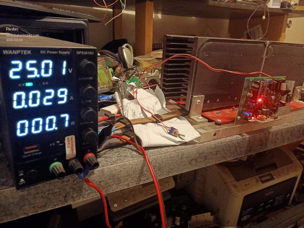 Tried powering up quickly to 31.5v and the green power light come on, obviously used a little more power (0.072a) before under voltage lockout and then the green power light went out. 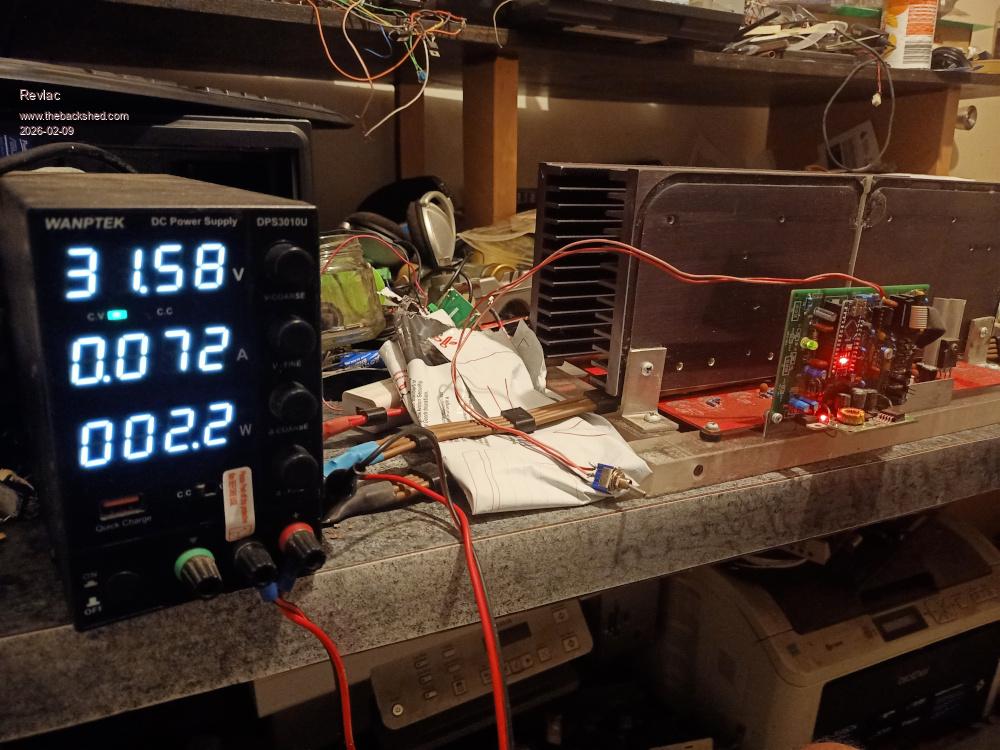 Your power consumption may be similar or higher. I will try to dig a little deeper to see were the problem short might be. Fault finding is a better terminology  Edited 2026-02-09 20:36 by Revlac Cheers Aaron Off The Grid |
||||
| Bryan1 Guru Joined: 22/02/2006 Location: AustraliaPosts: 2138 |
Well went thru my laptop last night trying to find the schematics for this project without luck as this project does go back over a couple of HD failures. Now I did get Roger to solder on the nano for the brainboard and he did go right over the board fixing some some of my dodgy soldering. Also the power board connections was done by Roger where he had a gander over the board and didn't see any problems. With that isolation paper I found on an old heatsink got 18 made so the hunt will be on for the last 2 pads so the back of the board can be isolated. Then I can have a look at the power board again with fresh eyes to see if there are any problems. Now after I isolated the front heatsinks I did split the 50 sqmm leads on VS1 and VS2 just to see if that was the issue where I used the lead on the front heatsink side but sadly that isn't the problem. Regards Bryan |
||||
| tinyt Guru Joined: 12/11/2017 Location: United StatesPosts: 561 |
Can you setup the brain board stand-alone so that it will output the four signals to the totem pole mosfet drivers? Then scope them for any anomalies. I think all you need is feed it with the expected filtered and level shifted DC converted from the 240vac of the inverter. Plus a start signal? |
||||
| Bryan1 Guru Joined: 22/02/2006 Location: AustraliaPosts: 2138 |
Ok setup my scope and I traced the pin position on blank pcbs. So channel 1 is VS2 high side Channel 2 is VS2 low side 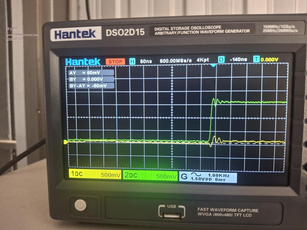 Now don't call me a scope expert but can take some time to get the screen set. Now I thought I was heavy handed in making the 10 pin cable as my ribbon thread is close to 20 years old and my method of using my jewelers vise to close the connection so I made another one and closed it gently and tried that but still no go. Now as I do have the scope setup any suggestions for other pins to trace would be welcome Edited 2026-02-10 12:24 by Bryan1 |
||||
| tinyt Guru Joined: 12/11/2017 Location: United StatesPosts: 561 |
I am just going by files in my archive and the testing direction from the EGs002 document. Experts here, please review my instructions. 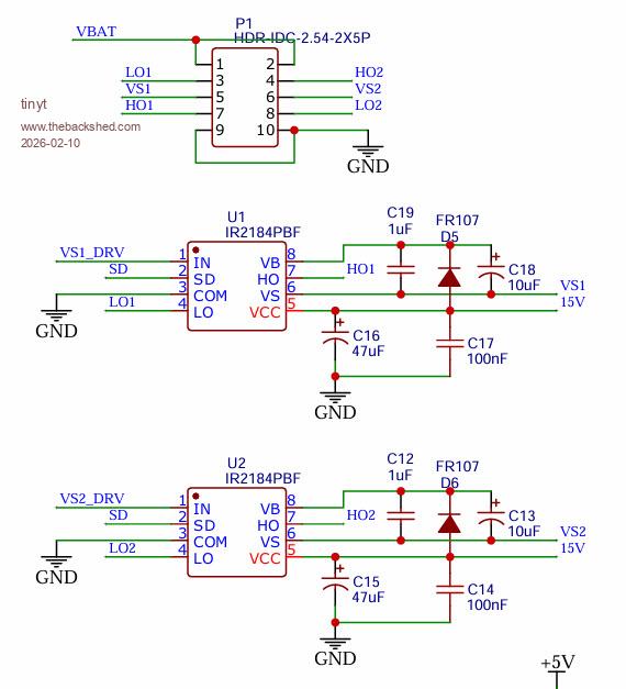 For stand alone testing, I think you temporarily connect VS1 and VS2 to GND. Scope Channel 1 and Channel 2 to DC, not AC. First scope capture: probe 1 to LO1, probe 2 to LO2. Set scope H to capture 1 to 3 cycles of 50Hz. Second scope capture: probe 1 to HO1, probe 2 to HO2. Set scope H to capture 1 to 3 cycles of 20KHz. Edited 2026-02-10 12:49 by tinyt |
||||
| tinyt Guru Joined: 12/11/2017 Location: United StatesPosts: 561 |
More scope captures: Third scope capture: probe 1 to LO1, probe 2 to HO1. Set scope H to capture 1 to 3 cycles of 50H. Position Base lines of CH1 and CH2 separate from each other to distinguish 0 volt of LO1 and LO2. Fourth scope capture: probe 1 to LO1, probe 2 to HO2. Set scope H to capture 1 to 3 cycles of 50H. Position Base lines of CH1 and CH2 separate from each other to distinguish 0 volt of LO1 and LO2. |
||||
| Bryan1 Guru Joined: 22/02/2006 Location: AustraliaPosts: 2138 |
Thanks for that TinyT gotta head into to town to feed my tummy bones and get a bit of a break from this inverter so this arvo I will setup those steps and see if I can learn and get the scope pic's.So one step at a time now thru my testing this morning the psu was sitting on 28 volts with 0.074 current, the resistor bank was cool to touch and no magic smoke was seen. Regards Bryan |
||||
| tinyt Guru Joined: 12/11/2017 Location: United StatesPosts: 561 |
Looking again at the partial schematic, check that the orientation of the two diodes are correct on the PCB, also the electrolytic capacitors. Also U1 and U2 if they are socketed. Maybe there is no need for the scope captures. |
||||
| Bryan1 Guru Joined: 22/02/2006 Location: AustraliaPosts: 2138 |
Ok got the first test done and found probe 1 L01 had a good wave form where probe 2 L02 was only in the millivolt range. So changed over to the 2nd test and after connection the probes to the wires saw the VBat drop to 10 volts so I think we found the problem as both probe waveforms were flat. Now taking the ground off restored VBat. So I'm goingto take out the brain board and have a good look as I do think that is where the problem is. First probe test 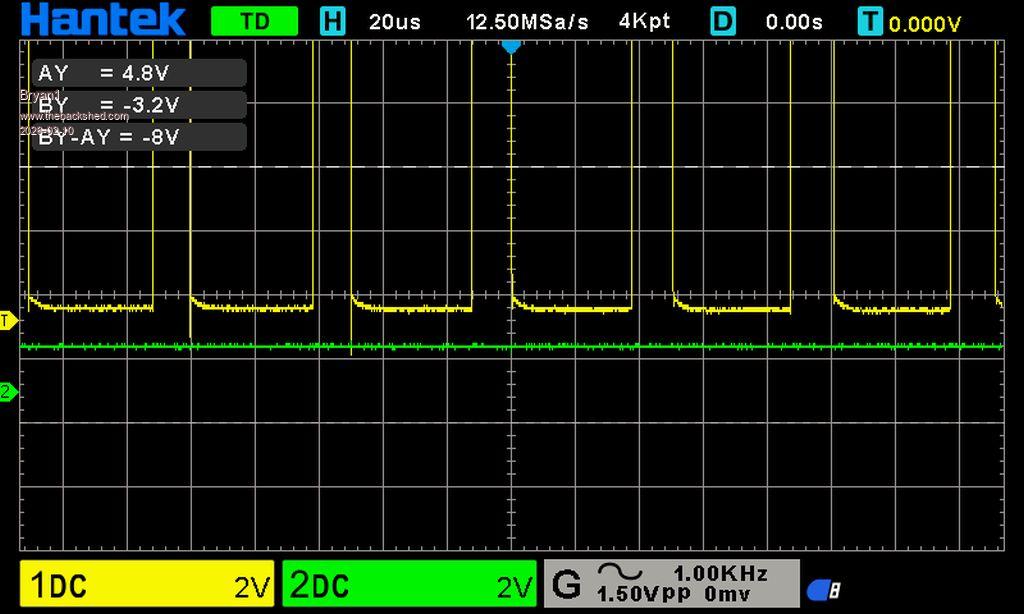 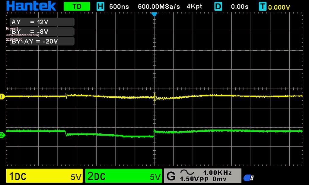 Regards Bryan |
||||
| Bryan1 Guru Joined: 22/02/2006 Location: AustraliaPosts: 2138 |
Ok got the brain board out and had a look 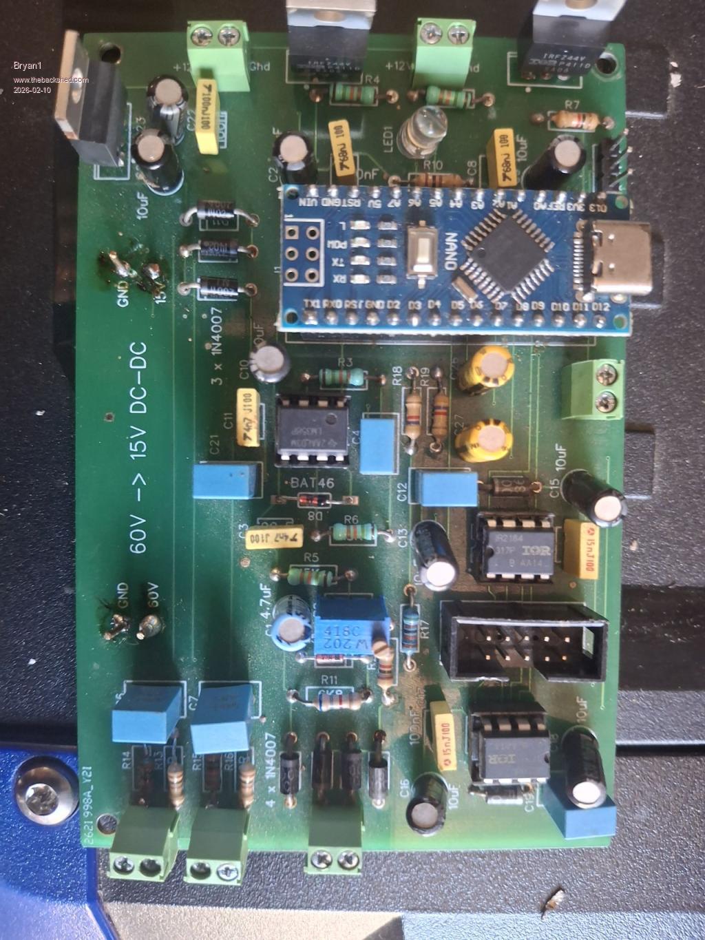 Now the fast diode on the end of the board fourth solder joint in the top right 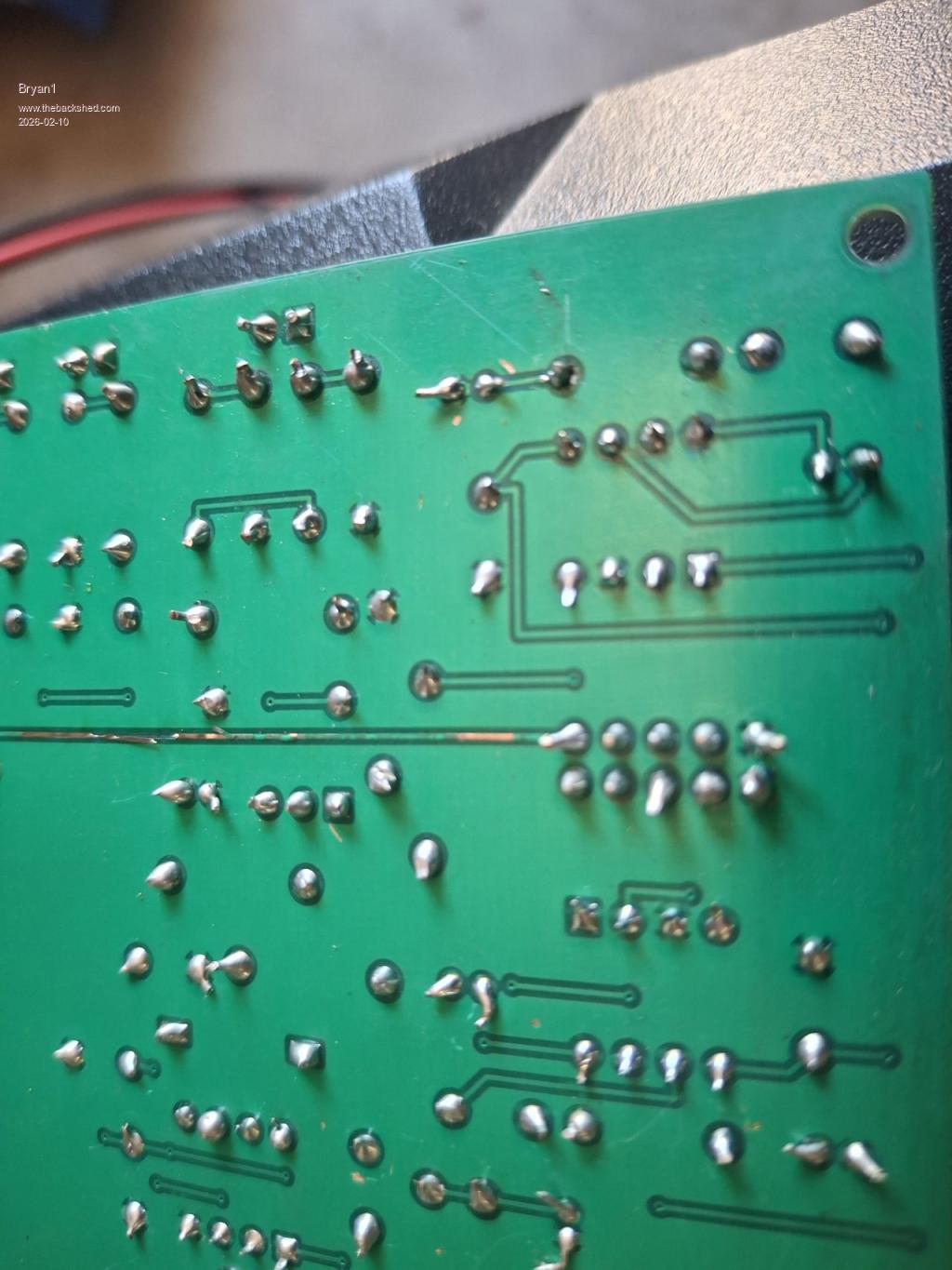 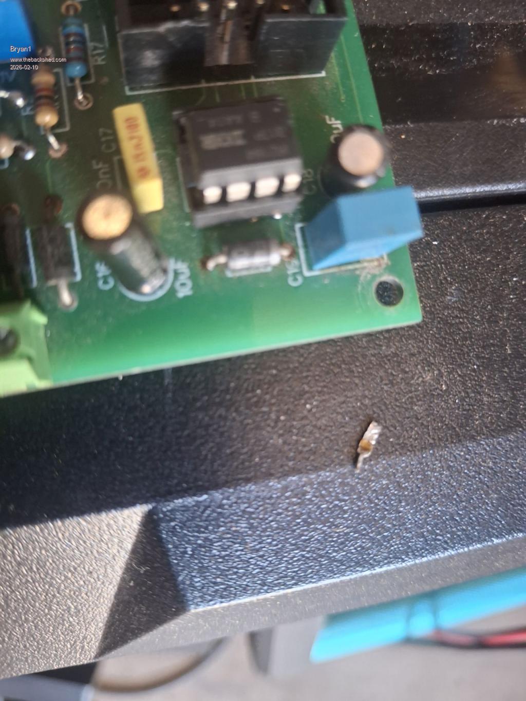 Now doing a diode test does show it isn't blown but that solder joint does need some attention. Just had a look under the board and this was staring at me 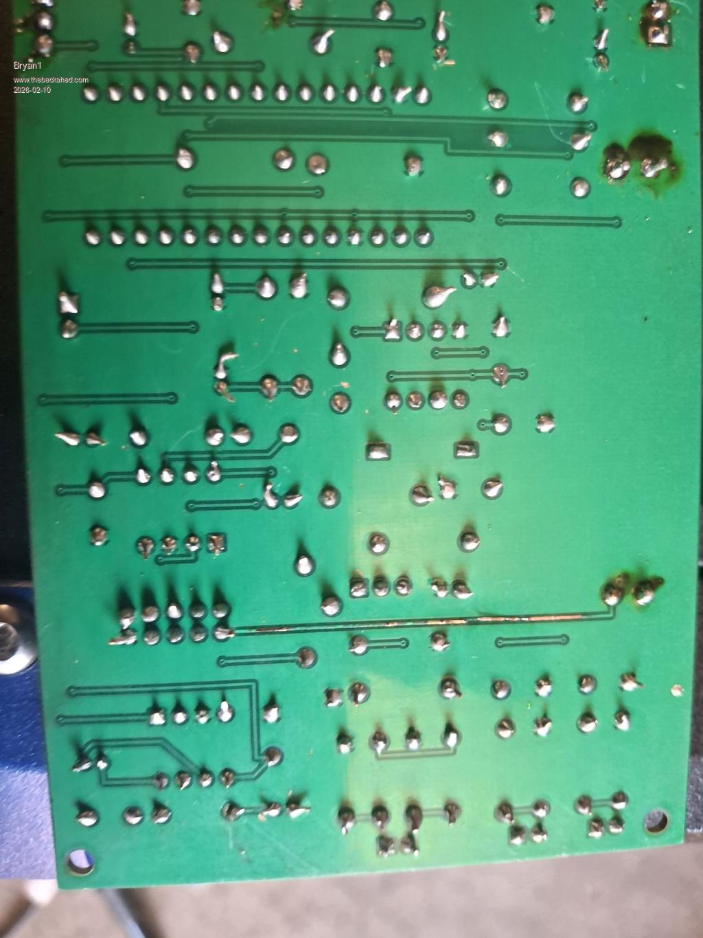 So the 50 volt track has lifted and this is the real culprit that I was looking for all along so the raised track could of been touching another component which caused the short. Edited 2026-02-10 15:40 by Bryan1 |
||||
| phil99 Guru Joined: 11/02/2018 Location: AustraliaPosts: 3317 |
The blown track in the middle of that pic. may need looking into as well! You need to find what caused that. Edit. Looks like it goes from the cable socket toward the 50V pin. Edited 2026-02-10 15:43 by phil99 |
||||
| phil99 Guru Joined: 11/02/2018 Location: AustraliaPosts: 3317 |
More likely a short caused the track to lift as it overheated. |
||||
| The Back Shed's forum code is written, and hosted, in Australia. | © JAQ Software 2026 |
