
|
|
Forum Index : Microcontroller and PC projects : PicoMite Alpha Firmware - a27 onwards - starting on displays
| Author | Message | ||||
| Mixtel90 Guru Joined: 05/10/2019 Location: United KingdomPosts: 8953 |
First - make sure you are using a reasonable quality USB lead and connect the Pico direct to the computer - not via a hub (unless it's mains powered). This is important as there is a bit of a surge in current at startup. If you followed the sequence of holding down the BOOTSEL button while powering up to get the dummy USB drive then the Pico is almost certainly running as the bootloader is on the chip. This *is* the cold system reset as it replaces all the data in the flash chip on the Pico. When you copy the (unzipped) uf2 file onto the dummy drive you should see the Windows bargraph as the file copies onto the Pico then the dummy drive should disappear. At this point just wait. There should be a few seconds delay then the green light on the Pico should start to flash. If that doesn't happen then it might be a good idea to download the file again (although it's unusual to get a corrupted file because they won't unzip) and start over. Repeated failures probably bean a bad Pico, unfortunately. If the green light starts flashing then you are halfway there. Don't unplug the Pico, we'll use the same Com port.. This works for me: Open Tera Term If you get an Error box just close it. Open Setup / Serial Port There should be a Com port showing. Ignore all the settings and click New open You *may* get a blank screen. Press the Enter key and you should see: > This is the MMBasic prompt. Press F4 to go to the editor, F1 to get back to this screen. You will need one of the manuals to go further. There isn't a specific PicoMite one yet, but the one for the ARMMite F4 is fairly close if read in conjunction with the doc files that I post on here. Update: PicoMite docs a48.zip Mick Zilog Inside! nascom.info for Nascom & Gemini Preliminary MMBasic docs & my PCB designs |
||||
| jaybek Newbie Joined: 25/05/2020 Location: GreenlandPosts: 18 |
I just recieved two Pi Pico's from a certified Raspberry Pi dealer in Denmark, I followed Volhout's 'Picomite doc a45.txt' and uploaded the a48 as described, and the Pico disappeared from the computer and noting else happened. The board was just dead, and the computer did not respond to any attempts to connect the board to it. That lead me on a major research, from which i will spare you the details. The file to reset the pico to factory settings is here: flash_nuke.zip What i have found is: On factory reset pico you cannot successfully on load a43-a48. The last version where you will get a heartbeat and a comport assignment is a42. With a a42 (or prior version) on board you can overwrite that and successfully update to a43-a48. Can anyone please replicate/confirm this? Regards Jens #MeTo ZX81 |
||||
| Glen0 Senior Member Joined: 12/10/2014 Location: New ZealandPosts: 101 |
You Backshedders are a determined lot, nice to see. @ Mixtel90, I have just now used a new PC and cable (win10 for what that's worth)and all according to your first 3 paragraphs. ( I see the Uf2 file being copied across according to the bar graph and for a brief moment the file appears in the "dummy drive" before it disappears) Dead after that and Tera term does not show any serial ports. I will get a fresh one out later and try again. At around NZ$6.90 a pop these are almost expendable. |
||||
TassyJim Guru Joined: 07/08/2011 Location: AustraliaPosts: 6543 |
Yes, I can confirm your observation. a48 directly onto a blank pico is no-go. Jim VK7JH MMedit |
||||
| lizby Guru Joined: 17/05/2016 Location: United StatesPosts: 3799 |
In case you didn't note the jaybek post, try flashing with a42 or earlier, then reflash with latest. ~ Edited 2021-07-07 09:30 by lizby PicoMite, Armmite F4, SensorKits, MMBasic Hardware, Games, etc. on FOTS |
||||
| Glen0 Senior Member Joined: 12/10/2014 Location: New ZealandPosts: 101 |
Good job. I flashed with a42 and got the blinkin light flashing. I then flashed with a48 and still had the blinkin light. Reflashed with a48 to be sure to be sure and hey presto, I could see the pico in Tera term. I will now go on to solder in some LED's (very low current of course) and see if I can make things happen. Cheers. |
||||
| Mixtel90 Guru Joined: 05/10/2019 Location: United KingdomPosts: 8953 |
Yay! :) Thanks jaybek. I'd completely forgotten about flash nuke. I downloaded it when I first got a Pico and used it once (can't remember why). It was a bit of a pig to find at the time because a link or two were dead. I'll add it to the PicoMite doc. Strange about having to load a42 first. This is something that probably wouldn't have been spotted because people were continually updating to the newer versions as they came out. It's something Peter will be interested in... (It's a Grrr! problem.) Edited 2021-07-07 16:39 by Mixtel90 Mick Zilog Inside! nascom.info for Nascom & Gemini Preliminary MMBasic docs & my PCB designs |
||||
| matherp Guru Joined: 11/12/2012 Location: United KingdomPosts: 11609 |
Won't have a chance to look at this for a few days so please include guidance in the PicoMite notes as to how to flash a new Pico thanks |
||||
| Mixtel90 Guru Joined: 05/10/2019 Location: United KingdomPosts: 8953 |
New initial install info added. Options list updated. PicoMite docs a48.zip . . Edited 2021-07-07 17:34 by Mixtel90 Mick Zilog Inside! nascom.info for Nascom & Gemini Preliminary MMBasic docs & my PCB designs |
||||
| lizby Guru Joined: 17/05/2016 Location: United StatesPosts: 3799 |
Depending on viewing environment, with newish LEDs, 10K resistors may work, 2K2 very likely. If you try different values, please report back. PicoMite, Armmite F4, SensorKits, MMBasic Hardware, Games, etc. on FOTS |
||||
jwettroth Regular Member Joined: 02/08/2011 Location: United StatesPosts: 86 |
I'm a huge fan of this port of MMBasic to the PICO. I have a system running with a little OLED and an RTC and am working to get good adc performance with a reference, etc- I have an analog background and can contribute on this. I was just starting to play with the PICO with Python since I received them recently- it all works nice but I prefer MMBasic. Python feels a bit heavy- importing big libraries and using OOP techniques to do simple things. Arduino has gone in a similar OOP direction with their adoption of C++. I don't see the utility really. MMBasic seems like a very nice fit for the PICO. I have a few questions- excuse me if this has been covered but I can't find the answers after reading though a couple of big threads and the notes on the "Fruit of the Shed". QUESTIONS 1. The PICO is a dual core CPU- does MMBasic make use of both cores or allow spawning off a process on the second core? Could MMBasic be ported in such a way to make use of both cores? Could the second core be dedicated to servicing interrupts for example? 2. The PIO functionality of the PICO is awesome. I can see some great applications for this- one that I'm going to look at soon is fast quadrature decoding, keeping up with CNC shaft encoders in real time in the background. I played with this in Python a little and have some familiarity. I see that there has been some work and a proof of concept of running these little programs. How does MMBasic make use and access the FIFO's to push and pull data from the CPU's? Thanks very much to Peter, Geoff and the beta testers here for all the amazing work. If I find anything worth reporting, I'll be sure to share but I'm afraid I'm in catch-up mode so far. Thanks in advance. Regards, John M. Wettroth John Wettroth |
||||
| Mixtel90 Guru Joined: 05/10/2019 Location: United KingdomPosts: 8953 |
ANSWERS :) 1. matherp tells us that because of the way MMBasic works it wouldn't easily convert to dual core systems. IMHO it's highly unlikely that processes could be spawned off. However, my personal feeling is that it's *possible* that if/when a bigger (more memory) version of the RP2040 should appear then a second core might handle video. At the moment memory is too tight to do that. You *can* get VGA out of a Pico, but not leaving space for much else. 2. Do you mean access to the state machines? PIO READ pio, state_machine, count, data%() gets data from a state machine and PIO WRITE pio, state_machine, count, data0 [,data1....] writes data to one. Hopefully I'll have an assembler ready soon, taking instructions in the form of DATA statements and producing PIO program code in an array. Mick Zilog Inside! nascom.info for Nascom & Gemini Preliminary MMBasic docs & my PCB designs |
||||
| Volhout Guru Joined: 05/03/2018 Location: NetherlandsPosts: 5981 |
on revision a48: I did a port of the Huntron Tracker (MX170 Backpack tracer) to the picomite, and in essence it works. It's speed is about 1.6 times faster than the MX170. The main loop consists of LCD writes, ADC reads, PWM changes and a little math. There is however a performance difference in the displayed trace on the LCD. This can be caused by ADC performance, reference voltage (power supply ripple), PWM settling (does the PWM react immediately after writing), or math errors. I noticed that OPTION POWER PWM / PFM causes a restart of the board, and that intrigues me. Since the option does not show in OPTION LIST I thought it was not persistent. But is essence it is simply toggling one PIO line, that should not cause any interrupt of the power system. This evening I will try to analyze a bit further. Maybe the PWM filter causes the problem (tuned for the latency of the MX170). Volhout PicomiteVGA PETSCII ROBOTS |
||||
| Mixtel90 Guru Joined: 05/10/2019 Location: United KingdomPosts: 8953 |
Changing the power system between PFM and PWM changes the way that the SMPS operates. I don't know how that works (yet - it's an input to the switcher IC), but it *may* involve a shutdown while the switcher changes mode - especially if switching at low current. At low currents the default is PFM as that is most efficient (but rather noisy) but it does change to PWM as the load current rises. Switching over at low currents might be the problem. PWM is a bit less "noisy" so if you are doing much with the ADC that might be better. Also, you can just stick a 3V reference regulator between VREF and GND to get a much better (but 3V) reference. The current is limited to 1.5mA through it. If noise is still bad, do what Peter did - ground 3V3EN and connect a LDO linear reg from 5V to 3.3v. That will get rid of the supply switching noise. Don't attempt this if you are connecting to the PicoMite over USB though. Edited 2021-07-09 00:54 by Mixtel90 Mick Zilog Inside! nascom.info for Nascom & Gemini Preliminary MMBasic docs & my PCB designs |
||||
| Volhout Guru Joined: 05/03/2018 Location: NetherlandsPosts: 5981 |
The RT6150 used on the pi pico is a buck-boost converter. And over the input voltage range it changes modes. At low power (100mA) that causes output voltage changes: see below. Especially interesting is the changeover around 5V input voltage. That is exactly where it is used on the pico. I think I will look for a linear -or- add a 3V reference. 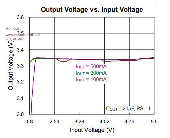 PicomiteVGA PETSCII ROBOTS |
||||
| Mixtel90 Guru Joined: 05/10/2019 Location: United KingdomPosts: 8953 |
I got a LM4040-3V 0.5% reference for a power supply. Pretty cheap at 90p in the UK. LM4040C30ILPR or NFC30I I looked at your backpack tracer and at the PicoMite and at the little 240x240 IPS display I've been playing with and wondered about a pocket version... :) The SMPS would let it run from a couple of AAA cells. Mick Zilog Inside! nascom.info for Nascom & Gemini Preliminary MMBasic docs & my PCB designs |
||||
| Volhout Guru Joined: 05/03/2018 Location: NetherlandsPosts: 5981 |
@Mixtel90: the backpack schematics show a converter from 5V that outputs +/-17v at 10mA. That convertor is tested down to 4.5V...5.5V, but I am not sure it will run and deliver sufficient power from 4V or 3.5V... PicomiteVGA PETSCII ROBOTS |
||||
| Mixtel90 Guru Joined: 05/10/2019 Location: United KingdomPosts: 8953 |
I must admit that I don't know much about these trackers/tracers/whatever. Your project is the first time I've heard of the official versions. I think I saw a similar thing using a transformer many years ago, but that's all. :) I see that at least some of the earlier trackers only give a current limited 1v at the probe to protect sensitive components. As, if you use a 3v reference, you can only accept an absolute max of (biased) +/- 1.5v into the ADC anyway why use such a high voltage? Modern op-amps can easily get within 0.5v of the supply rails at low current output. Just an idea... Would it be possible to just generate -3.3v from the Pico output (using a diode pump from a (buffered?) PWM output) and work with +/- 3.3v for the op amp and level shift to get 0-3v into the ADC? Mick Zilog Inside! nascom.info for Nascom & Gemini Preliminary MMBasic docs & my PCB designs |
||||
| Volhout Guru Joined: 05/03/2018 Location: NetherlandsPosts: 5981 |
Hi Mixtel90, First of all, i found the problem with the distortion of the trace. The pwm filter had a component with wrong value. The picomite in default config after reboot works adequate for this application. No linear regulator needed. About the voltage range, yes, you could lower it. But mind that if you want to probe a 3.3v circuit for a defective esd diode you need at least 4v at the probe tip, add the voltage over the measurement resistor, and some headroom for the amplifier, you easilly need +/- 6volt power rail. My design can also check 5v circuits, and even measure zener diodes up to 12v. Again, those where.my design goals, yours could differ.... Anyway, a low voltage design is definitely possible. The software only needs adaptation in a few constants. The hardware change is also simple. As to answer your question on the -3.3v. I am not sure if that will work with the buck boost in pfm mode. In pwm it will, only you get -5v.... not -3.3v.... P.s. Check the schematics, the pwm is amplified and level shifted. The ADC input is also pre-biassed to centre the input voltage around mid 3.3 v Edited 2021-07-10 03:48 by Volhout PicomiteVGA PETSCII ROBOTS |
||||
| Mixtel90 Guru Joined: 05/10/2019 Location: United KingdomPosts: 8953 |
Thanks - I'll have another look at your circuit. My thoughts about the probe voltage were because I read that the low voltage ones could be used to test the pins on 74 series logic - in fact, just about anything, because there was no chance of over-volting anything. True, an LV model wouldn't test zeners. Mick Zilog Inside! nascom.info for Nascom & Gemini Preliminary MMBasic docs & my PCB designs |
||||
| The Back Shed's forum code is written, and hosted, in Australia. | © JAQ Software 2026 |
