
|
|
Forum Index : Microcontroller and PC projects : Colour Maximite 2 Deluxe Edition with USB mouse support
| Author | Message | ||||
| elk1984 Senior Member Joined: 11/07/2020 Location: United KingdomPosts: 232 |
Possibly the only thing better would be a bolt on to the back where cartridges can be fitted & swapped 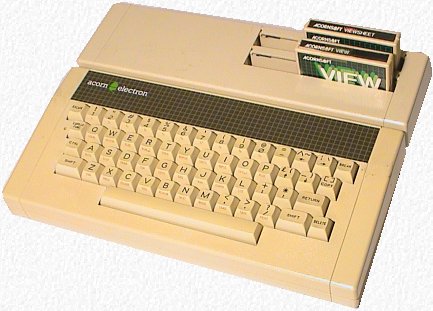 But that is definitely my Acorn Electron heritage showing  By the way - loving the CMM2 Deluxe - all working like a charm and the signal to my capture card is razor sharp. |
||||
| Paul_L Guru Joined: 03/03/2016 Location: United StatesPosts: 769 |
I definitely know where Poland is. I worked for PanAm engineering for a third of a century. I've been almost everywhere in the world. Vladimir, my grandfather, came from Balice, near where the Krakow airport is now, and was considerably closer to Krakow than you are. Edge connectors are used extensively in Boeing aircraft, particularly in the Delco INS computers and the digital Bendix autopilot computers. They are extremely reliable and are relatively easy to clean. I don't like the individual pins and sockets which are so prominent today in the piggyback boards. I see that you are trying to control a bunch of small motors. Inrush currents are a problem when starting ac motors, even very small ones. Switching on a TRIAC for a successively increasing duty cycle during each half cycle is the best way to accelerate the motor. It should be simple to control the successively changing trigger points programmatically. After a few seconds you could pull in a mechanical relay which would bypass the TRIAC and eliminate it's continuous voltage drop and self heating while the motor is running. Stopping the motor would entail simply dropping out the mechanical relay after which the TRIAC would block at the next zero crossing point. This should eliminate any arcing of the mechanical contacts on shutdown. You are doing very good work! Make sure that you bypass RFI and transients, especially if there are motors involved, with lots of small caps, and make sure that the female edge connector sockets are accessible for cleaning. Pavel Artur Jan Waclaw Lepkowski in New York Edited 2020-11-07 02:51 by Paul_L |
||||
mclout999 Guru Joined: 05/07/2020 Location: United StatesPosts: 510 |
If I am correct when do I get my board?? They call me Shai-Hulud (The maker) |
||||
| siwypiotr Senior Member Joined: 18/08/2020 Location: PolandPosts: 127 |
Ok ok, You are correct. If You want the board now in current state of development I can print 3d model on paper and send to You :P or You can wait when it is done? |
||||
| mclout999 Guru Joined: 05/07/2020 Location: United StatesPosts: 510 |
I will wait and thank you. Have a great day. They call me Shai-Hulud (The maker) |
||||
| siwypiotr Senior Member Joined: 18/08/2020 Location: PolandPosts: 127 |
Oooo I did not know it so it looks like You will like it also. In fact Im not planning to control anything, Im making those card for other people to find use for it. Im not sure for what customers will use it, they can use it for AC or DC, that is why Im not sure if I should add any arcing suppression (due to inductive nature of controlled device) or zero crossing circuit (I do not know how to build it so it works for both AC and DC usages) |
||||
| siwypiotr Senior Member Joined: 18/08/2020 Location: PolandPosts: 127 |
Bolted solution is nice, unfortunately it can not me done on existing original units :( Nice that You like the picture, correct layout of VGA lines took me way too long, I had to scrap a lot of test batches and lost a lot of money because I was not too happy about with previous designs. |
||||
| Paul_L Guru Joined: 03/03/2016 Location: United StatesPosts: 769 |
Piotr, Inrush current limitation for dc motors is usually not critical. A dc motor is a torque producing device. Its acceleration characteristics are determined by the lap and plex of its winding pattern. It a bunch of relays are intended to control motors it is likely that they will be ac motors ... dc motors are extremely rare since Edison got out of the business of electrifying railroads. They still do exist in diesel electric locomotives. If you're starting a bunch of motors (presumably ac) you have to either use mechanical relays heavy enough to carry the locked rotor current or find some way to limit the locked rotor current. As relay size increases the response speed lengthens, the life expectancy decreases and the cost increases, all exponentially. The overall design would probably be cheaper to build if you use a TRIAC gated on at a variable time during the sineusoid to start the motor, then a smaller mechanical relay in parallel to provide the continuous running current, then allow the TRIAC to disconnect the circuit when the current goes to zero. The cost of a (TRIAC + smaller relay + timing components) might be less than the cost of a bigger relay. Circuits like this are found in "soft starters" for refrigeration compressors which reduce the starting current to 20% of the normal starting current. They are sometimes the only way to start a big compressor on a small local generator. They are usually priced way above the parts cost of the gadget. http://www.hypereng.com/ https://www.micro-air.com/ Just something to think about. Pavel in NY |
||||
| Tinine Guru Joined: 30/03/2016 Location: United KingdomPosts: 1646 |
Yes, I had the 8266 on a MX170 module which had power issues and a large capacitor solved the problem.  |
||||
| markboston36 Regular Member Joined: 27/10/2020 Location: United StatesPosts: 76 |
if only i found this thread before i bought my CMM2. i don't really need any of the enhanced features except for the joystick port that would be nice. i would just want to make sure you keep creating great things. your expansion boards are intriguing and i will definitely be buying those. keep us posted here on the progress. im sure it was mentioned somewhere here but what is your website? im polish decent so its good to see a fellow countryman doing great work! |
||||
| JohnS Guru Joined: 18/11/2011 Location: United KingdomPosts: 4352 |
Is polish decent the same as decent Polish? Just joshing - welcome! John |
||||
| lizby Guru Joined: 17/05/2016 Location: United StatesPosts: 3811 |
Maybe it's Reverse Polish. Still joshing - welcome! PicoMite, Armmite F4, SensorKits, MMBasic Hardware, Games, etc. on FOTS |
||||
| markboston36 Regular Member Joined: 27/10/2020 Location: United StatesPosts: 76 |
both of you are real comedians  |
||||
| siwypiotr Senior Member Joined: 18/08/2020 Location: PolandPosts: 127 |
Sorry for late replay I have been busy building latest version of Maximite Deluxe with build in WiFi support. Im happy to announce that it is working without any problems. Thanks to power line filtering next to the module there is no power drop issues: https://youtu.be/NcFPdyanlXw My web page is: https://sklep.pslabs.pl/Elektronika-c86/s_lang/en From Tuesday I will start shipping units with WiFi. |
||||
| siwypiotr Senior Member Joined: 18/08/2020 Location: PolandPosts: 127 |
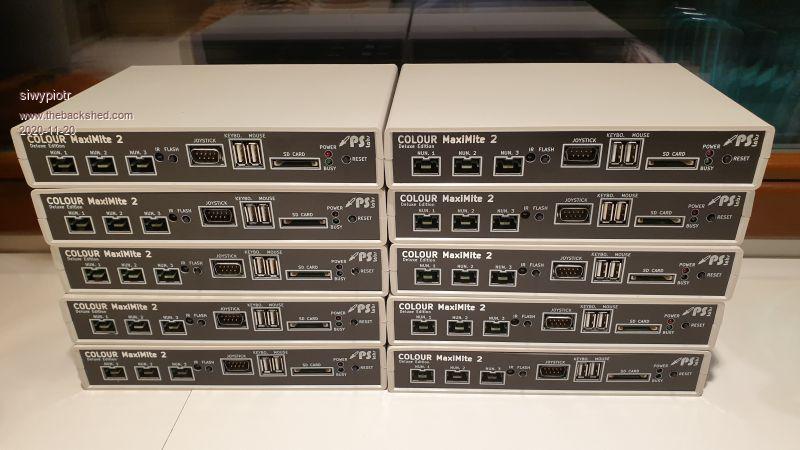 It is possible that this is the last batch of Maximite that I made. All of them I will ship with random gifts like (apart of SD card, USB cable, ESP WiFi, Mouse controller): VGA to HDMI converter NES controller Nunchuk controller VGA cable � � � https://sklep.pslabs.pl/Colour-Maximite-2-Deluxe-Edition-USB-Host-Contr-WiFi-p150?fbclid=IwAR15PxVSOcWdjtZHok9MINe03HlfI_iPvYUit7yYpl21YGtD8aicQkRIxEU Since many people asked the question i would like to make small update. It is not that I scrap the project, design is finished and there is nothing that I can change to make it better. The project is and will be supported now and in the future. I need some time to develop other products like expansion system for Maximite and some gadgets for Atari ST. It is also possible that if I will find some time I will make another batch but to do that I would like to hear from everyone if they are interested. Edited 2020-11-21 23:35 by siwypiotr |
||||
| siwypiotr Senior Member Joined: 18/08/2020 Location: PolandPosts: 127 |
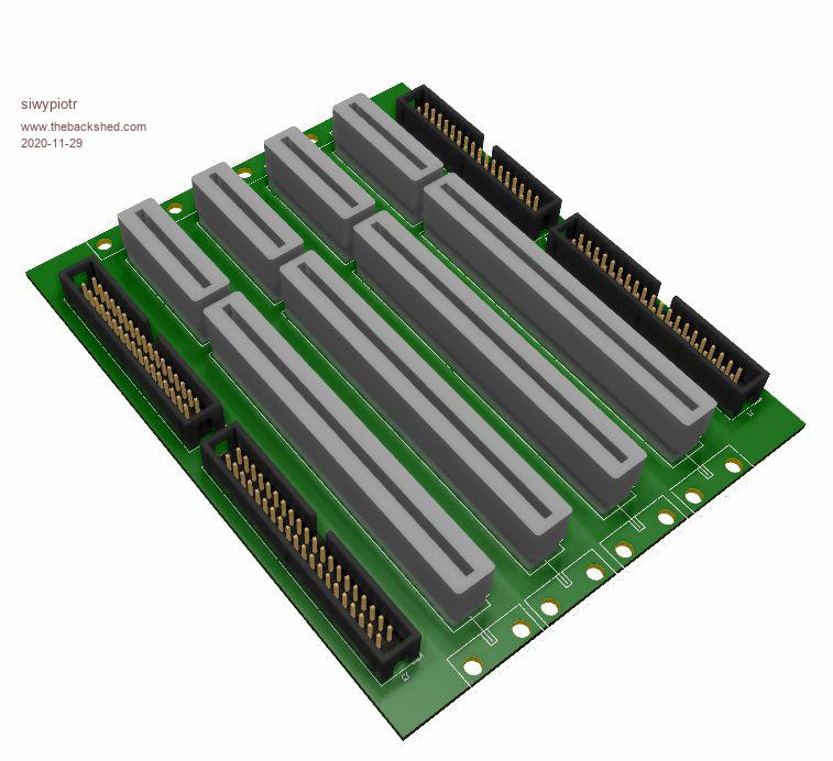 Hi I finally found little time to continue on my expansion system for maximite. I would like to make it in size of standard Maximite 2, so it sits nicely on top of the unit. I do not own original Maximite 2, could someone please measure original box size? is it 139,5mm / 110 mm ? Thank You for help. |
||||
| romba6 Newbie Joined: 04/07/2020 Location: United KingdomPosts: 37 |
My top cover is 139mm, this includes the small radius. The 'flat' part is 132mm. the other dimension is correct. Edited 2020-11-29 01:07 by romba6 |
||||
| elk1984 Senior Member Joined: 11/07/2020 Location: United KingdomPosts: 232 |
Mine is W: 140mm x D: 110mm x H: 35mm Again mine has a slight curvature on the top / sides. |
||||
| siwypiotr Senior Member Joined: 18/08/2020 Location: PolandPosts: 127 |
Thank You for help, Is it possible that cover that producer used is similar to this? 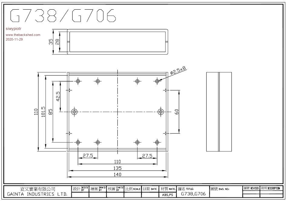 If Yes that would be nice because i want to use (one of the half) as enclosure and it will sit perfect on the top of maximite. Edited 2020-11-29 01:23 by siwypiotr |
||||
| toml_12953 Guru Joined: 13/02/2015 Location: United StatesPosts: 685 |
Are any more of these going to be available? |
||||
| The Back Shed's forum code is written, and hosted, in Australia. | © JAQ Software 2026 |
