
|
|
Forum Index : Microcontroller and PC projects : PicoMite Alpha Firmware - a27 onwards - starting on displays
| Author | Message | ||||
| lizby Guru Joined: 17/05/2016 Location: United StatesPosts: 3783 |
Control of LEDs on PicoMite using HTML Running on a28 but not using any of its new features. This uses the LEDs I posted about previously. Pins 1 and 2 are used by an ESP-01, which provides the wifi. Again thanks to Peter Mather not only for all the work on Armmite, CMM2, PicoMite, but also for the framework for handling the html. I made a little perfboard for the ESP-01 with an LD33 regulator to drop down the 5V. I soldered female headers for the perfboard male headers directly to the castellated parts of pins 1-3 and 38-40 (not using 38 & 39, just soldered to them to increase strength).  Here's what the HTML page looks like:  Unusable pins are grayed out. Checked pins are lit, unchecked are not. I didn't attempt to match the colors on the HTML form to the colors of the actual LED, though it would not be hard to do that. I used white as the color of an unlit LED. After you check or uncheck one or more pins, clicking [Submit] submits the form, and the leds are updated almost immediately. It takes a few seconds for the PicoMite to render the HTML page. Here's a 2-minute youtube video: htmlLEDs on PicoMite And the program: htmlLEDs.zip ~ Edited 2021-06-21 23:45 by lizby PicoMite, Armmite F4, SensorKits, MMBasic Hardware, Games, etc. on FOTS |
||||
| lizby Guru Joined: 17/05/2016 Location: United StatesPosts: 3783 |
Success with ILI9341 ... But only partial. > option list OPTION SDCARD GP5, 10 OPTION SYSTEM SPI GP2,GP3,GP4 OPTION LCDPANEL ILI9341, LANDSCAPE, 26, 25, 24 For the LED pin on the ILI9341, I used a 47R resistor, 3V3 to LED pin. >  (The jaggies in the circles are a camera artifact.) With this code: ' circles.bas q to quit ' font 1 Dim integer i Do x=Rnd*MM.HRes y=Rnd*MM.VRes c=Rnd*&hFFFFFF ' and &HF8FCF8 r=Rnd*50+10 Circle x,y,r,,,c,c a$=Inkey$ If a$="q" Or a$="Q" Then Print a$+" Exiting": Exit i=i+1 Print i;" "; Pause 100 Loop The circles run through about 50 iterations--then the screen goes white. The counter continues to increment. Ctrl+C returns to the prompt, but running the program again results in white screen from the beginning and count incrementing. Power cycling allows you to run the program and show the circles again through about 50 iterations. ~ Edited 2021-06-22 01:20 by lizby PicoMite, Armmite F4, SensorKits, MMBasic Hardware, Games, etc. on FOTS |
||||
| lizby Guru Joined: 17/05/2016 Location: United StatesPosts: 3783 |
Similar with ILI9488 with the same code, except that non-camera artifacts appear around iteration 50, and the screen doesn't go white until about 100 iterations.  PicoMite, Armmite F4, SensorKits, MMBasic Hardware, Games, etc. on FOTS |
||||
| matherp Guru Joined: 11/12/2012 Location: United KingdomPosts: 11500 |
Lizby, please try this version a30 PicomiteV5.07.00a30.zip I didn't get your issue but saw a different corruption. Unfortunately I think the problem is electrical. Please try running your test with and without an SDcard inserted. If you get the problem stop the program and type the command TEST then run it again - what happens? I suspect the RP2040 pin drive is poor and the SPI data is getting misread which causes the LCD to change configuration |
||||
| Volhout Guru Joined: 05/03/2018 Location: NetherlandsPosts: 5931 |
If it is a pin drive issue you van make it worse bij adding load. Touch clock or data pin with a patch wire tou are holding. The e tra himan body connected will reveal the pin drive problem. PicomiteVGA PETSCII ROBOTS |
||||
| matherp Guru Joined: 11/12/2012 Location: United KingdomPosts: 11500 |
Tom Please try your SDcard on the Maker board with this version I've found a way to increase the drive current on the SPI pins which may make a difference Lizby May also solve your issue - does for me. You may also need a second power source to the Backlight LED pin a31 PicomiteV5.07.00a31.zip Edited 2021-06-22 02:30 by matherp |
||||
CircuitGizmos Guru Joined: 08/09/2011 Location: United StatesPosts: 1427 |
That's a cool effect! Micromites and Maximites! - Beginning Maximite |
||||
| Mixtel90 Guru Joined: 05/10/2019 Location: United KingdomPosts: 8909 |
AFAIK that's right. It would make sense. @matherp Using a29 I2C0 is working fine now, thanks. :) Mick Zilog Inside! nascom.info for Nascom & Gemini Preliminary MMBasic docs & my PCB designs |
||||
| lizby Guru Joined: 17/05/2016 Location: United StatesPosts: 3783 |
The circles program works on a31 for both the ILI9341 and ILI9488--over 500 iterations on each before exiting with Ctrl+C. I did swap a 68R resistor for a 47R on the LED pin, so a third less draw. Still bright enough for my uses. PicoMite, Armmite F4, SensorKits, MMBasic Hardware, Games, etc. on FOTS |
||||
| thwill Guru Joined: 16/09/2019 Location: United KingdomPosts: 4369 |
Sorry Peter, it went back in the post 5 hours ago. If it comes back with a "No fault found" sticker then I will certainly give it a try. Best wishes, Tom MMBasic for Linux, Game*Mite, CMM2 Welcome Tape, Creaky old text adventures |
||||
| matherp Guru Joined: 11/12/2012 Location: United KingdomPosts: 11500 |
a32 PicomiteV5.07.00a32.zip 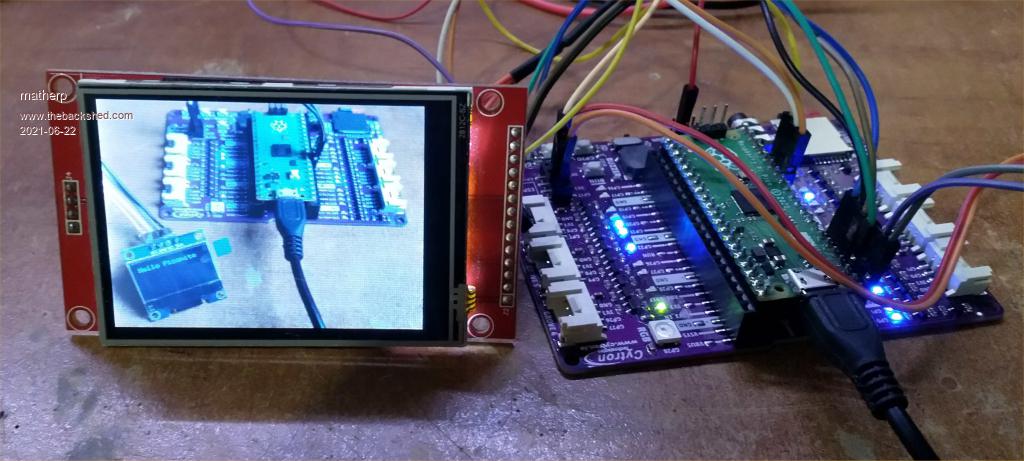 Load and save image now working NB: save image only for ILI9341 BLIT and transparent text also working for ILI9341 ARC implemented - untested Edited 2021-06-22 07:51 by matherp |
||||
goc30 Guru Joined: 12/04/2017 Location: FrancePosts: 435 |
SD Card: I have same problem as Tom with new version (a26 to a32) "file" function say "Error : There is no valid FAT volume" if I put my sdcard used on CMM2, it is ok with a25 version, all is ok. it can read and write 2 sdcards are same (scandisk). There is only 1 difference: cmm2 card is an 16g0 pico card is an 32go (why it work with v.a25??) |
||||
| lizby Guru Joined: 17/05/2016 Location: United StatesPosts: 3783 |
I have an "Error : SD Card not found" issue since I hooked up the SPI LCD. If I remove the LCD, "Files" works. If it's plugged in, it doesn't. > option list OPTION SDCARD GP5, 10 OPTION SYSTEM SPI GP2,GP3,GP4 OPTION LCDPANEL ILI9341, LANDSCAPE, 26, 25, 24 > This happens even if OPTION LCDPANEL has not been set. PicoMite, Armmite F4, SensorKits, MMBasic Hardware, Games, etc. on FOTS |
||||
| matherp Guru Joined: 11/12/2012 Location: United KingdomPosts: 11500 |
In a25 and below the SDcard SPI was bitbanged using standard digital I/O. Above a25 the firmware uses the H/W SPI. You can set the SPI speed using the optional parameter on the command OPTION SDCARD CSpin [,speed in MHz] In all versions the card initialisation is bitbanged as H/W SPI won't run slowly enough. If you, for example, set OPTION SDCARD CSpin, 4 then the H/W SPI will be running much more slowly than the bitbanged version. However, You collectively are reporting issues and these get even worse when an LCD is also attached to the SPI pins. The problem seems to be electrical rather than software. So, for example, I was seeing corruption in the LCD with the SDcard inserted but not with it removed but still configured. Personally I don't see any issues at all with the SDcard. I can now run reliably with the LCD and SDcard since I included an instruction to increase the pin drive level although I can't confirm this has effect when the pins are configured for SPI. I also power the LCD backlight with a separate supply from the USB I'm using the Maker board as pictured above for development. Things to check: Use a SDcard socket without any pullups as these will add to load on the SDpins further and are not needed for SPI access. Keep wires short and tidy Add a 10uF capacitor across the power pins of the SDcard Do not use pins GP18-GP22 if using a Maker PCB Don't power the Picomite from a laptop or other "weak" USB source, If necessary use a powered hub If connecting an LCD as well as a SDcard make sure the TOUCH CS pin is tied HIGH - VERY IMPORTANT: If using a ILI9488 display DO NOT CONNECT THE MISO PIN this will kill everything Overall this does seem to suggest that the RP2040 I/O system is somewhat marginal compared to the likes of the STM32 or PIC32 and this is evidenced by the very low maximum chip drive capability (12mA per pin and 50mA total vs 20mA per pin and 150mA total for STM32). Also, it is clear some SDcards are either more power hungry or noisier than others. A solution is to dedicate pins to the SDcard but this is very wasteful with the already limited I/O on the RP2040. Tom has reported that his SDcard now works when he stopped using the Maker board so it is clear the H/W environment is critical. Please try the steps outlined above and let me know findings Edited 2021-06-22 17:56 by matherp |
||||
| Volhout Guru Joined: 05/03/2018 Location: NetherlandsPosts: 5931 |
Would it be an idea to use system SPI for the displays and touch, that leaves a second SPI free for application use. And keep the SD card on bitbang mode ? That way you can move the SD card pins around as required, and most people seemed happy with the performance in bitbang mode. My personal fear is that the bus load (SPI bus load) by adding LCD, SDcard and Touch to one SPI impacts the rise time and fall time of the data and clock signals. Maybe the logic inside the RP2040 is critical for settling time or hold time. And these get compromised by to much bus load. Most ILI9341 have an SD card reader, but these are at different pins anyway (different connector even). PicomiteVGA PETSCII ROBOTS |
||||
| Mixtel90 Guru Joined: 05/10/2019 Location: United KingdomPosts: 8909 |
I wouldn't have thought the SD cards would be loading the supply too much. The 3.3v supply from the SMPS is rated for 300mA and the data/clock pins are very little load. A bypass cap on the SD card power pins is a good idea. Either a 10uF ceramic or a 10uF electrolytic + 0.1uF ceramic in parallel. You do need a good 5V supply for the Pico though. I've noticed that my "baby" computer doesn't want to boot up if I have the PicoMite plugged in so there must be a switch-on surge. It's a similar problem to the CMM2 - don't use wet-string power leads and saggy power supplies. Completely unconnected with the above - I see that Farnell's price for a PIC32MX170 is 4.86UKP inc. vat - about 1.20UKP *more* than a bare Pico ... Mick Zilog Inside! nascom.info for Nascom & Gemini Preliminary MMBasic docs & my PCB designs |
||||
| matherp Guru Joined: 11/12/2012 Location: United KingdomPosts: 11500 |
They seem to have a big current draw at some times that is why all my H/W designs power them through a 2R2 resistor with a 10UF and 0.1uF capacitor across the SDcard power pins |
||||
| thwill Guru Joined: 16/09/2019 Location: United KingdomPosts: 4369 |
The SD card adapter that worked for me (at least superficially, I haven't really tried hammering this thing yet) was one of these: 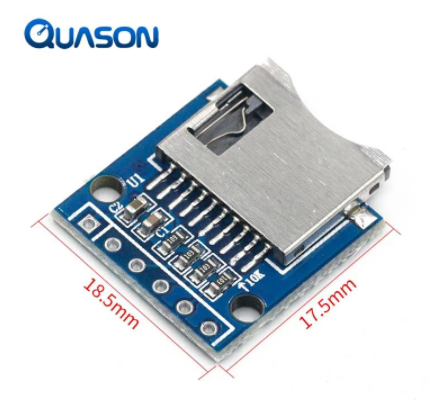 I can see that it has resistors and a couple of capacitors, are the former the pullups we don't need ? - remember I really am "monkey see, monkey do" in my electronics at the moment. I may have just been "lucky" in my choice, because I now see that there seem to be a dozen variations some with just passive components (like this one) and others with transistors (I think) and/or ICs. I don't suppose anyone can point me at a beginners reference to explain this variety ? Best wishes, Tom MMBasic for Linux, Game*Mite, CMM2 Welcome Tape, Creaky old text adventures |
||||
| matherp Guru Joined: 11/12/2012 Location: United KingdomPosts: 11500 |
You have pullups but they look like 10K so almost no load and not worth bothering about. The capacitors are GOOD |
||||
| goc30 Guru Joined: 12/04/2017 Location: FrancePosts: 435 |
Hi pete thank for your response in this case I use maker board without lcd (nothing on spi exepct sdcard) I have test some options with a32 result: > option sdcard disable > option sdcard gp15,4 > files Error : There is no valid FAT volume > option sdcard disable > option sdcard gp15,1 > files Error : There is no valid FAT volume > option sdcard disable > option sdcard gp15 > files Error : There is no valid FAT volume |
||||
| The Back Shed's forum code is written, and hosted, in Australia. | © JAQ Software 2026 |
