
|
|
Forum Index : Microcontroller and PC projects : Micromite eXtreme: The PCB portfolio
| Author | Message | ||||
| Phil23 Guru Joined: 27/03/2016 Location: AustraliaPosts: 1667 |
I've used a 300mm IDE cable on an E64. Worked fine except when I had issues with the breadboard & DuPont connectors. On the topic of cables, does anyone recall these; just had a ferret about to find one. 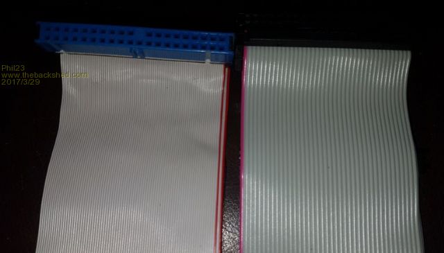 They were a higher spec IDE cable with 80 conductors instead of 40, but still 40 pin. Maybe they would be more suitable than the standard ide. Don't recall how the 80 cores were wired, but someone might know. Not also it has a key pin, would need to drill a hole to accommodate it. Thoughts? Phil. Edit:- Bit more info... |
||||
TassyJim Guru Joined: 07/08/2011 Location: AustraliaPosts: 6538 |
The 80 core cable would only work if the IDE ground pins were the same as the TFT ground pins. Stick to the 40 way cables! Some of the 40 way cables have the centre pin blocked of too but fortunately, most are OK Jim VK7JH MMedit |
||||
| Phil23 Guru Joined: 27/03/2016 Location: AustraliaPosts: 1667 |
Just explored this a bit further & it seems like a bad idea. Looks like the resulting cable would have all these pins tied together. 2,19,22,24,26,30,40. Cables look like this. 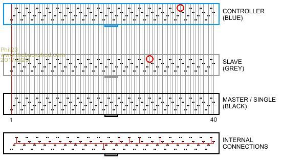 Cheers Phil |
||||
| Phil23 Guru Joined: 27/03/2016 Location: AustraliaPosts: 1667 |
Beat me to it Jim! |
||||
| Intellecta Newbie Joined: 07/05/2016 Location: AustraliaPosts: 22 |
Dear Peter, Thanks for update on the gerbers. I extracted the zip file and imported a layer into Diptrace. The tracks and pads are still showing errors. Where are the latest files have the errors reduced. I was going to send the 64pin to seeed pcb to do a trial run. The board has a good number of through hole components so students get a balance of soldering tasks. Any info appreciated. Tony Pugatschew |
||||
| matherp Guru Joined: 11/12/2012 Location: United KingdomPosts: 11513 |
Tony There are no new files as I still think they are correct. Please look at the files with GC-Preview and let me know where you think there is an error -post a picture. I've compared the files with the first set of boards which work fine and can't see a difference (the change was just a silkscreen difference) |
||||
| panky Guru Joined: 02/10/2012 Location: AustraliaPosts: 1127 |
Peter, Received your MZ Extreme Backpack100-4.3v1.0 PCB (the black instrumentation one with both GPS and accelerometer) from WW today. The schematic for this PCB on the first page of this post does not appear to equate to the board shown as I can not see any pinout info or reference to the GPS module. Can you confirm that the schematic is correct please or if not, post an updated one? Also, do you have a BOM for this board (even a rough list with part numbers would be helpfull) or any other documentation relating to this board? Thanks again for the great contributions you have made to the uMite world. Cheers, Doug. ... almost all of the Maximites, the MicromMites, the MM Extremes, the ArmMites, the PicoMite and loving it! |
||||
| WhiteWizzard Guru Joined: 05/04/2013 Location: United KingdomPosts: 2991 |
@Doug, I think it best I let Peter M send it as I don't want to send an out-of-date version (assuming I have one). During the MMX development, there were many emails exchanged on a daily basis between Peter, Geoff and myself. From all these emails, I have many with attachments and I do not want to confuse you by sending an incorrect schematic. I am out today; however IF I do come across what I think is the correct one when I get back home then I will send it through!  By the way - you need to add MZ100 onto your ever-growing 'footer': DonT SM1, Duinomite,CGCMM1, CGCMM2, 2xDimitech, 3xWW uMites, Micks MuP, Grogster 1A, 4xPeterM uM+, Zonker DIP-600, 3xCGuKits, CGuBoard2,SnadPic100,SilChip BP64 & Exp100,PM MMX144 .. and loving it! |
||||
| matherp Guru Joined: 11/12/2012 Location: United KingdomPosts: 11513 |
The GPS connection is marked H5 on the schematic You must use a DIP oscillator as there is a wiring error on the first release of the PCB relating to the SMD oscillator footprint. The DIP oscillators are 5V, note the 270R/470R voltage divider on the output of the oscillator to drop the output for the PIC. Non-standard parts SD card 114-00841-68 Regulator LD1085D2M33R L1 ELJNAR10MF Reset switch FSMRA4JH SMD USB 10118192-0001LF |
||||
| panky Guru Joined: 02/10/2012 Location: AustraliaPosts: 1127 |
Thanks Peter- will let you know how it goes together☺☺ @WW - see the new list below☺☺ ... almost all of the Maximites, the MicromMites, the MM Extremes, the ArmMites, the PicoMite and loving it! |
||||
| matherp Guru Joined: 11/12/2012 Location: United KingdomPosts: 11513 |
The originally posted 64-pin gerbers were corrupt - I believe these are now correct 2017-08-11_141014_backpack64MZ.zip I think the corruption only related to the 64-pin circuit but please check any other gerbers carefully before having any PCBs fabricated |
||||
| WhiteWizzard Guru Joined: 05/04/2013 Location: United KingdomPosts: 2991 |
So can I interest you in a PMMZ64 for your 'collection'! |
||||
| Boppa Guru Joined: 08/11/2016 Location: AustraliaPosts: 816 |
harking back to the 80 wire data cables - They were used with high speed data harddrives, and (so the story went) had a ground wire connected between every data wire (ie every data wire had a ground wire on either side) they were supposedly interchangeable with standard 40wire IDE cables, just had less chance of data corruption due to crosstalk between data lines.... |
||||
bigmik Guru Joined: 20/06/2011 Location: AustraliaPosts: 2981 |
Hi Bob, all, I often wondered about them, How did they get the GNDs to those wires when there was still only 40 pins on the sockets on the end of the cables? I might pull one apart and see if it is a special connector or just a `con job' Regards, Mick Mick's uMite Stuff can be found >>> HERE (Kindly hosted by Dontronics) <<< |
||||
| TassyJim Guru Joined: 07/08/2011 Location: AustraliaPosts: 6538 |
It's a bit too involved for use to make use of it as a 40 way cable. All the 'gnd' pins are interconnected along with the isolation wires.  Jim VK7JH MMedit |
||||
| panky Guru Joined: 02/10/2012 Location: AustraliaPosts: 1127 |
Phil, Can't see any details of Peter's MZ boards on your site - do you have populated and unpopulated price for the MZ64 board (the backpack one)? Doug ... almost all of the Maximites, the MicromMites, the MM Extremes, the ArmMites, the PicoMite and loving it! |
||||
| matherp Guru Joined: 11/12/2012 Location: United KingdomPosts: 11513 |
I was asked to confirm gerbers for the 144-pin PCB were OK so I'm posting an update just to be sure 2018-02-28_200529_Backpack144.zip Other MMX layouts are posted here |
||||
| matherp Guru Joined: 11/12/2012 Location: United KingdomPosts: 11513 |
Graeme (OA47) has just had some boards made up to the MX144 V1.2 gerbers in the previous post and kindly sent me one. I moved the parts across from my original prototype and have fully tested the new layout. I'm happy to report that the V1.2 gerbers have no known errors in either the wiring or the silkscreening. Note in the picture R37 and R38 are not installed. When using the through-hole 5V oscillator these make a potential divider on the output to reduce the signal to 3.3V for the PIC . I'm using the optional SMD 3.3V oscillator so these are not needed. Links USBVBUS and USBID are made enabling a USB keyboard to be connected (Top right) 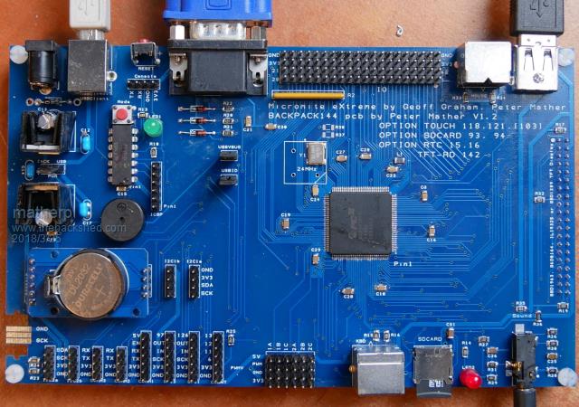 |
||||
enzo1965 Newbie Joined: 30/08/2018 Location: ItalyPosts: 2 |
Hi, for the Micromite eXtreme 144 I noticed that the 5 volts oscillator have a 24 MHz frequenzy, whereas the 3.3 volts have a 16 MHz frequenzy. I wanted to ask if the firmware is the same. Have a link for schematics and bom for Micromite eXtreme 144, and the latest firmware for this board? Thanks, best regards. |
||||
| matherp Guru Joined: 11/12/2012 Location: United KingdomPosts: 11513 |
Oscillator is 24MHz in both cases - I needed a footprint for the SMD version and it happened to be a 16MHz version should be SG8002CAPCB24MHZ or equivalent. No BOM other than schematic non-standard parts are: Audio socket - 35RASMT4BHNTRX SDcard socket - 114-00841-68 L1 ELJNAR10MF Reset switch FSMRA4JH SMD USB 10118192-0001LF Latest software here Schematic below: 2018-08-30_203741_schematic.pdf |
||||
| The Back Shed's forum code is written, and hosted, in Australia. | © JAQ Software 2026 |
