
|
|
Forum Index : Electronics : 6Kw Ozinverter build
| Author | Message | ||||
renewableMark Guru Joined: 09/12/2017 Location: AustraliaPosts: 1679 |
It's very hard to see in the photos, but the more levering I did the more the wires flattened out and made it worse, so just got to that point and thought as long as the ends are flat and a super big washer gets mounted flat and square then that will do. It will still fit a bolt with some conduit. Reckon if the wire got twisted a lot tighter it would have held it's shape better, the way mine was it just seem to flatten out too easy, I reckon that's where I went wrong. Cheers Caveman Mark Off grid eastern Melb |
||||
| renewableMark Guru Joined: 09/12/2017 Location: AustraliaPosts: 1679 |
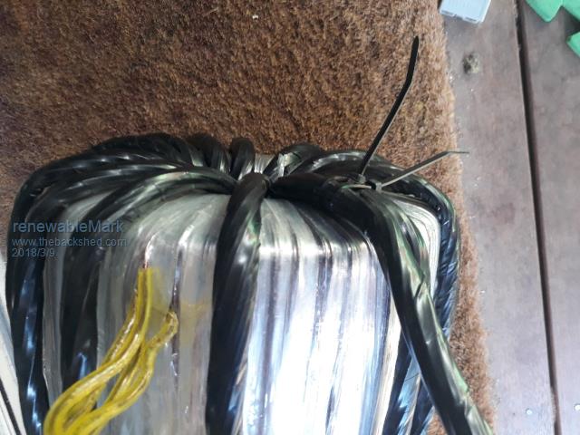 The mounting washer should fit on just fine. Cheers Caveman Mark Off grid eastern Melb |
||||
| Warpspeed Guru Joined: 09/08/2007 Location: AustraliaPosts: 4406 |
Yup ! Time for another beer. Cheers, ĀTony. |
||||
| Tinker Guru Joined: 07/11/2007 Location: AustraliaPosts: 1904 |
Looking at Marks fine effort I had an idea that somebody who has not yet wound the primary on could try out; Multi strand power cables seem to have an inner layer of an odd number of wires wrapped around a central wire. This then has another layer of wires wrapped around but in the opposite direction. I suppose this is to keep the lot firm and round when bending around corners. So, my idea: Make a plywood disk with a central hole of the individual wire (strand) diameter. Around this, spaced away a little for rigidity, a circle of the number of holes that would fit tightly next to one another around the center strand. (number depends on wire diameter). Procedure: feed center strand through center hole and outer strands to each hole, then tie up to a firm post. The rest of the wires are stretched out in a straight line from the other side of this plywood disk. Then walk backwards while rotating the disk, this should neatly wrap all the outer wires around the center one. When the inner core is complete make another plywood disk with this core's central hole size and the required outer strand hole ring. Repeat the above but rotating the disk the opposite way. Now, I have not tried this yet, it should work theoretically. As there is plenty of left over 1.8mm wire around here I might give it a go for a short cable just for fun and to prove a point. Klaus |
||||
| renewableMark Guru Joined: 09/12/2017 Location: AustraliaPosts: 1679 |
I'm thinking Klaus that would be a complicated operation even with a very expensive machine, trying that at home seems overly tedious. Good luck mate. Reckon I'll fork out for welding cable on the next one. Cheers Caveman Mark Off grid eastern Melb |
||||
| Tinker Guru Joined: 07/11/2007 Location: AustraliaPosts: 1904 |
Mark, you can do better than welding cable! Look at this picture of my double stack toroid and notice the center hole size. That's a total of 90 mm sq BTW for the primary, something you will *never* manage with round cable. 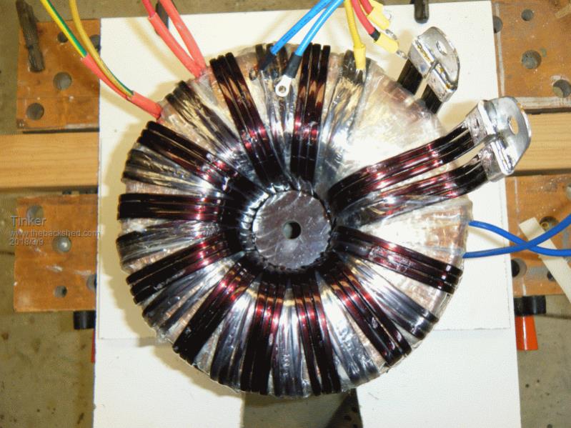 That square wire (3x5mm) I got for scrap price as a leftover of an order from a local firm that makes this kind of wire to any size you want - if you order 200kg. For leftovers you take whatever they have at the time. Apparently there are two companies in Australia making this, one here in Perth and the other in the eastern states somewhere - maybe near you. I found out about them from a local motor re-winder. Klaus |
||||
| Warpspeed Guru Joined: 09/08/2007 Location: AustraliaPosts: 4406 |
Circles have magical mathematical properties. If you take one central wire (as pointed out above by Klaus) six more wires will fit very neatly around the central wire. Making a seven stranded cable. Now if you place more wires around that, you will find that the next layer will have six more wires than the previous layer. So we have 1 + 6 + 12 making a nineteen stranded cable. Another added layer will again amazingly have six more wires than the layer underneath. So the next size up will be 1 + 6 + 12 + 18 making a thirty seven stranded cable. And it just keeps on going..... But it also works the other way too. If you are winding layers on a toroid, each layer will theoretically have space only for six less turns than the previous layer. It never quite works out exactly, because its very hard to fit turns tightly together when hand winding, and if you add insulation between layers that upsets things too. But as a rough rule of thumb when toroid winding, you might assume that if you can just fit for example 160 turns on the first layer, you might be lucky to fit 154 on the next layer, and 148 on a third layer. So to be safe you might decide to make all three layers say 145 or 146 turns. The first layer will have a big gap, the next layer about half that gap, and a third layer will just about have no gap, in this example. Of course in practice there should be no huge gap, you spread the turns of the first layers. So you mark out the circumference (in this example) into maybe 146 divisions and work to that... If you know the wire diameter and the toroid hole size, and number of layers, you can come pretty close to anticipating what will fit. Rectangular wire is especially nice to work with, it bends much more readily than round wire for the same copper area, and its much more space efficient. Any large transformer winding business will probably have some in stock. Cheers, ĀTony. |
||||
| renewableMark Guru Joined: 09/12/2017 Location: AustraliaPosts: 1679 |
Hey fellas, if you wanted to do a primary of 70mm, could you just wind one layer of 35mm and then a second one of 35 and join the ends of each together? Should be the same yeah? And probably a lot neater. On another matter I got the changeover switch fitted. Spoke to battery fellas today and will order that. 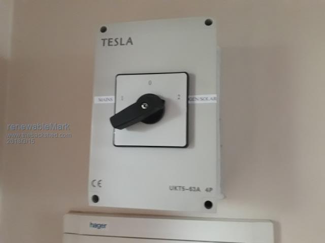 Cheers Caveman Mark Off grid eastern Melb |
||||
| Warpspeed Guru Joined: 09/08/2007 Location: AustraliaPosts: 4406 |
Yes definitely. Its a just case of what will fit best into the available space, as well as what the standard available cable sizes are, and what you may already have there to use. If its plastic insulated, the thinner cable can actually take up more total space, but may fit more readily and be easier to wind. Cheers, ĀTony. |
||||
| renewableMark Guru Joined: 09/12/2017 Location: AustraliaPosts: 1679 |
Thanks Tony. I need to get more solar cable too, found this place is a bit cheaper than my last supplier. Better comply to the code and get the correct signs too here Need to get 1M of welding wire for the choke, battery cable for the power board, then I'm just about ready to test the sucker! Cheers Caveman Mark Off grid eastern Melb |
||||
| renewableMark Guru Joined: 09/12/2017 Location: AustraliaPosts: 1679 |
Finally got around to cutting the heatsinks, jeez that made a mess! Tiny al filings all over the courtyard, I reckon there was that much aluminium flying around the airport picked me up as a low flying plane! Tinker, not wrong about full mask, ended up using my welding helmet and full overalls. Have to drill the heatsinks now then ready for testing. So them you hook the power board up to the control board via ribbon cable without caps and look for this (courtesy of Mad) The pins marked 5 & 6 will both have squarewave signals and 7 & 8 will have the fuzzy SPWM signal. 5,6,7 & 8 are the signals coming from the EG8010, so if you have these signals the EG8010 chip is working but it will be shutting down after 3 seconds as it is not detecting any voltage feedback. If you just have the power board powered up on its own you will get a square wave on the IR2110 on the pin marked 1 in the diagram below, 2 will have a very weak barely visible output, 3 will have a fuzzy wave that is the SPWM(sinewave pulse width modulation) pin 4 will also have a barely visible signal. If there is no out put at all from the IR2110 check that the 13V power supply is working. " One thing Warp suggested was to fit only 4 fets, then add another 4 each time and check for any significant difference, maybe to a total of 16 mosfets initially. Then add the toroid and voltage feedback connections and test for sinewave on 240 output of toroid. If all is well then add the caps and test again. So is that sequence correct? Now if I am to try and add the rest of the fets at which stage would I add them? I'm thinking before the caps get fitted yeah? Cheers Caveman Mark Off grid eastern Melb |
||||
| renewableMark Guru Joined: 09/12/2017 Location: AustraliaPosts: 1679 |
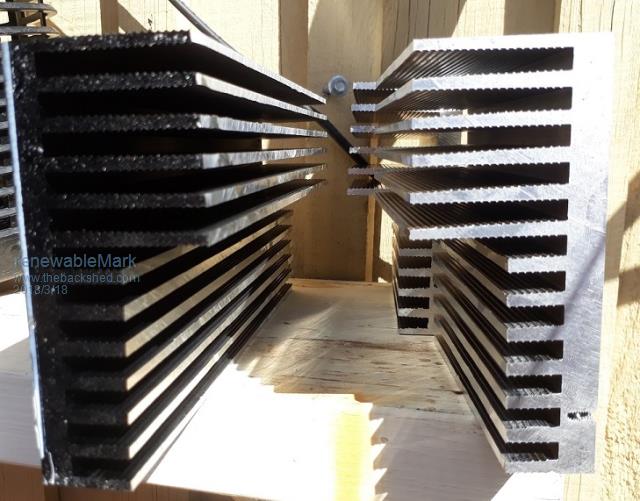 You do get a very nice finish with the correct blade. Cheers Caveman Mark Off grid eastern Melb |
||||
| Warpspeed Guru Joined: 09/08/2007 Location: AustraliaPosts: 4406 |
Should have warned you about the blizzard of ally chips. The noise can be quite memorable as well. I do that sort of thing way out in the middle of the lawn these days. I think you said you used a Bunnings blade ? what was it exactly, it seems to leave a very nice cut. (How is your solar controller going). Cheers, ĀTony. |
||||
Madness Guru Joined: 08/10/2011 Location: AustraliaPosts: 2498 |
Mark nothing wrong with starting with 4 FETs you can do an initial check with no toriod. Just leave the big caps off and run through a resistor, the 2 you used in parallel to test RDS on work fine. You should get a good sinewave out with no load, it may be slightly in a triangle shape, that is okay. While running through the resistor you can't put more than maybe 50 W load on it. Once you have a sinewave you could try bypassing the resistor and run a 1200W load for a quick test. The sinewave will be more triangular due to no caps. Once you have confirmed the first 4 are good then start adding more MOSFETs. It is a bit time consuming but best to be patient. Keep an eye on the DC current, should be 50W or less with no load, any more and you need to find out why. Those heatsinks look like you bought them. I have used blades made for timber as well but the proper Aluminium ones are much better. There are only 10 types of people in the world: those who understand binary, and those who don't. |
||||
| renewableMark Guru Joined: 09/12/2017 Location: AustraliaPosts: 1679 |
Thanks fellas, it was an aluminium Irwin blade 254mm?, used the Lanox, boy does that make a difference big time! Warp, check your inbox regarding the solar controller, check it's not full too, may have to delete some. Give me a yell if you ever want to borrow the table saw, it's only a small one and fits in the back tray easy as. Jeez those crimpers you lent me are bloody good, beats struggling with vice grips and a hammer. Thanks for the instructions Mad. I got the cutouts for the cases done today, had to do the noisy bits while the wife was out, I'm not allowed to do that kind of stuff while she is around. Also fellas where have you been connecting earth points? Cheers Caveman Mark Off grid eastern Melb |
||||
| Warpspeed Guru Joined: 09/08/2007 Location: AustraliaPosts: 4406 |
Thanks Mark my in box was 100% full, so did not receive your latest. Cheers, ĀTony. |
||||
| Madness Guru Joined: 08/10/2011 Location: AustraliaPosts: 2498 |
The case will be your earth which also connects to the pads on the power PCB with the safety caps connected to them. I don't bother with earthing it until final assembly. In your switchboard for the house Neutral will be bonded to earth AFIK that is the only place it should be. Buy your wife some ear plugs and tell her to shut the full cup up. If you get those Aluminium chips and grind them to a fine powder and mix with rust you have Thermite, that will give your wife something to whinge about. There are only 10 types of people in the world: those who understand binary, and those who don't. |
||||
| Warpspeed Guru Joined: 09/08/2007 Location: AustraliaPosts: 4406 |
Yes only place neutral can be linked to earth is at the main power board (its a safety issue). Reason being, that if the neutral goes open circuit, return current will then flow through the earth connection, and you would not be aware that there was a problem. If the earth connection then fails open circuit, the "equipment" can then become alive at full mains voltage. Very nasty... Cheers, ĀTony. |
||||
| renewableMark Guru Joined: 09/12/2017 Location: AustraliaPosts: 1679 |
So with the output of the toroid, which one is neutral and live? Either or? Cheers Caveman Mark Off grid eastern Melb |
||||
| Warpspeed Guru Joined: 09/08/2007 Location: AustraliaPosts: 4406 |
It does not matter, because the secondary is a completely floating winding. Cheers, ĀTony. |
||||
| The Back Shed's forum code is written, and hosted, in Australia. | © JAQ Software 2026 |
